EP1265188B1 - Pattern extraction apparatus and method - Google Patents
Pattern extraction apparatus and method Download PDFInfo
- Publication number
- EP1265188B1 EP1265188B1 EP02019040A EP02019040A EP1265188B1 EP 1265188 B1 EP1265188 B1 EP 1265188B1 EP 02019040 A EP02019040 A EP 02019040A EP 02019040 A EP02019040 A EP 02019040A EP 1265188 B1 EP1265188 B1 EP 1265188B1
- Authority
- EP
- European Patent Office
- Prior art keywords
- enclosing
- rectangle
- character
- rectangles
- characters
- Prior art date
- Legal status (The legal status is an assumption and is not a legal conclusion. Google has not performed a legal analysis and makes no representation as to the accuracy of the status listed.)
- Expired - Lifetime
Links
Images


Classifications
-
- G—PHYSICS
- G06—COMPUTING; CALCULATING OR COUNTING
- G06V—IMAGE OR VIDEO RECOGNITION OR UNDERSTANDING
- G06V30/00—Character recognition; Recognising digital ink; Document-oriented image-based pattern recognition
- G06V30/40—Document-oriented image-based pattern recognition
- G06V30/41—Analysis of document content
- G06V30/414—Extracting the geometrical structure, e.g. layout tree; Block segmentation, e.g. bounding boxes for graphics or text
-
- G—PHYSICS
- G06—COMPUTING; CALCULATING OR COUNTING
- G06V—IMAGE OR VIDEO RECOGNITION OR UNDERSTANDING
- G06V10/00—Arrangements for image or video recognition or understanding
- G06V10/10—Image acquisition
-
- G—PHYSICS
- G06—COMPUTING; CALCULATING OR COUNTING
- G06V—IMAGE OR VIDEO RECOGNITION OR UNDERSTANDING
- G06V30/00—Character recognition; Recognising digital ink; Document-oriented image-based pattern recognition
- G06V30/40—Document-oriented image-based pattern recognition
- G06V30/41—Analysis of document content
- G06V30/416—Extracting the logical structure, e.g. chapters, sections or page numbers; Identifying elements of the document, e.g. authors
Definitions
- the present invention relates to image recognizing technology for reading documents, drawings, etc., and more specifically to pattern extraction technology for extracting a pattern and in particular a character string such as a headline from an image.
- JP-A- 4-287168 which discloses a method of automatically extracting a keyword from a file
- the descriptions of a drawing, a photograph, and a table are positioned at the top or foot of each of them to be described.
- the descriptions can be extracted as a character string or a character string area, and the characters forming the descriptions are recognized and entered as a keyword.
- JP-A- 8-293003 which discloses a character string extracting method and a character string extraction apparatus based on the method, a character string recognizing apparatus and a character string recognizing system
- JP-A- 8-293003 which discloses a character string extracting method and a character string extraction apparatus based on the method, a character string recognizing apparatus and a character string recognizing system
- all characters in the image are extracted, continuous characters are grouped as a character string, the feature amount of each group is compared with an entered feature amount model, discriminated, and extracted as a character string.
- Continuous characters refers to a character string
- a feature amount refers to a type and size of a character such as a kanji (Chinese character), a numerical character, etc.
- an input image contains vertically arranged characters or horizontally arranged characters. Then, a labelling process is performed on the input image and its black/white inverse image to obtain connected elements having a series of picture elements in the same color.
- a character candidate is found based on the size, thickness, and relative position of each connected element.
- the character candidate obtained from the connected element of an input image is referred to as a black character candidate, and the character candidate obtained from the connected element of an inverse image is referred to as a white character candidate.
- the color of characters is determined from the number of black character candidates and white character candidates. When the character color is black, only the connected elements of an input image are to be processed in the subsequent steps. When the character color is white, only the connected elements of the black/white inverse image are to be processed thereafter.
- a character string area is obtained after merging the connected elements to be processed.
- the connected element which is contained in the character string area and is equal to or larger than a threshold in thickness is extracted as a character element.
- the threshold is a value indicating a constant ratio to the maximum value in thickness of a connected element.
- the connected element extracted as a character element is generated as an image, and is defined as a character string in a character recognizing process.
- the entire image is labelled, and an overlapping nest integrating process is performed on the obtained black picture element connection areas. Then, the character size of the text of the entire document is determined from the obtained black picture element connection area. Based on the value, the attribute of each connection area is determined. When it is determined that the attribute of a rectangle is a character, vertical or horizontal integration is repeated on the rectangle, thereby defining a character string.
- the character color is determined during the character extracting process, and the character line width is fixed to a standard value. Furthermore, a character string area is set in line units (or in column units). Therefore, it has been a problem that it is quite difficult to extract a character string from a complicated image comprising a background pattern containing a combination of white and black portions, various types of fonts, a color document, a plurality of lines, a combination of vertical and horizontal character strings, and a compound of them.
- the relationship between black character candidates and white character candidate in number is not a reliable criterion for determining a character color.
- the determination is irrevocable if it is mistakenly made, thereby failing in the final character recognition.
- the entire document can be integrated in the overlapping nest integrating process.
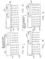
- FIG. 1 shows an example of integrating the entire document in the proposed overlapping nest integrating process.
- FIG. 1A it is assumed that the enclosing rectangles K61 through K65 of the connected elements have been obtained from an input image.
- the enclosing rectangle K61 and the enclosing rectangle K62 are integrated because they overlap each other.
- an enclosing rectangle K66 enclosing the enclosing rectangle K61 and the enclosing rectangle K62 is generated.
- the enclosing rectangle K66 overlaps the enclosing rectangle K63.
- the enclosing rectangle K67 encompassing the enclosing rectangle K66 and the enclosing rectangle K63 is generated as shown in FIG. 1C.
- the enclosing rectangle K67 overlaps the enclosing rectangle K64. Therefore, they are integrated.
- all enclosing rectangles K61 through K65 shown in FIG. 1A are integrated, and the enclosing rectangle K68 encompassing the enclosing rectangles K61 through K65 is generated as shown in FIG. 1D.
- US-A-5 757 957 discloses a pattern extraction apparatus and method according to the preamble of each of the corresponding independent claims.
- the apparatus/method generates a histogram of frequency of occurrence of rectangle as a function of rectangle-height, and a value t is defined as a value proportional to the total number of rectangles. The largest rectangle height among those of which the occurrence frequencies exceed t is taken as the reference character size.
- An embodiment of the present invention relating to the technology of recognizing an image by reading a document, drawings, etc., may provide a pattern extraction apparatus for extracting a character string from a complicated image, and recognizing even a thin character line and recognizing a character without mis-recognizing a character color.
- a pattern extraction apparatus comprising:
- a pattern extraction method comprising the steps of:
- a computer-readable storage medium storing a program causing a computer to execute a pattern extraction method comprising:
- a character string can be extracted with precision from a complicated image comprising a background pattern containing a combination of white and black portions, various types of fonts, a color document, a plurality of lines, a combination of vertical and horizontal character strings, and a compound of them.
- the enclosing rectangle formed by a part of one character is smaller than an enclosing rectangle formed for an entire character.
- the evaluation of the frequency of the enclosing rectangle formed by a part of one character can be set lower, and the influence of the size of a part of a character can be reduced in estimating the size of a character. Therefore, the character size can be estimated with high precision even when the overlapping nest integrating process is not performed.
- the apparatus of the present invention is applied to an input image including headline characters to be extracted and text characters, whereby the enclosing rectangles include at least one headline character box and at least one text character box, the apparatus further comprising: grouping means for selecting, from the enclosing rectangles, candidates for headline character boxes; counting means for counting, in each of the enclosing rectangles which are candidates for headline character boxes, the number of smaller enclosing rectangles of the size of text characters contained in the enclosing rectangle; and removing means for removing, from the candidates for headline character boxes, any enclosing rectangle containing a predetermined number or more of the smaller enclosing rectangles.
- each enclosing rectangle has a position defined by co-ordinates in x and y co-ordinate axes of the input image
- the apparatus further comprises: projecting means for assigning a rectangle number identifying each of the enclosed rectangles, and projecting each of the rectangle numbers onto said x and y co-ordinate axes to form a projection table for candidates for a text character box in which each rectangle number is stored at the co-ordinates of the corresponding enclosing rectangle.
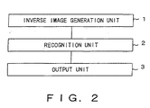
- FIG. 2 is a block diagram showing the configuration of a pattern extraction apparatus useful for understanding the present invention.
- an inverse image generation unit 1 generates an inverse image obtained by changing the label of an input image.
- a recognition unit 2 performs a pattern recognizing process on a pattern extracted from the inverse image generated by the inverse image generation unit 1.
- An output unit 3 outputs a nonoverlapping combination of an area of a pattern extracted from the input image and an area of a pattern extracted from the inverse image generated by the inverse image generation unit 1 as a consistent combination from among the recognition results from the recognition unit 2.
- the recognizing process can be performed on both characters formed by black picture elements and white characters against the black background.
- the recognition results of the characters of black picture elements can be output in combination with the recognition results of the white characters against the black background.
- the color of a character is determined by the number of black character candidates and white character candidates. Therefore, when it is determined that the character color is black, only the connected elements of the input image is to be processed thereafter and a black character can be correctly recognized, but a white character against the black background cannot be recognized. Similarly, when it is determined that the character color is white, only the connected elements of the black/white inverse image is to be processed for character recognition and a white character against the black background can be correctly recognized, but a black character cannot be recognized.
- the FIG, 2 apparatus the above described mis-recognition can be avoided.
- a character string can be extracted with precision from a complicated image comprising a background pattern containing a combination of white and black portions, various types of fonts, a color document, a plurality of lines, a combination of vertical and horizontal character strings, and a compound of them.
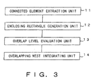
- FIG. 3 is a block diagram showing the configuration of another pattern extraction apparatus useful for understanding the present invention.
- a connected element extraction unit 11 extracts connected elements of an input image.
- An enclosing rectangle generation unit 12 generates an enclosing rectangle of connected elements extracted by the connected element extraction unit 11.
- An overlap level evaluation unit 13 computes the number of enclosing rectangles overlapping the enclosing rectangle generated by the enclosing rectangle generation unit 12.
- An overlapping nest integrating unit 14 performs the overlapping nest integrating process based on the computation result of the overlap level evaluation unit 13.
- the overlapping nest integrating process can be partially performed. That is, the process can be performed only on an enclosing rectangle having a high overlap level, and can be suppressed on an enclosing rectangle having a low overlap level. As a result, the enclosing rectangle of headline characters can be prevented from being lost by enclosing rectangles being integrated on the entire screen.
- a part of a drawing or a photograph having a high overlap level can be absorbed or integrated into a larger rectangle.
- an enclosing rectangle of a part of a drawing or a photograph remains as is to be mistakenly extracted as headline characters or mistakenly integrated into a rectangle as headline characters.
- headline characters can be extracted with high precision even if the headline characters coexist with a drawing, a photograph, etc.
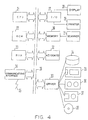
- FIG. 4 is a block diagram showing the system configuration of the character string extraction apparatus of FIG. 2 or FIG. 3, which is also applicable to the present invention.
- 21 is a central processing unit (CPU) for performing an entire process.
- 22 is read-only memory (ROM).
- 23 is random-access memory (RAM).
- 24 is a communications interface.
- 25 is a communications network.
- 26 is a bus.
- 27 is an input/output interface.
- 28 is a display for displaying, for example, recognition results of headline characters, etc.
- 29 is a printer for printing, for example, recognition results of headline characters, etc.
- 30 is memory for temporarily storing data read by a scanner 31.
- 31 is a scanner for reading an input image, etc.
- 32 is a keyboard.
- 33 is a driver for driving a storage medium.
- 34 is a hard disk.
- 35 is an IC memory card.
- 36 is a magnetic tape.
- a program for performing a pattern extracting process is stored in a storage medium such as the hard disk 34, IC memory card 35, magnetic tape 36, floppy disk 37, optical disk 38, etc.
- Headline characters, etc. can be extracted from a document image of, for example, newspapers, magazines, etc. by reading a program, etc. for performing a pattern extracting process from the storage media to the RAM 23.
- a program, etc. for performing a pattern extracting process can be stored in the ROM 22.
- a program, etc. for performing a pattern extracting process can be retrieved from the communications network 25 through the communications interface 24.
- a LAN local area network
- a WAN wide area network
- the Internet an analog telephone network
- ISDN integral service digital network
- a wireless communications network such as a PHS (personal handy system), satellite communications, etc.
- the CPU 21 labels an input image read by the scanner 31, and generates an enclosing rectangle for connected elements assigned the same labels. Then, it checks the overlap level of each enclosing rectangle, and performs the overlapping nest integrating process on the enclosing rectangles overlapping each other at a high overlap level. Next, it groups the enclosing rectangles treated in the overlapping nest integrating process, extracts headline characters from among the grouping results, and outputs the extraction result on the display 28 or the printer 29.
- FIG. 5 shows the operation of a character extraction apparatus useful for understanding the present invention.
- FIG. 5A it is assumed that characters of black picture elements arranged in two lines enclosed by a black character box, and white characters , vertically arranged against the black background have been input as an input image, and that the character string and the character string are extracted from the input image.
- connected elements containing a series of picture elements of the same color are extracted from the input image based on the color of picture elements.
- the connected elements are extracted for each color. Since the input image shown in FIG. 5A is a black-and-white binary image, the connected elements containing black picture elements and white picture elements are extracted also from the black/white inverse image. The inverse image is obtained by exchanging the colors between the background of the input image and the characters as shown in FIG. 5A.
- a different label is assigned to each group of connected elements of black picture elements in the input image, and a different label is assigned to each group of connected elements of black picture elements in the black/white inverse image.
- connected elements probably containing common character strings or character string groups based on the relative positions and the similarity in thickness among connected elements are grouped.
- the similarity of connected elements in thickness refers to the ratio of the number of boundary picture elements to the total number of picture elements of connected elements.
- Common character strings or character string groups refer to a set of character strings representing the same meanings .
- the character box enclosing the input image, that is, the characters is connected by the black picture elements to the black picture element area corresponding to the background against the white characters . Therefore, they are grouped as a group b.
- the black picture element area corresponding to the background against the white characters as an inverse image is connected by the black picture elements to the character box enclosing the characters , they are grouped as a group a1. Since the characters as an inverse image are close to each other and the same in thickness, the characters , , and are grouped as a group b1.
- the group a is formed by relatively small characters against a white background area
- the group b is formed by relatively large white characters against a black background area.
- the group b is not recognized as white characters against the black background. It is only recognized that the group a contains characters against a white background, and that the group b is blackish as a whole. Therefore, the characters cannot be recognized even if a character recognizing process is performed on the background area formed by the black picture elements of the group b.
- the group a1 is formed by relatively small white characters against a black background area
- the group b1 is formed by relatively large characters against a white background area.
- the group b1 is not recognized as white characters against the black background. It is only recognized that the group a1 is blackish as a whole, and that the group b1 contains characters against the white background. Therefore, the characters cannot be recognized even if a character recognizing process is performed on the background area formed by the black picture elements of the group a1.
- the character recognizing process is performed on each group.
- a sum of the inverse numbers of the distance values of the first character candidates of the characters obtained as the recognition results is defined as the character recognition level of the group. Therefore, if the character recognition level of a group is high, there is a strong possibility that the group is a character string to be extracted.
- the evaluation value of a group is obtained by weighting the character recognition level of a group by the area of the rectangular area enclosing the group.
- the evaluation value is obtained for the combinations of all groups to define the evaluation value of a combination.
- groups are combined, only the groups whose rectangular areas enclosing the groups are not overlapping each other are associated, and all combinations of the groups whose rectangular areas enclosing the groups are not overlapping each other are obtained.
- FIG. 5B shows the combination of groups whose rectangular areas enclosing the groups are not overlapping each other.
- the combinations of the groups a and b, a and a1, b and a1, b and b1, and a1 and b1 are removed from all combinations.
- the combinations to be removed are indicated by the broken lines in FIG. 5B.
- the evaluation values are computed for all combinations of groups connected by solid lines. As a result, the combination of the group having the highest evaluation value is extracted as a character string.
- FIG. 5C shows a computation result
- the combination of groups a and b is selected. After the character recognizing process is performed on the pattern extracted from the group a, the character string is output. After the character recognizing process is performed on the pattern extracted from the group b1, the character string is output.
- the character recognizing process is performed on the group b, then the character string cannot be correctly recognized because the group b is formed by the character box enclosing the characters which is an input image, and the black picture element area corresponding to the background against the white characters .
- the recognizing process is performed using only the pattern extracted from the input image shown in FIG. 5A, then the character string can be extracted, but the character string cannot be extracted.
- the character recognizing process is performed on the group a1, then the character string cannot be correctly recognized because the group a1 is formed by the black picture element area corresponding to the background against the white characters , which is an inverse image, and the character box enclosing the characters .
- the recognizing process is performed using only the pattern extracted from the inverse image shown in FIG. 5A, then the character string can be extracted, but the character string cannot be extracted.
- the character recognizing process is performed using both the pattern extracted from the input image and the pattern extracted from the inverse image.
- the character string is extracted from the input image while the character string is extracted from the inverse image. Therefore, both the character strings and can be correctly extracted.
- FIG. 6 is a block diagram showing the configuration of the character extraction apparatus for implementing the above operation.
- a character string extraction apparatus 41 comprises a connected element extraction unit 42, a grouping unit 43, a character recognition unit 44, a combination evaluation unit 45, and a character string extraction unit 46.
- the connected element extraction unit 42 extracts connected elements containing a series of picture elements of the same color based on the color of the picture elements in the input image. If the input image is a color image, then connected elements are extracted for each color. If the input image is a monochrome binary image, then black and white picture elements of the connected elements in an inverse image are also extracted for each color.
- the grouping unit 43 groups connected elements which possibly have common character strings or character string groups based on the relative positions between the connected elements and the similarity in thickness of connected elements.
- the character recognition unit 44 performs the character recognizing process for each group and obtains the character recognition level of a group.
- the combination evaluation unit 45 obtains an evaluation value of a group, and then obtains an evaluation value of a combination.
- the character string extraction unit 46 extracts as a character string a combination of groups having the highest evaluation value of a combination.
- the character string extraction apparatus 41 shown in FIG. 6 groups connected elements based on the similarity, performs the character recognizing process for each group, assigns a character string level to each group, and extracts a combination of consistent groups. Therefore, a character string can be extracted from a complicated image such as a background pattern containing black and white picture elements, a color document, etc.
- the character string extraction apparatus 41 shown in FIG. 6 and the storage medium do not determine a color during the extracting process, do not assume a character string area, or do not determine the line width of a standard character in the extracting process, thereby improving the precision in extraction of character string.
- the character string extraction apparatus 41 of FIG. 6 is described in detail by referring to the attached drawings.
- a character string is extracted from a monochrome binary image such as a headline of newspapers, etc.
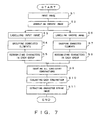
- FIG. 7 is a flowchart showing the operation of the character extraction apparatus.
- step S1 an image is input in step S1, and control is passed to step S2.
- step S2 a white/black inverse image is generated against the input image. Then, an input image process and an inverse image process are concurrently performed. When the input image process is performed, control is passed to step S3. When the inverse image process is performed, then control is passed to step S6.
- a labelling process is performed to obtain respective connected elements.
- a labelling process is performed on the input image.
- a labelling process is performed on the inverse image.
- the respective connected elements are grouped. As shown in FIG. 7, the connected elements of the input image are grouped in step S4, and the connected elements of the inverse image are grouped in step S7.
- the character recognizing process is performed on both groups.
- the character recognizing process is performed on the groups of the input image in step S5, and the character recognizing process is performed on the groups of the inverse image in step S8.
- step S9 groups having enclosing rectangular areas overlapping each other are removed from the combinations of groups, and the consistent combinations are all counted.
- each of the candidates for combinations is evaluated based on the evaluation value.
- the evaluation value of each group is a function between the character recognition level of each group and the area of the rectangular area enclosing each group.
- the evaluation value of a combination is obtained by combining the evaluation values of groups in a consistent combination.
- step S11 a character string corresponding to the group having the highest evaluation value is extracted, and the process terminates.
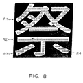
- FIG. 8 shows the labelling process referred to in FIG. 7.
- a white character against the black background contains four connected elements R1 through R4 respectively assigned the numbers 1 through 4.
- identifying connected elements formed by a series of picture elements of the same color (white picture elements in FIG. 4) by numbers, etc. as shown in FIG. 8 is referred to as 'labelling'.
- FIG. 9 is a flowchart showing the grouping process of FIG. 7.
- step S21 a candidate for a character element is selected in step S21.
- target connected elements are limited.
- connected elements whose enclosing rectangle is equal to or smaller than a standard size are removed to be set as those not to be processed in the subsequent process because they cannot be candidates for character elements. Then, control is passed to step S22.
- step S22 the vicinity of connected elements is set.
- the vicinity refers to an area formed by encompassing the enclosing rectangle of connected elements by a frame of an approximate size.
- a part of a connected element is in the vicinity of another connected element, it is referred to as a vicinal connected element.
- step S23 the connected element is linked to its vicinal connected element.
- Linking refers to associating a connected element with its vicinal connected element after determining whether the connected element and its vicinal connected element belong to the same character string or the same character string group.
- Connected elements are linked based on the relative position and similarity in thickness of the connected elements.
- the relative position and similarity in thickness of the connected elements are referred to as familial similarity of the connected elements.
- the familial similarity of all connected elements and all vicinal connected elements is determined in step S23, and control is passed to step S24.
- step S24 a connected element linked with its vicinal connected element is extracted as a group.
- connected elements are linked in various methods. For example, connected elements A, B, and C are linked, but the connected elements A and C may not be directly connected. Similarly, the connected element A is linked to the connected element B, but the connected element B may not be linked to the connected element A.
- step S24 a set of connected elements linked for arch connection is retrieved as a group.
- FIG. 10 shows an example of connected elements and their enclosing rectangle.
- the character is a connected element, and its enclosing rectangle is dx in length in the x direction and dy in the y direction.
- FIG. 11 is a flowchart showing the method of limiting the target connected elements.
- the threshold of the length dx in the x direction and the threshold of the length dy in the y direction of the enclosing rectangle of the connected elements are set to th1 and th2.
- the length dy in the x direction and the length dy in the y direction are input in step S31 shown in FIG. 11, it is determined in step S32 whether or not the length dy in the y direction is smaller than the threshold th2.
- step S32 control is passed to step S33 if the length dy in the y direction is smaller than the threshold th2, and control is passed to step S36 if the length dy in the y direction is not smaller than the threshold th2.
- step S33 control is passed to step S35 if the length dx in the x direction is larger than the threshold th1 and smaller than the threshold th2, and control is passed to step S34 if the length dx in the x direction is equal to or smaller than the threshold th1 or equal to or larger than the threshold th2.
- step S34 control is passed to step S35 if the length dy in the y direction is larger than the threshold th1, and control is passed to step S36 if it is not larger than the threshold th1.
- step S35 it is assumed in step S35 that the corresponding connected element can be defined as a candidate for a character element. It is assumed in step S36 that the corresponding connected element is not to be processed in the subsequent steps, thereby terminating the process.
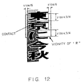
- FIG. 12 shows the vicinity of connected elements.
- the vicinity is an area formed when the circumference of the enclosing rectangle of connected elements is encompassed by a frame of an appropriate size.
- An appropriate size indicates, as shown in FIG. 12, the space of 1/6 of the width of the character on both sides, and the space of 3/4 of the height of the character above and below the character if the characters are vertically printed. Similarly, the vicinity can be defined for horizontally printed characters.
- the vicinity of the character includes a part of the character and the character . Therefore, it is determined that the vicinal connected elements of the character are the characters and .
- the half of the background area of shown in FIG. 12 contains large and small dots forming a net pattern. Since the character looks connected at the portion encompassed by the circle, the character is assumed to be a connected element.
- the character Assuming that the character is not connected at the portion encompassed by the circle in FIG. 12, the character comprises the top element and the other three connected elements. Relating to the vicinity of each of the connected elements, the connected elements are checked for each size.
- FIG. 13 shows the familial similarity of the connected elements.
- the familial similarity of the connected element depends on the relative positions between the connected elements and the difference in average thickness between the connected elements.
- the average thickness is represented by the ratio of the number of boundary picture elements to the total number of picture elements of the connected elements, that is, (number of boundary picture elements / total number of picture elements).
- the familial similarity of the vicinal connected element B to the connected element A shown in FIG. 13 is as high as the familial similarity of the connected element C to the connected element B. Therefore, it is determined that the connected elements A, B, and C belong to the same character string. In this example, the familial similarity of the connected element C to the connected element B is considered only in element of thickness.
- FIG. 14 shows the method of computing the character recognition level of a group.
- the character recognition level of a group is represented by a sum of the inverse numbers of the distance values of the first character candidates of the character recognition results after performing a character recognizing process for each group. If a character has a small distance value, it means that the character has a high recognition level.
- the net pattern by dots as the background area against the character string shown in FIG. 14 is not processed in the subsequent steps only if the pattern is formed by complete dots. If the network pattern is formed as connected dots, it is classified as a group B. It is predicted that both the group B and the group of an inverse image of the net pattern by dots have the character recognition level of 0. Since the net pattern of the group B overlaps the group A comprising the character string the group B is not output after being combined with the group A.
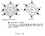
- FIG. 15 shows an association graph and a clique.
- the groups are associated if their rectangular areas do not overlap each other.
- the concept of an association graph and a clique is used to obtain all combinations of groups whose rectangular areas do not overlap each other.
- an association graph is generated to count consistent combinations, and all cliques, that is, complete graphs, are obtained so that the groups whose rectangular areas overlap each other can be removed from the combination of groups.
- the association graph shown in FIG. 15 is generated, with groups defined as nodes, by connecting via paths (solid lines) the nodes corresponding to the groups whose rectangular areas do not overlap each other.
- the nodes corresponding to the groups whose rectangular area overlap each other are not connected through paths.
- a clique refers to combinations of consistent nodes.
- a plurality of cliques are generated from the association graph, and each clique is a complete graph in which all nodes are connected through paths. All combinations of consistent groups can be obtained by obtaining cliques from the association graph.
- the evaluation value of a combination of consistent groups can be obtained.
- a net pattern as a background area, spots, etc. can be removed from the targets to be processed.
- an association graph comprising nodes N1 through N8 are generated as shown in FIG. 15, a complete graph is obtained such that paths are connected from each node to all other nodes.
- the node N1 is a node of the clique. Since the node N2 is not connected to the node N8, the node N2 is removed from the nodes of the clique. Since the node N3 is connected to all other nodes N1, N2, and N4 through N8 through paths, the node N3 is a node of the clique.
- the node N4 Since the node N4 is connected to all other nodes N1 through N3, and N5 through N8 through paths, the node N4 is a node of the clique. Since the node N5 is connected to all other nodes N1 through N4 and N6 through N8 through paths, the node N5 is a node of the clique. Since the node N6 is not connected to the node N8, the node N6 is removed from the nodes of the clique. Since the node N7 is connected to all other nodes N1 through N6 and N8 through paths, the node N7 is a node of the clique. Since the node N8 is connected to all other nodes N1 through N7, the node N8 is a node of the clique.
- the clique comprising the nodes N1, N3, N4, N5, N7, and N8 can be extracted.
- the clique comprising the nodes N1, N3, N4, N5, N7, and N8 can be extracted.
- FIG. 16 is a flowchart showing a method of extracting groups whose connected elements do not overlap each other.
- step S41 it is determined whether or not each group is related to all other groups (step S41), and an association graph is generated (step S42). Then, a clique is extracted from an association graph (step S43), and consistent combinations in combinations of groups extracted from input images and groups extracted from inverse images are defined (step S44).
- FIG. 17 shows the method of linking the connected elements.
- the enclosing rectangle G1 of the connected element R11 is generated, and the vicinity B1 of the connected element is set around the enclosing rectangle G1.
- the connected elements R12 through R20 partly or completely overlap the vicinity B1 of the connected element are extracted as shown in FIG. 17C.
- the familial similarity between the connected element R11 and the connected elements R12 through R20 is checked as shown in FIG. 17D. Since the connected element R12 is quite different from the connected element R11 in thickness, the connected element R12 is removed from targets to be linked to the connected element R11. As a result, the connected elements R13 through R20, that is, the connected elements excluding the connected element R12, are linked to the connected element R11.
- FIG. 18 shows examples of groups which can be or cannot be defined as cliques.
- the characters in the original image are the same in thickness and arranged closely to each other. Therefore, the characters are classified as a group 1. Since the black picture element area corresponding to the background against the white characters in the original image are connected to each other by the black picture elements, the area is classified as a group 2.
- the black picture element areas corresponding to the background against the white characters in the inverse image are connected to each other by the black picture elements, the area is classified as a group a. Since the characters in the inverse image are the same in thickness and arranged closely to each other, the characters are classified as a group b.
- the groups 1 and b are considered to form a clique, and a consistent combination. Furthermore, since the rectangular areas of the groups 1 and a overlap each other as shown in FIG. 18D, the groups 1 and a are considered not to form a clique, and to be an inconsistent combination.
- the group 1 makes a consistent combination with the group b or the group 2, but does not make a consistent combination with the group a.
- the group 2 makes a consistent combination with the group 1 or the group a, but does not make a consistent combination with the group b.
- the group a makes a consistent combination with the group 2 or the group b, but does not make a consistent combination with the group 1.
- the group b makes a consistent combination with the group 1 or the group a, but does not make a consistent combination with the group 2.
- FIG. 19 shows the method of computing the evaluation value of the combination.
- the evaluation value of a combination is obtained by combining the evaluation values of groups, that is, the factors of the character recognition levels of groups and the areas of the rectangular areas of respective groups of consistent combinations.
- a combination of the groups A and B is obtained from the input image shown in FIG. 19 as a combination of consistent groups.
- a monochrome image has been described above.
- the present invention is not limited to a monochrome image, but can be widely applied to color characters and backgrounds by replacing the monochrome picture elements with the chromaticity, the brightness, and the density.
- the connected element overlap nest integrating process is omitted to avoid integrating the entire image. Additionally, a part of a drawing or a photograph which may cause an undesired influence when a headline area is extracted is absorbed and integrated into a larger rectangle to reduce the influence. Normally, a rectangle comprising a part of a drawing or a photograph often overlap another rectangle. This is a clue to retrieving these rectangles. Then, the overlap related to a headline rectangle is computed. It is determined that a value higher than a predetermined threshold indicates a rectangle formed by a part of a drawing or a photograph, and the rectangle is processed in the overlap nest integrating process.
- a histogram which relates to the size of an enclosing rectangle of a connected element, and is weighted by the frequency and the area of a rectangle is used.
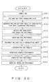
- FIG. 20 is a flowchart showing the operation of the pattern extraction apparatus according to the embodiment of the present invention.
- the labelling process is performed on an input image (step S51).
- the coordinate information about the enclosing rectangle of each connected element is obtained in the labelling process.
- the size of a text character is estimated (step S52).
- a histogram relating to the size of the enclosing rectangle of a connected element is generated.
- the histogram is weighted by the frequency and the area of a rectangle. Practically, assuming that the width and the height of a connected element are respectively dx and dy, the histogram of the larger is adopted.
- the following transformation is performed on each value H (i) of the obtained histogram to generate a new histogram H'.
- H' (i) H (i) x H (i) x i x i (where i indicates the size of a rectangle.)
- the point indicating the maximum histogram value refers to the text character size.
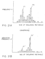
- FIG. 21 shows an example of a histogram for obtaining the size of an enclosing rectangle according to an embodiment of the present invention.
- the text character size when the text character size is estimated using the histogram, the size of the enclosing rectangle corresponding to the peak P1 may be estimated as the text character size. Thus, the text character size may be mistakenly estimated.
- the histogram shown in FIG. 21A is weighted by the size of the enclosing rectangle in FIG. 21B, the histogram value H of the peak P1 indicating a small enclosing rectangle is smaller than the histogram value H of the peak P2 indicating a large enclosing rectangle.
- the histogram shown in FIG. 21B it is possible to estimate the value of the peak P2' corresponding to the size of the text character to be larger than the value of the peak P1' corresponding to the size of the enclosing rectangle of a part of the character before integration.
- mistakenly estimating the size of the enclosing rectangle corresponding to the peak P1' as the text character size can be avoided.
- the text character size can be correctly estimated.
- a text character rectangle candidate is selected from all rectangles.
- the width of a connected element is dx
- the height of the connected element is dy
- the size of the text character is c
- the threshold is ⁇
- a rectangle satisfying the following equation is defined as a candidate for a text character rectangle.
- a projection of a candidate for a text character rectangle is made. That is, when the number of the candidate for a text character rectangle is n, and the coordinates of the upper left point and the lower right point of the rectangle are respectively (x1, y1) and (x2, y2), the number n is stored in the range from x1 to x2 along the x coordinate axis and in the range from y1 to y2 along the y coordinate axis.
- a projection table for a candidate for a text character rectangle is generated.
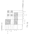
- FIG. 22 shows an example of the method of projecting a rectangle number according to an embodiment of the present invention.
- each of the rectangle numbers 1 through 6 is projected on the x and y coordinate axes. For example, at the points where the x coordinates are 4 through 6, the enclosing rectangles having the rectangle numbers 1 and 6 are positioned. As a result, the rectangle numbers 1 and 6 are projected on the x coordinates 4 through 6. At the points where the x coordinates are 7, 8, and 10, the enclosing rectangle having the rectangle number 6 is positioned. As a result, the rectangle number 6 is projected on the x coordinates 7, 8, and 10. At the point where the x coordinate is 9, the enclosing rectangles having the rectangle numbers 2. 4. and 6 are positioned.
- the rectangle numbers 2, 4, and 6 are projected on the x coordinate 9.
- the enclosing rectangles having the rectangle numbers 3 and 5 are positioned.
- the rectangle numbers 3 and 5 are projected on the x coordinate 11.
- the similar processes are performed on the y coordinate.
- a candidate for a headline rectangle is selected (step S54).
- a headline and characters forming a headline are selected. Basically, a portion obtained by multiplying a size of a text character by a predetermined number is defined as a candidate for a headline rectangle.
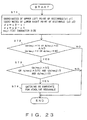
- FIG. 23 is a flowchart showing the method of selecting a candidate for a headline rectangle according to an embodiment of the present invention.
- step S72 it is determined whether or not the following conditions are satisfied. If the conditions are not satisfied, then it is determined that the portion being processed is not a candidate for a headline rectangle, thereby terminating the process. If the conditions are satisfied, then control is passed to step S73. (dx ⁇ moji x 16 or dy > moji x 2) and (dx > moji x 2 or dy ⁇ moji x 16)
- step S73 it is determined whether or not the following conditions, are satisfied. If the conditions are not satisfied, then it is determined that the portion being processed is not a candidate for a headline rectangle, thereby terminating the process. If the conditions are satisfied, then the portion being processed is entered as a candidate for a headline rectangle (step S74). (dx > moji x 3/2 or dy > moji x 3/2) and (dx > moji / 3 or dy > moji / 3)
- step S55 a box rectangle is checked.
- the box rectangle cannot be a headline, and cannot be distinguished from a headline rectangle by size or shape.
- the box rectangle should be removed from all of the boxes. Normally, a character box contains a number of text characters, but a headline rectangle hardly contains text characters. Therefore, the number of candidates for text character boxes is counted in a rectangle to determine whether or not they are box rectangles. That is, the number of candidates for text character boxes in the enclosing rectangle is counted in a target area.
- a candidate for a text character box refers to an area of connected black picture elements enclosed by a rectangle of a text character size.
- the number of text characters in a character box can be efficiently computed using a projection table of candidates for character boxes.
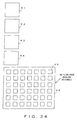
- FIG. 24 shows a method of checking a box according to an embodiment of the present invention.
- enclosing rectangles K1 through K6 are extracted, and the enclosing rectangles K1 through K5 are selected as candidates for headline character boxes.
- the enclosing rectangles K1 through K4 enclose headline characters
- the enclosing rectangle K5 is a character box enclosing text characters.
- a group of headline character enclosing rectangles include a rectangle enclosing non-headline characters.
- the headline characters cannot be correctly extracted, and therefore, it is necessary to remove the enclosing rectangle K5 from the candidates for headline character boxes.
- the enclosing rectangle K5 contains a number of the enclosing rectangles K6 of a text character size whereas the enclosing rectangles K1 through K4 do not contain an enclosing rectangle of a text character size
- the enclosing rectangles K5 containing a number of the enclosing rectangles K6 of a text character size should be removed from the candidates for headline character boxes so that only the enclosing rectangles K1 through K4 can be correctly selected as candidates for headline character boxes.
- step S56 Performed next is the partially-overlapping nest integrating process.
- Candidates for headline character boxes may contain enclosing rectangles of connected elements comprising a part of a drawing or a photograph. These enclosing rectangles may be integrated into other correct headline rectangles, thereby causing an undesired influence.
- the undesired influence on the extraction of a headline rectangle should be reduced by absorbing or integrating the enclosing rectangle forming part of a drawing or a photograph into a larger rectangle.
- rectangles forming part of a drawing or a photograph often overlap each other, which is a clue to easily detecting the rectangles. Therefore, the overlap level of enclosing rectangles is computed.
- the level exceeds a predetermined threshold, it is determined that the enclosing rectangle is obtained as a part of a drawing or a photograph. Then, the overlapping nest integrating process is performed only on the rectangle.
- the overlap level of an enclosing rectangle indicates how many other enclosing rectangles overlap the enclosing rectangle.
- FIG. 25 shows the overlapping nest integrating process.
- FIG. 26 shows the partially-overlapping nest integrating process.
- enclosing rectangles K21 through K26 are generated.
- the enclosing rectangle K22 overlaps two enclosing rectangles K21 and K23. Therefore, the overlap level of the enclosing rectangle 22 is 2. Since the enclosing rectangle 23 overlaps four enclosing rectangles K22, and K24 through K26, the overlap level of the enclosing rectangle 23 is 4.
- the enclosing rectangle 27 containing the enclosing rectangles K22 through K26 is generated as shown in FIG. 26B, and the enclosing rectangles K21 and K27 are not integrated.
- the enclosing rectangle K21 is a headline character box
- the enclosing rectangles K22 through K26 enclose the background pattern, and the overlapping nest integrating process is performed without considering the overlap level, then all the enclosing rectangles K21 through K26 are integrated, the headline character boxes are lost, and the headline character area cannot be extracted.
- the enclosing rectangles K21 through K26 separately exists, and the enclosing rectangles K22 through K26 of the background pattern against headline characters may be selected as candidates for headline rectangles.
- the enclosing rectangles K22 through K26 of the background pattern against headline characters are selected as candidates for headline rectangles, headline characters cannot be correctly extracted.
- the enclosing rectangles K21 through K26 to be processed in the overlapping nest integrating process are selected based on the overlap level, and the overlapping nest integrating process is performed only on the enclosing rectangles K22 through K26.
- the enclosing rectangles K22 through K26 of the background pattern against headline characters are absorbed in the enclosing rectangle K27, thereby preventing the enclosing rectangles K22 through K26 from being selected as candidates for headline rectangle.
- the enclosing rectangle K21 of the headline characters can be maintained as is, thereby improving the precision in extracting headline characters.
- the overlap level can be computed as described below.
- a projection table of candidates for headline rectangles is generated by the method shown in FIG. 22. Then, the overlap level is computed for each picture element of a candidate for a headline rectangle by referring to a headline rectangle number based on the x coordinate axis projection table and the y coordinate axis projection table.
- step S57 Performed next is the rectangular integration (step S57).
- headline rectangles are integrated. First, the vicinity area of a target headline rectangle is defined, and another headline rectangle a part of which is contained in the vicinity area is checked. Then, it is determined whether or not the target headline rectangle can be integrated into the headline rectangle in the vicinity area. At this time, the vicinity area is defined and the integration conditions are determined for both vertically and horizontally printed characters.
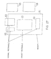
- FIG. 27 shows an example of a vicinal rectangle.
- the vicinity area H1 is set within a predetermined range of the enclosing rectangle K31.
- the enclosing rectangle K32 through K34 within the vicinity area H1 are selected as candidates for enclosing rectangles to be integrated into the enclosing rectangle K31.
- the enclosing rectangles K35 and K36 are removed from the candidates for the enclosing rectangles to be integrated into the enclosing rectangle K31.
- FIG. 28 is a flowchart showing the vicinity integrating process.
- a set of rectangles are input (step S81) to establish a link between rectangles (step S82).
- a target rectangle is set first (step S91), and an enclosing rectangle in the vicinity of the target rectangle is extracted, thereby determining the vicinal rectangle of the target rectangle (step S92).
- the possibility of the integration of the target rectangle and the vicinal rectangle is determined. If it is determined that the target rectangle and the vicinal rectangle can be integrated, a link is established.
- step S83 a set of very large linked rectangles are extracted. Rectangles belonging to the set of very large rectangles are deleted from the set of rectangles input in step S81, and an enclosing rectangle of the set of very large rectangles is added to the set of rectangles (step S84).
- step S58 Performed next is the overlapping rectangle removing process.
- one of overlapping rectangles is deleted to avoid double rectangles in the integrated headline rectangles.
- FIG. 29 shows an example of double rectangles .
- the vicinal area H11 is set around the enclosing rectangle K41. If the enclosing rectangle K42 in the vicinal area H11 is extracted, and it is determined that the enclosing rectangles K41 and K42 can be integrated, then the enclosing rectangle K43 including the enclosing rectangles K41 and K42 is generated.
- the vicinal area H12 is set around the enclosing rectangle K41. If the enclosing rectangle K42 in the vicinal area H12 is extracted, and it is determined that the enclosing rectangles K41 and K42 can be integrated, then the enclosing rectangle K43 including the enclosing rectangles K41 and K42 is generated.
- step S59 a check is made on a box rectangle.
- this box rectangle check it is determined whether or not an obtained headline rectangle is a box rectangle using a projection table, and a box rectangle is removed from headline rectangles.
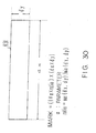
- a headline rectangle is marked (step S60).
- a mark is assigned to an obtained headline rectangle based on its size and shape.
- FIG. 30 shows the method of marking a headline rectangle.
- the titles can be assigned priority numbers for output.
- a character recognizing process is performed for each group to assign a character string level and extract a group of consistent combinations. Therefore, a character string can be extracted from a complicated image comprising a background pattern containing a combination of white and black portions, various types of fonts, a color document, a plurality of lines, a combination of vertical and horizontal character strings, and a compound of them.
- a combination of portions, whose areas do not overlap each other based on the recognition results of the patterns obtained from an input image and its black/white inverse image, is defined as an extraction result of the pattern from the input image.
- the color of a character is determined by the number of black character candidates and white character candidates. Therefore, when it is determined that the character color is black, only the connected elements of the input image is to be processed thereafter and a black character can be correctly recognized, but a white character against the black background cannot be recognized.
- a character string can be extracted with precision from a complicated image comprising a background pattern containing a combination of white and black portions, various types of fonts, a color document, a plurality of lines, a combination of vertical and horizontal character strings, and a compound of them.
- the frequency of an enclosing rectangle is weighted by the area of the enclosing rectangle. Therefore, even if a character is formed by a plurality of separate strokes, not processed in the overlapping nest integrating process, and therefore an enclosing rectangle generated for each stroke remains as is, the enclosing rectangle formed by a part of one character is smaller than an enclosing rectangle formed for an entire character. As a result, the evaluation of the frequency of the enclosing rectangle formed by a part of one character can be set lower, and the influence of the size of a part of a character can be reduced in estimating the size of a character. Therefore, the character size can be estimated with high precision even when the overlapping nest integrating process is not performed.
- the number of text characters in a character box is counted. Therefore, when headline characters are extracted from newspapers, etc., and when a rectangular character box enclosing text characters exists near the headline characters, only the box rectangle can be extracted, thereby distinguishing the rectangular character box from the enclosing rectangle for the headline characters. As a result, only the headline characters can be extracted with high precision.
- a rectangle number assigned to an enclosing rectangle may be projected to each coordinate set on the input image. Therefore, an enclosing rectangle existing in another enclosing rectangle can be easily extracted. As a result, even if a rectangular character box enclosing text characters and headline characters coexist, only the box rectangle can be quickly extracted.
- an overlapping nest integrating process is partially performed. Therefore, the overlapping nest integrating process is performed only on the enclosing rectangles having a high overlap level, and the process can be omitted on enclosing rectangles having a low overlap level.
- an enclosing rectangle of headline characters can be prevented from being lost by enclosing rectangles being integrated on the entire screen, and a part of a drawing or a photograph having a high overlap level can be absorbed or integrated into a larger rectangle.
- an enclosing rectangle of a part of a drawing or a photograph remains as is to be mistakenly extracted as headline characters or mistakenly integrated into a rectangle as headline characters.
- headline characters can be extracted with high precision even if the headline characters coexist with a drawing, a photograph, etc.
- a rectangle number assigned to an enclosing rectangle is projected to each coordinate set on the input image. Therefore, enclosing rectangles overlapping each other can be easily extracted, thereby quickly computing the overlap level of the enclosing rectangles.
- color also includes black and white.
Landscapes
- Engineering & Computer Science (AREA)
- Computer Vision & Pattern Recognition (AREA)
- Physics & Mathematics (AREA)
- General Physics & Mathematics (AREA)
- Multimedia (AREA)
- Theoretical Computer Science (AREA)
- Artificial Intelligence (AREA)
- Computer Graphics (AREA)
- Geometry (AREA)
- Character Input (AREA)
- Character Discrimination (AREA)
- Image Analysis (AREA)
Description
- The present invention relates to image recognizing technology for reading documents, drawings, etc., and more specifically to pattern extraction technology for extracting a pattern and in particular a character string such as a headline from an image.
- When a document is electronically filed, it is indispensable to assign a keyword to the document. However, it is a very annoying process for a user. Therefore, it is significant to successfully automate this process and efficiently perform an electronic filing process.
- In newspapers and magazines, it is the most efficient to automatically extract a headline, recognize characters forming the headline, and define it as a keyword because a headline indicates a lot of characteristics of the contents of a document, and can be easily retrieved from the document.
- As a result, technology of shortening the time taken to extract a keyword, and of correctly extracting a keyword (for example, JP-A- 4-287168 which discloses a method of automatically extracting a keyword from a file) has been developed.
- In this method, it is assumed that the descriptions of a drawing, a photograph, and a table are positioned at the top or foot of each of them to be described. Thus, the descriptions can be extracted as a character string or a character string area, and the characters forming the descriptions are recognized and entered as a keyword.
- Also, technology of extracting a character string from an image (for example, JP-A- 8-293003 which discloses a character string extracting method and a character string extraction apparatus based on the method, a character string recognizing apparatus and a character string recognizing system) has been developed.
- In this example, all characters in the image are extracted, continuous characters are grouped as a character string, the feature amount of each group is compared with an entered feature amount model, discriminated, and extracted as a character string. Continuous characters refers to a character string, and a feature amount refers to a type and size of a character such as a kanji (Chinese character), a numerical character, etc.
- Thus, there are various documents and drawings to be treated in an electronic filing process, and there are various image recognition technology. When a character string is extracted from an image, the most popular method is to process a headline which has its background as often seen in newspapers.
- First, it is determined whether an input image contains vertically arranged characters or horizontally arranged characters. Then, a labelling process is performed on the input image and its black/white inverse image to obtain connected elements having a series of picture elements in the same color.
- Next, a character candidate is found based on the size, thickness, and relative position of each connected element.
- The character candidate obtained from the connected element of an input image is referred to as a black character candidate, and the character candidate obtained from the connected element of an inverse image is referred to as a white character candidate. The color of characters is determined from the number of black character candidates and white character candidates. When the character color is black, only the connected elements of an input image are to be processed in the subsequent steps. When the character color is white, only the connected elements of the black/white inverse image are to be processed thereafter.
- Next, a character string area is obtained after merging the connected elements to be processed. The connected element which is contained in the character string area and is equal to or larger than a threshold in thickness is extracted as a character element. The threshold is a value indicating a constant ratio to the maximum value in thickness of a connected element. Finally, the connected element extracted as a character element is generated as an image, and is defined as a character string in a character recognizing process.
- To correctly extract a headline, precise integration technology for a black picture element area belonging to the same character string is required.
- The following proposed method relates to this technology.
- After performing a pre-process such as adjusting a tilt, removing a character-box line, etc., the entire image is labelled, and an overlapping nest integrating process is performed on the obtained black picture element connection areas. Then, the character size of the text of the entire document is determined from the obtained black picture element connection area. Based on the value, the attribute of each connection area is determined. When it is determined that the attribute of a rectangle is a character, vertical or horizontal integration is repeated on the rectangle, thereby defining a character string.
- However, in the proposed technology, the character color is determined during the character extracting process, and the character line width is fixed to a standard value. Furthermore, a character string area is set in line units (or in column units). Therefore, it has been a problem that it is quite difficult to extract a character string from a complicated image comprising a background pattern containing a combination of white and black portions, various types of fonts, a color document, a plurality of lines, a combination of vertical and horizontal character strings, and a compound of them.
- Furthermore, the relationship between black character candidates and white character candidate in number is not a reliable criterion for determining a character color. When the character color is determined during the character extracting process, the determination is irrevocable if it is mistakenly made, thereby failing in the final character recognition.
- Additionally, when the character line width is fixed to a standard value, a character element printed by a comparatively thin line can be easily lost, thereby failing in the final character recognition.
- Furthermore, since the overlapping nest integrating process is performed on black picture element connection areas in the prior-proposed technology, portions which should not be originally integrated are sequentially integrated, thus finally and incorrectly integrating the entire document.
- For example, when the tilt of the entire document cannot be adjusted, or the character-box line cannot be completely removed, the entire document can be integrated in the overlapping nest integrating process.
- FIG. 1 shows an example of integrating the entire document in the proposed overlapping nest integrating process.
- In FIG. 1A, it is assumed that the enclosing rectangles K61 through K65 of the connected elements have been obtained from an input image. When the overlapping nest integrating process is performed on the enclosing rectangles K61 through K65 of the connected elements, the enclosing rectangle K61 and the enclosing rectangle K62 are integrated because they overlap each other. As a result, as shown in FIG. 1B, an enclosing rectangle K66 enclosing the enclosing rectangle K61 and the enclosing rectangle K62 is generated. When the enclosing rectangle K66 is generated, the enclosing rectangle K66 overlaps the enclosing rectangle K63. Therefore, they are integrated, and the enclosing rectangle K67 encompassing the enclosing rectangle K66 and the enclosing rectangle K63 is generated as shown in FIG. 1C. When the enclosing rectangle K67 is generated, the enclosing rectangle K67 overlaps the enclosing rectangle K64. Therefore, they are integrated. Similarly, all enclosing rectangles K61 through K65 shown in FIG. 1A are integrated, and the enclosing rectangle K68 encompassing the enclosing rectangles K61 through K65 is generated as shown in FIG. 1D.
- Also, there is the problem that it takes too long a time to perform the overlapping nest integrating process when there is a headline with a photograph, drawing, or texture.
- US-A-5 757 957 discloses a pattern extraction apparatus and method according to the preamble of each of the corresponding independent claims. The apparatus/method generates a histogram of frequency of occurrence of rectangle as a function of rectangle-height, and a value t is defined as a value proportional to the total number of rectangles. The largest rectangle height among those of which the occurrence frequencies exceed t is taken as the reference character size.
- An embodiment of the present invention, relating to the technology of recognizing an image by reading a document, drawings, etc., may provide a pattern extraction apparatus for extracting a character string from a complicated image, and recognizing even a thin character line and recognizing a character without mis-recognizing a character color.
- According to a first aspect of the present invention, there is provided a pattern extraction apparatus comprising:
- connected element extraction means for extracting connected elements of an input image including characters;
- enclosing rectangle generation means for generating an enclosing rectangle of the connected elements;
- histogram generation means for generating a histogram showing the frequency of occurrence in the input image of enclosing rectangles of various sizes; and
- character size estimation means for estimating a size of an enclosing rectangle indicating a maximum value of the histogram as the character size of the input image; characterized in that
-
- According to a second aspect of the present invention, there is provided a pattern extraction method comprising the steps of:
- extracting connected elements of an input image including characters;
- generating an enclosing rectangle of the connected elements;
- generating a histogram showing the frequency of occurrence in the input image of enclosing rectangles of various sizes; and
- estimating a size of an enclosing rectangle indicating a maximum value of the histogram as the character size of the input image; characterized in that
- said histogram generation means generates said histogram by weighting the frequency of each enclosing rectangle by the size of the enclosing rectangle.
-
- According to a third aspect of the present invention, there is provided a computer-readable storage medium storing a program causing a computer to execute a pattern extraction method comprising:
- extracting connected elements of an input image including characters;
- generating an enclosing rectangle of the connected elements;
- generating a histogram showing the frequency of occurrence in the input image of enclosing rectangles of various sizes; and
- estimating a size of an enclosing rectangle indicating a maximum value of the histogram as the character size of the input image; wherein said histogram generation step generates said histogram by weighting the frequency of each enclosing rectangle by the size of the enclosing rectangle.
-
- In prior-proposed technology, when characters formed by black picture elements and white characters against the black background co-exist in a headline of newspapers, etc., the color of a character is determined by the number of black character candidates and white character candidates. Therefore, when it is determined that the character color is black, only the connected elements of the input image are to be processed thereafter and a black character can be correctly recognized, but a white character against the black background cannot be recognized. Similarly, when it is determined that the character color is white, only the connected elements of the black/white inverse image are to be processed for character recognition and a white character against the black background can be correctly recognized, but a black character cannot be recognized. By using the present invention, the above-described mis-recognition can be avoided. Thus, a character string can be extracted with precision from a complicated image comprising a background pattern containing a combination of white and black portions, various types of fonts, a color document, a plurality of lines, a combination of vertical and horizontal character strings, and a compound of them.
- In the present invention, even if a character is formed by a plurality of separate strokes, not processed in the overlapping nest integrating process, and therefore an enclosing rectangle generated for each stroke remains as is, the enclosing rectangle formed by a part of one character is smaller than an enclosing rectangle formed for an entire character. As a result, the evaluation of the frequency of the enclosing rectangle formed by a part of one character can be set lower, and the influence of the size of a part of a character can be reduced in estimating the size of a character. Therefore, the character size can be estimated with high precision even when the overlapping nest integrating process is not performed.
- Preferably, the apparatus of the present invention is applied to an input image including headline characters to be extracted and text characters, whereby the enclosing rectangles include at least one headline character box and at least one text character box, the apparatus further comprising: grouping means for selecting, from the enclosing rectangles, candidates for headline character boxes; counting means for counting, in each of the enclosing rectangles which are candidates for headline character boxes, the number of smaller enclosing rectangles of the size of text characters contained in the enclosing rectangle; and removing means for removing, from the candidates for headline character boxes, any enclosing rectangle containing a predetermined number or more of the smaller enclosing rectangles.
- Thus, when headline characters are extracted from newspapers, etc., and when a box rectangle enclosing text characters exists near the headline characters, it is possible to distinguish the box rectangle from the enclosing rectangle for the headline characters. As a result, only the headline characters can be extracted with high precision.
- Preferably, in the apparatus of the present invention, each enclosing rectangle has a position defined by co-ordinates in x and y co-ordinate axes of the input image, and the apparatus further comprises: projecting means for assigning a rectangle number identifying each of the enclosed rectangles, and projecting each of the rectangle numbers onto said x and y co-ordinate axes to form a projection table for candidates for a text character box in which each rectangle number is stored at the co-ordinates of the corresponding enclosing rectangle.
- Thus, smaller enclosing rectangles existing in another enclosing rectangle can be easily identified. As a result, even if enclosing rectangles are extracted which contain text characters, in addition to an enclosing rectangle containing headline characters, only the enclosing rectangle containing headline characters can be quickly extracted.
- Reference is made, by way of example only, to the accompanying drawings in which Figures 20 to 23 are particularly relevant to the present invention, and in which:
- FIG. 1 shows an example of integrating rectangles of the entire document in a proposed overlapping nest integrating process;
- FIG. 2 is a block diagram showing the configuration of a pattern extraction apparatus useful for understanding the present invention;
- FIG. 3 is a block diagram showing the configuration of another pattern extraction apparatus useful for understanding the present invention;
- FIG. 4 is a block diagram showing the system configuration of a pattern extraction apparatus to which the present invention may be applied;
- FIG. 5 shows the operation of a character extraction apparatus useful for understanding the present invention;
- FIG. 6 is a block diagram showing the configuration of the character extraction apparatus for performing the operation of FIG. 5;
- FIG. 7 is a flowchart showing the operation of the character extraction apparatus of FIG. 6;
- FIG. 8 shows a labelling process of FIG. 7;
- FIG. 9 is a flowchart showing a grouping process of FIG. 7, which is useful for understanding the present invention;
- FIG. 10 shows an example of connected elements and enclosing rectangles;
- FIG. 11 is a flowchart showing a method of limiting the connected elements;
- FIG. 12 shows the vicinity of the connected elements;
- FIG. 13 shows the familial similarity of the connected elements;
- FIG. 14 shows a method of computing the character recognition level of a group;
- FIG. 15 shows an association graph and clique;
- FIG. 16 is a flowchart showing a method of extracting a group not overlapping another group of connected elements;
- FIG. 17 shows a method of linking the connected elements;
- FIG. 18 shows examples of clique groups and non-clique groups;
- FIG. 19 shows a method of computing the evaluation value of a combination;
- FIG. 20 is a flowchart showing the operations of a pattern extraction apparatus according to an embodiment of the present invention;
- FIG. 21 shows an example of a histogram for obtaining the size of the enclosing rectangle according to an embodiment of the present invention;
- FIG. 22 shows an example of a projection table of rectangle numbers according to an embodiment of the present invention;
- FIG. 23 is a flowchart showing the method of selecting a candidate for a headline rectangle according to an embodiment of the present invention;
- FIG 24 shows the method of checking a box rectangle;
- FIG. 25 shows overlapping nest integration;
- FIG. 26 shows partially-overlapping nest integration;
- FIG. 27 shows an example of a rectangle in the vicinity (vicinal rectangle);
- FIG. 28 is a flowchart showing the vicinity integrating process;
- FIG. 29 shows an example of overlapping rectangles; and
- FIG. 30 shows a method of marking a headline rectangle.
-
- Before describing an embodiment of the present invention, some apparatus and techniques useful for understanding the present invention will be described by way of background explanation.
- FIG. 2 is a block diagram showing the configuration of a pattern extraction apparatus useful for understanding the present invention.
- In FIG. 2, an inverse
image generation unit 1 generates an inverse image obtained by changing the label of an input image. Arecognition unit 2 performs a pattern recognizing process on a pattern extracted from the inverse image generated by the inverseimage generation unit 1. Anoutput unit 3 outputs a nonoverlapping combination of an area of a pattern extracted from the input image and an area of a pattern extracted from the inverse image generated by the inverseimage generation unit 1 as a consistent combination from among the recognition results from therecognition unit 2. - Thus, even if characters formed by black picture elements and white characters against the black background co-exist in a headline of newspapers, etc., the recognizing process can be performed on both characters formed by black picture elements and white characters against the black background. The recognition results of the characters of black picture elements can be output in combination with the recognition results of the white characters against the black background.
- In prior-proposed technology, the color of a character is determined by the number of black character candidates and white character candidates. Therefore, when it is determined that the character color is black, only the connected elements of the input image is to be processed thereafter and a black character can be correctly recognized, but a white character against the black background cannot be recognized. Similarly, when it is determined that the character color is white, only the connected elements of the black/white inverse image is to be processed for character recognition and a white character against the black background can be correctly recognized, but a black character cannot be recognized. By using the FIG, 2 apparatus, the above described mis-recognition can be avoided. Thus, a character string can be extracted with precision from a complicated image comprising a background pattern containing a combination of white and black portions, various types of fonts, a color document, a plurality of lines, a combination of vertical and horizontal character strings, and a compound of them.
- FIG. 3 is a block diagram showing the configuration of another pattern extraction apparatus useful for understanding the present invention.
- In FIG. 3, a connected element extraction unit 11 extracts connected elements of an input image. An enclosing rectangle generation unit 12 generates an enclosing rectangle of connected elements extracted by the connected element extraction unit 11. An overlap level evaluation unit 13 computes the number of enclosing rectangles overlapping the enclosing rectangle generated by the enclosing rectangle generation unit 12. An overlapping nest integrating unit 14 performs the overlapping nest integrating process based on the computation result of the overlap level evaluation unit 13.
- Thus, the overlapping nest integrating process can be partially performed. That is, the process can be performed only on an enclosing rectangle having a high overlap level, and can be suppressed on an enclosing rectangle having a low overlap level. As a result, the enclosing rectangle of headline characters can be prevented from being lost by enclosing rectangles being integrated on the entire screen.
- Furthermore, a part of a drawing or a photograph having a high overlap level can be absorbed or integrated into a larger rectangle. Thus, it can be avoided that an enclosing rectangle of a part of a drawing or a photograph remains as is to be mistakenly extracted as headline characters or mistakenly integrated into a rectangle as headline characters. As a result, headline characters can be extracted with high precision even if the headline characters coexist with a drawing, a photograph, etc.
- FIG. 4 is a block diagram showing the system configuration of the character string extraction apparatus of FIG. 2 or FIG. 3, which is also applicable to the present invention.
- In FIG. 4, 21 is a central processing unit (CPU) for performing an entire process. 22 is read-only memory (ROM). 23 is random-access memory (RAM). 24 is a communications interface. 25 is a communications network. 26 is a bus. 27 is an input/output interface. 28 is a display for displaying, for example, recognition results of headline characters, etc. 29 is a printer for printing, for example, recognition results of headline characters, etc. 30 is memory for temporarily storing data read by a
scanner 31. 31 is a scanner for reading an input image, etc. 32 is a keyboard. 33 is a driver for driving a storage medium. 34 is a hard disk. 35 is an IC memory card. 36 is a magnetic tape. 37 is a floppy disk. 38 is an optical disk such as CD-ROM, DVD-ROM, etc. - For example, a program for performing a pattern extracting process is stored in a storage medium such as the
hard disk 34,IC memory card 35,magnetic tape 36,floppy disk 37,optical disk 38, etc. Headline characters, etc. can be extracted from a document image of, for example, newspapers, magazines, etc. by reading a program, etc. for performing a pattern extracting process from the storage media to theRAM 23. Furthermore, a program, etc. for performing a pattern extracting process can be stored in theROM 22. - Additionally, a program, etc. for performing a pattern extracting process can be retrieved from the
communications network 25 through thecommunications interface 24. As thecommunications network 25 connected to thecommunications interface 24, a LAN (local area network), a WAN (wide area network), the Internet, an analog telephone network, a digital telephone network (ISDN: integral service digital network), a wireless communications network such as a PHS (personal handy system), satellite communications, etc. can be used. - When a program for performing a pattern extracting process is activated, the
CPU 21 labels an input image read by thescanner 31, and generates an enclosing rectangle for connected elements assigned the same labels. Then, it checks the overlap level of each enclosing rectangle, and performs the overlapping nest integrating process on the enclosing rectangles overlapping each other at a high overlap level. Next, it groups the enclosing rectangles treated in the overlapping nest integrating process, extracts headline characters from among the grouping results, and outputs the extraction result on thedisplay 28 or theprinter 29. - FIG. 5 shows the operation of a character extraction apparatus useful for understanding the present invention.
- In FIG. 5A, it is assumed that characters of black picture elementsarranged in two lines enclosed by a black character box, and white characters
 , vertically arranged against the black background have been input as an input image, and that the character string
- First, connected elements containing a series of picture elements of the same color are extracted from the input image based on the color of picture elements.
- When the input image is a color image, the connected elements are extracted for each color. Since the input image shown in FIG. 5A is a black-and-white binary image, the connected elements containing black picture elements and white picture elements are extracted also from the black/white inverse image. The inverse image is obtained by exchanging the colors between the background of the input image and the characters as shown in FIG. 5A.
- In the connected element extraction unit, a different label is assigned to each group of connected elements of black picture elements in the input image, and a different label is assigned to each group of connected elements of black picture elements in the black/white inverse image.
- Then, in the input image and its inverse image, connected elements probably containing common character strings or character string groups based on the relative positions and the similarity in thickness among connected elements are grouped.
- The similarity of connected elements in thickness refers to the ratio of the number of boundary picture elements to the total number of picture elements of connected elements. Common character strings or character string groups refer to a set of character strings representing the same meanings .
- As a result, since the input characters
 ,
, , and
, and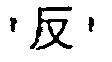 are grouped as a group a. The character box enclosing the input image, that is, the characters
- Similarly, since the black picture element area corresponding to the background against the white characters
 , and
, and are grouped as a group b1.
- The group a is formed by relatively small characters against a white background area, and the group b is formed by relatively large white characters against a black background area. However, at first, the group b is not recognized as white characters against the black background. It is only recognized that the group a contains characters against a white background, and that the group b is blackish as a whole. Therefore, the characters
- The group a1 is formed by relatively small white characters against a black background area, and the group b1 is formed by relatively large characters against a white background area. However, at first, the group b1 is not recognized as white characters against the black background. It is only recognized that the group a1 is blackish as a whole, and that the group b1 contains characters against the white background. Therefore, the characters
- After grouping the characters as described above, the character recognizing process is performed on each group. A sum of the inverse numbers of the distance values of the first character candidates of the characters obtained as the recognition results is defined as the character recognition level of the group. Therefore, if the character recognition level of a group is high, there is a strong possibility that the group is a character string to be extracted. The evaluation value of a group is obtained by weighting the character recognition level of a group by the area of the rectangular area enclosing the group.
- Then, the evaluation value is obtained for the combinations of all groups to define the evaluation value of a combination. When groups are combined, only the groups whose rectangular areas enclosing the groups are not overlapping each other are associated, and all combinations of the groups whose rectangular areas enclosing the groups are not overlapping each other are obtained.
- FIG. 5B shows the combination of groups whose rectangular areas enclosing the groups are not overlapping each other.
- As shown in FIG. 5B, since the rectangular area enclosing the group a shown in FIG. 5A does not overlap the rectangular area enclosing the group b1, it can be combined with the group b1. However, since the rectangular area enclosing the group a overlaps the rectangular area of the group b or a1, the group a is not combined with the group b or a1.
- On the other hand, since the rectangular area enclosing the group b overlaps any rectangular area enclosing the group a, a1, or b1, it cannot be combined with any of the groups a, a1, and b1.
- Therefore, the combinations of the groups a and b, a and a1, b and a1, b and b1, and a1 and b1 are removed from all combinations. As a result, only the combination of the groups a and b1 remains. The combinations to be removed are indicated by the broken lines in FIG. 5B. The evaluation values are computed for all combinations of groups connected by solid lines. As a result, the combination of the group having the highest evaluation value is extracted as a character string.
- FIG. 5C shows a computation result.
- In FIG. 5C, the combination of groups a and b is selected. After the character recognizing process is performed on the pattern extracted from the group a, the character string
- If the character recognizing process is performed on the group b, then the character string
- Therefore, if the recognizing process is performed using only the pattern extracted from the input image shown in FIG. 5A, then the character string
- If the character recognizing process is performed on the group a1, then the character string
- Therefore, if the recognizing process is performed using only the pattern extracted from the inverse image shown in FIG. 5A, then the character string
- On the other hand, by means of the character extraction apparatus useful for understanding the invention, the character recognizing process is performed using both the pattern extracted from the input image and the pattern extracted from the inverse image. The character string
- FIG. 6 is a block diagram showing the configuration of the character extraction apparatus for implementing the above operation.
- In FIG. 6, a character string extraction apparatus 41 comprises a connected
element extraction unit 42, a grouping unit 43, acharacter recognition unit 44, a combination evaluation unit 45, and a character string extraction unit 46. - The connected
element extraction unit 42 extracts connected elements containing a series of picture elements of the same color based on the color of the picture elements in the input image. If the input image is a color image, then connected elements are extracted for each color. If the input image is a monochrome binary image, then black and white picture elements of the connected elements in an inverse image are also extracted for each color. - The grouping unit 43 groups connected elements which possibly have common character strings or character string groups based on the relative positions between the connected elements and the similarity in thickness of connected elements.
- The
character recognition unit 44 performs the character recognizing process for each group and obtains the character recognition level of a group. The combination evaluation unit 45 obtains an evaluation value of a group, and then obtains an evaluation value of a combination. The character string extraction unit 46 extracts as a character string a combination of groups having the highest evaluation value of a combination. - Thus, the character string extraction apparatus 41 shown in FIG. 6 groups connected elements based on the similarity, performs the character recognizing process for each group, assigns a character string level to each group, and extracts a combination of consistent groups. Therefore, a character string can be extracted from a complicated image such as a background pattern containing black and white picture elements, a color document, etc.
- Furthermore, the character string extraction apparatus 41 shown in FIG. 6 and the storage medium do not determine a color during the extracting process, do not assume a character string area, or do not determine the line width of a standard character in the extracting process, thereby improving the precision in extraction of character string.
- The character string extraction apparatus 41 of FIG. 6 is described in detail by referring to the attached drawings. As an example of use of the character string extraction apparatus 41, a character string is extracted from a monochrome binary image such as a headline of newspapers, etc.
- FIG. 7 is a flowchart showing the operation of the character extraction apparatus.
- In FIG. 7, an image is input in step S1, and control is passed to step S2. In step S2, a white/black inverse image is generated against the input image. Then, an input image process and an inverse image process are concurrently performed. When the input image process is performed, control is passed to step S3. When the inverse image process is performed, then control is passed to step S6.
- When the input image and its inverse image are obtained, a labelling process is performed to obtain respective connected elements. In step S3, a labelling process is performed on the input image. In step S6, a labelling process is performed on the inverse image.
- After the labelling process for the input and inverse images, the respective connected elements are grouped. As shown in FIG. 7, the connected elements of the input image are grouped in step S4, and the connected elements of the inverse image are grouped in step S7.
- After the grouping process for the input and inverse images, the character recognizing process is performed on both groups. The character recognizing process is performed on the groups of the input image in step S5, and the character recognizing process is performed on the groups of the inverse image in step S8.
- After the character recognizing process on the input and inverse images, control is passed to step S9. In step S9, groups having enclosing rectangular areas overlapping each other are removed from the combinations of groups, and the consistent combinations are all counted.
- In step S10, each of the candidates for combinations is evaluated based on the evaluation value. The evaluation value of each group is a function between the character recognition level of each group and the area of the rectangular area enclosing each group. The evaluation value of a combination is obtained by combining the evaluation values of groups in a consistent combination.
- Then, in step S11, a character string corresponding to the group having the highest evaluation value is extracted, and the process terminates.
- FIG. 8 shows the labelling process referred to in FIG. 7.
- In FIG. 8, a white characteragainst the black background contains four connected elements R1 through R4 respectively assigned the
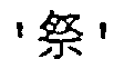
numbers 1 through 4. Thus, identifying connected elements formed by a series of picture elements of the same color (white picture elements in FIG. 4) by numbers, etc. as shown in FIG. 8 is referred to as 'labelling'. - FIG. 9 is a flowchart showing the grouping process of FIG. 7.
- In FIG. 9, a candidate for a character element is selected in step S21. In step S21, target connected elements are limited. In this example, connected elements whose enclosing rectangle is equal to or smaller than a standard size are removed to be set as those not to be processed in the subsequent process because they cannot be candidates for character elements. Then, control is passed to step S22.
- In step S22, the vicinity of connected elements is set. The vicinity refers to an area formed by encompassing the enclosing rectangle of connected elements by a frame of an approximate size. When a part of a connected element is in the vicinity of another connected element, it is referred to as a vicinal connected element. Then, control is passed to step S23.
- In step S23, the connected element is linked to its vicinal connected element. Linking refers to associating a connected element with its vicinal connected element after determining whether the connected element and its vicinal connected element belong to the same character string or the same character string group.
- Connected elements are linked based on the relative position and similarity in thickness of the connected elements. The relative position and similarity in thickness of the connected elements are referred to as familial similarity of the connected elements. The familial similarity of all connected elements and all vicinal connected elements is determined in step S23, and control is passed to step S24.
- In step S24, a connected element linked with its vicinal connected element is extracted as a group.
- The connected elements are linked in various methods. For example, connected elements A, B, and C are linked, but the connected elements A and C may not be directly connected. Similarly, the connected element A is linked to the connected element B, but the connected element B may not be linked to the connected element A.
- The connected elements forming the above described link are referred to as connected elements of arch connection. In step S24, a set of connected elements linked for arch connection is retrieved as a group.
- FIG. 10 shows an example of connected elements and their enclosing rectangle.
- In FIG. 10, the characteris a connected element, and its enclosing rectangle is dx in length in the x direction and dy in the y direction.

- FIG. 11 is a flowchart showing the method of limiting the target connected elements.
- In FIG. 11, the threshold of the length dx in the x direction and the threshold of the length dy in the y direction of the enclosing rectangle of the connected elements are set to th1 and th2. When the length dy in the x direction and the length dy in the y direction are input in step S31 shown in FIG. 11, it is determined in step S32 whether or not the length dy in the y direction is smaller than the threshold th2.
- In step S32, control is passed to step S33 if the length dy in the y direction is smaller than the threshold th2, and control is passed to step S36 if the length dy in the y direction is not smaller than the threshold th2. In step S33, control is passed to step S35 if the length dx in the x direction is larger than the threshold th1 and smaller than the threshold th2, and control is passed to step S34 if the length dx in the x direction is equal to or smaller than the threshold th1 or equal to or larger than the threshold th2.
- In step S34, control is passed to step S35 if the length dy in the y direction is larger than the threshold th1, and control is passed to step S36 if it is not larger than the threshold th1.
- It is assumed in step S35 that the corresponding connected element can be defined as a candidate for a character element. It is assumed in step S36 that the corresponding connected element is not to be processed in the subsequent steps, thereby terminating the process.
- FIG. 12 shows the vicinity of connected elements.
- In FIG. 12, the vicinity is an area formed when the circumference of the enclosing rectangle of connected elements is encompassed by a frame of an appropriate size.
- An appropriate size indicates, as shown in FIG. 12, the space of 1/6 of the width of the character on both sides, and the space of 3/4 of the height of the character above and below the character if the characters are vertically printed. Similarly, the vicinity can be defined for horizontally printed characters.
- In FIG. 12, assuming that the vicinity of the characteris set, the vicinity of
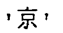
 . Therefore, it is determined that the vicinal connected elements of the character
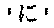 are the characters
 shown in FIG. 12 contains large and small dots forming a net pattern. Since the character
 looks connected at the portion encompassed by the circle, the character
- Assuming that the character
- FIG. 13 shows the familial similarity of the connected elements.
- In FIG. 13, the familial similarity of the connected element depends on the relative positions between the connected elements and the difference in average thickness between the connected elements. The average thickness is represented by the ratio of the number of boundary picture elements to the total number of picture elements of the connected elements, that is, (number of boundary picture elements / total number of picture elements).
- Assuming that, in FIG. 13, the relative positions between the connected element A and its vicinal connected element B are represented by d and nx, and the average thicknesses of the connected element A and its vicinal connected element B are respectively ta and tb, the familial similarity of the vicinal connected element B to the connected element A is represented by the following equation.
- The familial similarity of the vicinal connected element B to the connected element A shown in FIG. 13 is as high as the familial similarity of the connected element C to the connected element B. Therefore, it is determined that the connected elements A, B, and C belong to the same character string. In this example, the familial similarity of the connected element C to the connected element B is considered only in element of thickness.
- FIG. 14 shows the method of computing the character recognition level of a group. In FIG. 14, the character recognition level of a group is represented by a sum of the inverse numbers of the distance values of the first character candidates of the character recognition results after performing a character recognizing process for each group. If a character has a small distance value, it means that the character has a high recognition level.
- Assuming that the character stringis a group A, and the distance values of the first recognition candidates of the characters
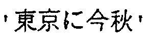
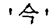 are respectively d1, d2, d3, d4, and d5 as shown in FIG. 14, the character recognition level Ra of the group A is represented by the following equation.
- When target connected elements are limited, there is a strong possibility that the net pattern by dots as the background area against the character string
- FIG. 15 shows an association graph and a clique.
- In FIG. 15, the groups are associated if their rectangular areas do not overlap each other. The concept of an association graph and a clique is used to obtain all combinations of groups whose rectangular areas do not overlap each other.
- That is, an association graph is generated to count consistent combinations, and all cliques, that is, complete graphs, are obtained so that the groups whose rectangular areas overlap each other can be removed from the combination of groups.
- The association graph shown in FIG. 15 is generated, with groups defined as nodes, by connecting via paths (solid lines) the nodes corresponding to the groups whose rectangular areas do not overlap each other. In the association graph, the nodes corresponding to the groups whose rectangular area overlap each other are not connected through paths.
- A clique refers to combinations of consistent nodes. A plurality of cliques are generated from the association graph, and each clique is a complete graph in which all nodes are connected through paths. All combinations of consistent groups can be obtained by obtaining cliques from the association graph.
- Thus, a combination between the group A and the group B shown in FIG. 14 cannot be set even if the provisionally set group B (net pattern) and the group A
- As described above, the evaluation value of a combination of consistent groups can be obtained. As a result of the evaluation, for example, a net pattern as a background area, spots, etc. can be removed from the targets to be processed.
- For example, assuming that an association graph comprising nodes N1 through N8 are generated as shown in FIG. 15, a complete graph is obtained such that paths are connected from each node to all other nodes. For example, since a node N1 is connected to all other nodes N2 through N8 through paths, the node N1 is a node of the clique. Since the node N2 is not connected to the node N8, the node N2 is removed from the nodes of the clique. Since the node N3 is connected to all other nodes N1, N2, and N4 through N8 through paths, the node N3 is a node of the clique. Since the node N4 is connected to all other nodes N1 through N3, and N5 through N8 through paths, the node N4 is a node of the clique. Since the node N5 is connected to all other nodes N1 through N4 and N6 through N8 through paths, the node N5 is a node of the clique. Since the node N6 is not connected to the node N8, the node N6 is removed from the nodes of the clique. Since the node N7 is connected to all other nodes N1 through N6 and N8 through paths, the node N7 is a node of the clique. Since the node N8 is connected to all other nodes N1 through N7, the node N8 is a node of the clique.
- As a result, the clique comprising the nodes N1, N3, N4, N5, N7, and N8 can be extracted. By extracting a clique from an association graph, only the groups whose rectangular areas do not overlap each other can be efficiently extracted.
- FIG. 16 is a flowchart showing a method of extracting groups whose connected elements do not overlap each other.
- In FIG. 16, it is determined whether or not each group is related to all other groups (step S41), and an association graph is generated (step S42). Then, a clique is extracted from an association graph (step S43), and consistent combinations in combinations of groups extracted from input images and groups extracted from inverse images are defined (step S44).
- FIG. 17 shows the method of linking the connected elements.
- In FIG. 17A, assume that the white charactersagainst the black background, and the characters
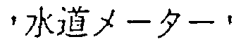 comprising black picture elements are input, and that a connected element R11, which is a part of the character
 , and the connected elements linked to the connected element R11 are extracted.
- In this case, as shown in FIG. 17B, the enclosing rectangle G1 of the connected element R11 is generated, and the vicinity B1 of the connected element is set around the enclosing rectangle G1. When the vicinity B1 of the connected element is set, the connected elements R12 through R20 partly or completely overlap the vicinity B1 of the connected element are extracted as shown in FIG. 17C. When the connected elements R12 through R20 are extracted, the familial similarity between the connected element R11 and the connected elements R12 through R20 is checked as shown in FIG. 17D. Since the connected element R12 is quite different from the connected element R11 in thickness, the connected element R12 is removed from targets to be linked to the connected element R11. As a result, the connected elements R13 through R20, that is, the connected elements excluding the connected element R12, are linked to the connected element R11.
- FIG. 18 shows examples of groups which can be or cannot be defined as cliques.
- In FIG. 18A, the characters
group 1. Since the black picture element area corresponding to the background against the white charactersgroup 2. - Since the black picture element areas corresponding to the background against the white characters
- Next, since the rectangular areas of the
groups 1 and b do not overlap each other as shown in FIG. 18C, thegroups 1 and b are considered to form a clique, and a consistent combination. Furthermore, since the rectangular areas of thegroups 1 and a overlap each other as shown in FIG. 18D, thegroups 1 and a are considered not to form a clique, and to be an inconsistent combination. - Thus, as shown in FIG. 18B, the
group 1 makes a consistent combination with the group b or thegroup 2, but does not make a consistent combination with the group a. Thegroup 2 makes a consistent combination with thegroup 1 or the group a, but does not make a consistent combination with the group b. The group a makes a consistent combination with thegroup 2 or the group b, but does not make a consistent combination with thegroup 1. The group b makes a consistent combination with thegroup 1 or the group a, but does not make a consistent combination with thegroup 2. - FIG. 19 shows the method of computing the evaluation value of the combination.
- In FIG. 19, the evaluation value of a combination is obtained by combining the evaluation values of groups, that is, the factors of the character recognition levels of groups and the areas of the rectangular areas of respective groups of consistent combinations.
- For example, assume that a combination of the groups A and B is obtained from the input image shown in FIG. 19 as a combination of consistent groups. Assuming that the area of the rectangular area of the group A is Sa, the character recognition level of a group is Ra, the area of the rectangular area of the group B is Sb, and the character recognition level of a group is Rb, the evaluation value of the combination of the groups A and B can be computed by the following equation.
- A monochrome image has been described above. However, the present invention is not limited to a monochrome image, but can be widely applied to color characters and backgrounds by replacing the monochrome picture elements with the chromaticity, the brightness, and the density.
- In the above description, vertically printed characters are exemplified. However, it is obvious that the present invention can be applied not only to vertically printed characters, but also vertically and horizontally printed characters.
- Described below is the pattern extraction apparatus according to an embodiment of the present invention.
- According to the embodiment of the present invention, the connected element overlap nest integrating process is omitted to avoid integrating the entire image. Additionally, a part of a drawing or a photograph which may cause an undesired influence when a headline area is extracted is absorbed and integrated into a larger rectangle to reduce the influence. Normally, a rectangle comprising a part of a drawing or a photograph often overlap another rectangle. This is a clue to retrieving these rectangles. Then, the overlap related to a headline rectangle is computed. It is determined that a value higher than a predetermined threshold indicates a rectangle formed by a part of a drawing or a photograph, and the rectangle is processed in the overlap nest integrating process.
- To estimate a correct text character size when the overlap nest integrating process is omitted, a histogram which relates to the size of an enclosing rectangle of a connected element, and is weighted by the frequency and the area of a rectangle is used. Thus, even if a part of a character is counted as is, and the number of rectangles smaller than an actual text character is the largest, it is not the largest number in a new histogram because of the weight of area. Therefore, the size of a rectangle smaller than an actual text character is not defined as the size of an estimated character. On the other hand, even if there is a large connected element, the frequency of the larger element is lower. Therefore, the size of a rectangle larger than an actual text character is not defined as an estimated character size.
- The embodiment of the present invention is described below by referring to an example of a binary monochrome image.
- FIG. 20 is a flowchart showing the operation of the pattern extraction apparatus according to the embodiment of the present invention.
- In FIG. 20, the labelling process is performed on an input image (step S51). The coordinate information about the enclosing rectangle of each connected element is obtained in the labelling process.
- Next, the size of a text character is estimated (step S52). In estimating the size of a text character, a histogram relating to the size of the enclosing rectangle of a connected element is generated. The histogram is weighted by the frequency and the area of a rectangle. Practically, assuming that the width and the height of a connected element are respectively dx and dy, the histogram of the larger is adopted. The following transformation is performed on each value H (i) of the obtained histogram to generate a new histogram H'.
- In this new histogram, the point indicating the maximum histogram value refers to the text character size.
- FIG. 21 shows an example of a histogram for obtaining the size of an enclosing rectangle according to an embodiment of the present invention.
- In FIG. 21A, when a histogram showing the frequency H of the size of an enclosing rectangle is generated without performing the overlap nest integrating process, the peak P2 corresponding to the size of a text character is generated, and the peak P1 corresponding to the size of the enclosing rectangle of a part of a character before integration can also be generated.
- Therefore, when the text character size is estimated using the histogram, the size of the enclosing rectangle corresponding to the peak P1 may be estimated as the text character size. Thus, the text character size may be mistakenly estimated.
- On the other hand, if the histogram shown in FIG. 21A is weighted by the size of the enclosing rectangle in FIG. 21B, the histogram value H of the peak P1 indicating a small enclosing rectangle is smaller than the histogram value H of the peak P2 indicating a large enclosing rectangle. As a result, using the histogram shown in FIG. 21B, it is possible to estimate the value of the peak P2' corresponding to the size of the text character to be larger than the value of the peak P1' corresponding to the size of the enclosing rectangle of a part of the character before integration. Thus, mistakenly estimating the size of the enclosing rectangle corresponding to the peak P1' as the text character size can be avoided. As a result, the text character size can be correctly estimated.
- Next, the projection table of text character rectangle candidates is generated (step S53).
- In generating the projection table, a text character rectangle candidate is selected from all rectangles. Practically, assuming that the width of a connected element is dx, the height of the connected element is dy, the size of the text character is c, and the threshold is α, a rectangle satisfying the following equation is defined as a candidate for a text character rectangle.
- Then, relating to the x and y coordinate axes of the entire image, a projection of a candidate for a text character rectangle is made. That is, when the number of the candidate for a text character rectangle is n, and the coordinates of the upper left point and the lower right point of the rectangle are respectively (x1, y1) and (x2, y2), the number n is stored in the range from x1 to x2 along the x coordinate axis and in the range from y1 to y2 along the y coordinate axis. Thus, a projection table for a candidate for a text character rectangle is generated.
- FIG. 22 shows an example of the method of projecting a rectangle number according to an embodiment of the present invention.
- In FIG. 22, assuming that the enclosing rectangles having the
rectangle numbers 1 through 6 are generated, each of therectangle numbers 1 through 6 is projected on the x and y coordinate axes. For example, at the points where the x coordinates are 4 through 6, the enclosing rectangles having therectangle numbers rectangle numbers rectangle number 6 is positioned. As a result, therectangle number 6 is projected on the x coordinates 7, 8, and 10. At the point where the x coordinate is 9, the enclosing rectangles having therectangle numbers 2. 4. and 6 are positioned. As a result, therectangle numbers rectangle numbers rectangle numbers - Then, a candidate for a headline rectangle is selected (step S54). In selecting a candidate for a headline rectangle, a headline and characters forming a headline are selected. Basically, a portion obtained by multiplying a size of a text character by a predetermined number is defined as a candidate for a headline rectangle.
- FIG. 23 is a flowchart showing the method of selecting a candidate for a headline rectangle according to an embodiment of the present invention.
- In FIG. 23, assume that the coordinates of the upper left point of the rectangle are (x1, y1), the coordinates of the lower right point of the rectangle are (x2, y2), the difference between the x coordinate x2 of the lower right point of the rectangle and the x coordinate x1 of the upper left point of the rectangle is dx, the difference between the y coordinate y2 of the lower right point of the rectangle and the y coordinate y1 of the upper left point of the rectangle is dy, and the text character size is moji (step S71).
- Next, it is determined whether or not the following conditions are satisfied (step S72). If the conditions are not satisfied, then it is determined that the portion being processed is not a candidate for a headline rectangle, thereby terminating the process. If the conditions are satisfied, then control is passed to step S73.
- Then, it is determined whether or not the following conditions, are satisfied (step S73). If the conditions are not satisfied, then it is determined that the portion being processed is not a candidate for a headline rectangle, thereby terminating the process. If the conditions are satisfied, then the portion being processed is entered as a candidate for a headline rectangle (step S74).
- Then, a box rectangle is checked (step S55).
- Assuming that the entire box, or the enclosing rectangle of a connected element forming part of the entire character box, is referred to as a box rectangle, the box rectangle cannot be a headline, and cannot be distinguished from a headline rectangle by size or shape. First, the box rectangle should be removed from all of the boxes. Normally, a character box contains a number of text characters, but a headline rectangle hardly contains text characters. Therefore, the number of candidates for text character boxes is counted in a rectangle to determine whether or not they are box rectangles. That is, the number of candidates for text character boxes in the enclosing rectangle is counted in a target area. If the number is larger than a predetermined value, then it is determined that the portion is an area enclosed by a box rectangle or a part of a box rectangle. A candidate for a text character box refers to an area of connected black picture elements enclosed by a rectangle of a text character size. The number of text characters in a character box can be efficiently computed using a projection table of candidates for character boxes.
- FIG. 24 shows a method of checking a box according to an embodiment of the present invention.
- In FIG. 24, it is assumed that enclosing rectangles K1 through K6 are extracted, and the enclosing rectangles K1 through K5 are selected as candidates for headline character boxes. Assume that the enclosing rectangles K1 through K4 enclose headline characters, and the enclosing rectangle K5 is a character box enclosing text characters. In this case, if the enclosing rectangles K1 through K5 are put in the same group, then a group of headline character enclosing rectangles include a rectangle enclosing non-headline characters. As a result, the headline characters cannot be correctly extracted, and therefore, it is necessary to remove the enclosing rectangle K5 from the candidates for headline character boxes.
- Then, assuming that a character box enclosing text characters contains a number of text characters, the number of enclosing rectangles K6 of the size of text characters contained in the enclosing rectangles K1 through K5 selected as candidates for headline character boxes is counted.
- As a result, since the enclosing rectangle K5 contains a number of the enclosing rectangles K6 of a text character size whereas the enclosing rectangles K1 through K4 do not contain an enclosing rectangle of a text character size, the enclosing rectangles K5 containing a number of the enclosing rectangles K6 of a text character size should be removed from the candidates for headline character boxes so that only the enclosing rectangles K1 through K4 can be correctly selected as candidates for headline character boxes.
- Performed next is the partially-overlapping nest integrating process (step S56).
- Candidates for headline character boxes may contain enclosing rectangles of connected elements comprising a part of a drawing or a photograph. These enclosing rectangles may be integrated into other correct headline rectangles, thereby causing an undesired influence. The undesired influence on the extraction of a headline rectangle should be reduced by absorbing or integrating the enclosing rectangle forming part of a drawing or a photograph into a larger rectangle. Normally, rectangles forming part of a drawing or a photograph often overlap each other, which is a clue to easily detecting the rectangles. Therefore, the overlap level of enclosing rectangles is computed. If the level exceeds a predetermined threshold, it is determined that the enclosing rectangle is obtained as a part of a drawing or a photograph. Then, the overlapping nest integrating process is performed only on the rectangle. The overlap level of an enclosing rectangle indicates how many other enclosing rectangles overlap the enclosing rectangle.
- FIG. 25 shows the overlapping nest integrating process.
- It is assumed that, when the connected elements of the characterare extracted as shown in FIG. 25, two connected elements R1 and R2 are extracted, and the enclosing rectangle K11 of the connected element R1 and the enclosing rectangle K12 of the connected element R2 are generated. When the overlapping nest integrating process is performed on the enclosing rectangles K11 and K12, the enclosing rectangle K13 encompassing the enclosing rectangles K11 and K12 is generated.
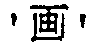
- As a result, when a different label is assigned to each stroke of a character comprising a plurality of strokes, the strokes forming a character can be put in one group.
- FIG. 26 shows the partially-overlapping nest integrating process.
- In FIG. 26A, enclosing rectangles K21 through K26 are generated. In this case, for example, the enclosing rectangle K22 overlaps two enclosing rectangles K21 and K23. Therefore, the overlap level of the enclosing
rectangle 22 is 2. Since the enclosingrectangle 23 overlaps four enclosing rectangles K22, and K24 through K26, the overlap level of the enclosingrectangle 23 is 4. - Assuming that the overlapping nest integrating process is performed only on the enclosing rectangles having the overlap level of 4 or higher, the enclosing
rectangle 27 containing the enclosing rectangles K22 through K26 is generated as shown in FIG. 26B, and the enclosing rectangles K21 and K27 are not integrated. - For example, if the enclosing rectangle K21 is a headline character box, the enclosing rectangles K22 through K26 enclose the background pattern, and the overlapping nest integrating process is performed without considering the overlap level, then all the enclosing rectangles K21 through K26 are integrated, the headline character boxes are lost, and the headline character area cannot be extracted.
- On the other hand, when the overlapping nest integrating process is not performed at all, the enclosing rectangles K21 through K26 separately exists, and the enclosing rectangles K22 through K26 of the background pattern against headline characters may be selected as candidates for headline rectangles. When the enclosing rectangles K22 through K26 of the background pattern against headline characters are selected as candidates for headline rectangles, headline characters cannot be correctly extracted.
- Then, the enclosing rectangles K21 through K26 to be processed in the overlapping nest integrating process are selected based on the overlap level, and the overlapping nest integrating process is performed only on the enclosing rectangles K22 through K26. As a result, the enclosing rectangles K22 through K26 of the background pattern against headline characters are absorbed in the enclosing rectangle K27, thereby preventing the enclosing rectangles K22 through K26 from being selected as candidates for headline rectangle. Furthermore, the enclosing rectangle K21 of the headline characters can be maintained as is, thereby improving the precision in extracting headline characters.
- The overlap level can be computed as described below.
- First, as shown in FIG. 22, a projection table of candidates for headline rectangles is generated by the method shown in FIG. 22. Then, the overlap level is computed for each picture element of a candidate for a headline rectangle by referring to a headline rectangle number based on the x coordinate axis projection table and the y coordinate axis projection table.
- Performed next is the rectangular integration (step S57).
- In integrating rectangles, headline rectangles are integrated. First, the vicinity area of a target headline rectangle is defined, and another headline rectangle a part of which is contained in the vicinity area is checked. Then, it is determined whether or not the target headline rectangle can be integrated into the headline rectangle in the vicinity area. At this time, the vicinity area is defined and the integration conditions are determined for both vertically and horizontally printed characters.
- FIG. 27 shows an example of a vicinal rectangle.
- In FIG. 27, assuming that the enclosing rectangles K31 through K36 are generated and a vicinity area is determined using the enclosing rectangle K31 as a target rectangle, the vicinity area H1 is set within a predetermined range of the enclosing rectangle K31. The enclosing rectangle K32 through K34 within the vicinity area H1 are selected as candidates for enclosing rectangles to be integrated into the enclosing rectangle K31. The enclosing rectangles K35 and K36 are removed from the candidates for the enclosing rectangles to be integrated into the enclosing rectangle K31.
- FIG. 28 is a flowchart showing the vicinity integrating process.
- First, in FIG. 27, a set of rectangles are input (step S81) to establish a link between rectangles (step S82). In establishing a link between rectangles, a target rectangle is set first (step S91), and an enclosing rectangle in the vicinity of the target rectangle is extracted, thereby determining the vicinal rectangle of the target rectangle (step S92). Thus, considering the relative position between the target rectangle and the vicinal rectangle, the thickness of a character line, the density of black picture elements in each rectangle, etc., the possibility of the integration of the target rectangle and the vicinal rectangle is determined. If it is determined that the target rectangle and the vicinal rectangle can be integrated, a link is established.
- Next, a set of very large linked rectangles are extracted (step S83). Rectangles belonging to the set of very large rectangles are deleted from the set of rectangles input in step S81, and an enclosing rectangle of the set of very large rectangles is added to the set of rectangles (step S84).
- Performed next is the overlapping rectangle removing process (step S58).
- In this overlapping rectangle removing process, one of overlapping rectangles is deleted to avoid double rectangles in the integrated headline rectangles.
- FIG. 29 shows an example of double rectangles .
- In FIG. 29, when the enclosing rectangles K41 and K42 are extracted, and vertical integration is performed using the enclosing rectangle K41 as a target rectangle, the vicinal area H11 is set around the enclosing rectangle K41. If the enclosing rectangle K42 in the vicinal area H11 is extracted, and it is determined that the enclosing rectangles K41 and K42 can be integrated, then the enclosing rectangle K43 including the enclosing rectangles K41 and K42 is generated.
- On the other hand, if horizontal integration is performed using the enclosing rectangle K41 as a target rectangle, then the vicinal area H12 is set around the enclosing rectangle K41. If the enclosing rectangle K42 in the vicinal area H12 is extracted, and it is determined that the enclosing rectangles K41 and K42 can be integrated, then the enclosing rectangle K43 including the enclosing rectangles K41 and K42 is generated.
- As a result, since the two same enclosing rectangles K43 are generated, one of the enclosing rectangle K43 is deleted.
- Then, a check is made on a box rectangle (step S59).
- In this box rectangle check, it is determined whether or not an obtained headline rectangle is a box rectangle using a projection table, and a box rectangle is removed from headline rectangles.
- Then, a headline rectangle is marked (step S60). In marking a headline rectangle, a mark is assigned to an obtained headline rectangle based on its size and shape.
- FIG. 30 shows the method of marking a headline rectangle.
- In FIG. 30, an enclosing rectangle K51 is generated. Assuming that the width and the length of the enclosing rectangle K51 is dx and dy respectively, the mark of the enclosing rectangle K51 is computed by the following equation.
- When a plurality of titles comprising headline characters are obtained from a document image by computing the mark, the titles can be assigned priority numbers for output.
- By means of the techniques as described above, since connected elements are grouped based on familial similarity, a character recognizing process is performed for each group to assign a character string level and extract a group of consistent combinations. Therefore, a character string can be extracted from a complicated image comprising a background pattern containing a combination of white and black portions, various types of fonts, a color document, a plurality of lines, a combination of vertical and horizontal character strings, and a compound of them.
- Since a color is not determined, a character string area is not assumed during an extracting process, or standard line width of a character is not determined in the extracting process, a character color is not mis-recognized or a relatively thin line cannot be missed, thereby improving the precision in extraction of a character string.
- A combination of portions, whose areas do not overlap each other based on the recognition results of the patterns obtained from an input image and its black/white inverse image, is defined as an extraction result of the pattern from the input image. In prior-proposed technology, when characters formed by black picture elements and white characters against the black background co-exist in a headline of newspapers, etc., the color of a character is determined by the number of black character candidates and white character candidates. Therefore, when it is determined that the character color is black, only the connected elements of the input image is to be processed thereafter and a black character can be correctly recognized, but a white character against the black background cannot be recognized. Similarly, when it is determined that the character color is white, only the connected elements of the black/white inverse image is to be processed for character recognition and a white character against the black background can be correctly recognized, but a black character cannot be recognized. By using the above technique, the above described mis-recognition can be avoided. Thus, a character string can be extracted with precision from a complicated image comprising a background pattern containing a combination of white and black portions, various types of fonts, a color document, a plurality of lines, a combination of vertical and horizontal character strings, and a compound of them.
- According to the present invention, the frequency of an enclosing rectangle is weighted by the area of the enclosing rectangle. Therefore, even if a character is formed by a plurality of separate strokes, not processed in the overlapping nest integrating process, and therefore an enclosing rectangle generated for each stroke remains as is, the enclosing rectangle formed by a part of one character is smaller than an enclosing rectangle formed for an entire character. As a result, the evaluation of the frequency of the enclosing rectangle formed by a part of one character can be set lower, and the influence of the size of a part of a character can be reduced in estimating the size of a character. Therefore, the character size can be estimated with high precision even when the overlapping nest integrating process is not performed.
- It may also be provided that the number of text characters in a character box is counted. Therefore, when headline characters are extracted from newspapers, etc., and when a rectangular character box enclosing text characters exists near the headline characters, only the box rectangle can be extracted, thereby distinguishing the rectangular character box from the enclosing rectangle for the headline characters. As a result, only the headline characters can be extracted with high precision.
- Also, a rectangle number assigned to an enclosing rectangle may be projected to each coordinate set on the input image. Therefore, an enclosing rectangle existing in another enclosing rectangle can be easily extracted. As a result, even if a rectangular character box enclosing text characters and headline characters coexist, only the box rectangle can be quickly extracted.
- Optionally, an overlapping nest integrating process is partially performed. Therefore, the overlapping nest integrating process is performed only on the enclosing rectangles having a high overlap level, and the process can be omitted on enclosing rectangles having a low overlap level. As a result, an enclosing rectangle of headline characters can be prevented from being lost by enclosing rectangles being integrated on the entire screen, and a part of a drawing or a photograph having a high overlap level can be absorbed or integrated into a larger rectangle. Thus, it can be avoided that an enclosing rectangle of a part of a drawing or a photograph remains as is to be mistakenly extracted as headline characters or mistakenly integrated into a rectangle as headline characters. As a result, headline characters can be extracted with high precision even if the headline characters coexist with a drawing, a photograph, etc.
- In another technique described above, a rectangle number assigned to an enclosing rectangle is projected to each coordinate set on the input image. Therefore, enclosing rectangles overlapping each other can be easily extracted, thereby quickly computing the overlap level of the enclosing rectangles.
- In the following claims, the term "color" also includes black and white.
said histogram generation means generates said histogram by weighting the frequency of each enclosing rectangle by the size of the enclosing rectangle.
Claims (7)
- A pattern extraction apparatus comprising:connected element extraction means (11) for extracting connected elements of an input image including characters;enclosing rectangle generation means (12) for generating an enclosing rectangle of the connected elements;histogram generation means for generating a histogram showing the frequency (H) of occurrence in the input image of enclosing rectangles of various sizes; andcharacter size estimation means for estimating a size of an enclosing rectangle indicating a maximum value of the histogram as the character size of the input image;
characterized in that
said histogram generation means generates said histogram by weighting the frequency (H) of each enclosing rectangle by the size of the enclosing rectangle. - The apparatus according to claim 1, applied to an input image including headline characters to be extracted and text characters, whereby the enclosing rectangles include at least one headline character box and at least one text character box, the apparatus further comprising:grouping means for selecting, from the enclosing rectangles, candidates (K1-K5) for headline character boxes;counting means for counting, in each of the enclosing rectangles which are candidates (K1-K5) for headline character boxes, the number of smaller enclosing rectangles (K6) of the size of text characters contained in the enclosing rectangle; andremoving means for removing, from the candidates (K1-K5) for headline character boxes, any enclosing rectangle (K5) containing a predetermined number or more of the smaller enclosing rectangles (K6).
- The apparatus according to claim 2, wherein each enclosing rectangle has a position defined by co-ordinates in x and y co-ordinate axes of the input image, and wherein the apparatus further comprises:projecting means for assigning a rectangle number (1...6) identifying each of the enclosed rectangles, andprojecting each of the rectangle numbers onto said x and y co-ordinate axes to form a projection table (Fig. 22) for candidates for a text character box in which each rectangle number is stored at the co-ordinates of the corresponding enclosing rectangle.
- A pattern extraction method comprising the steps of:extracting connected elements of an input image including characters;generating an enclosing rectangle of the connected elements;generating a histogram showing the frequency (H) of occurrence in the input image of enclosing rectangles of various sizes; andestimating a size of an enclosing rectangle indicating a maximum value of the histogram as the character size of the input image; characterized in that:said histogram generation step generates said histogram by weighting the frequency (H) of each enclosing rectangle by the size of the enclosing rectangle.
- The method.according to claim 4, applied to an input image including headline characters to be extracted, and text characters, whereby the enclosing rectangles include at least one headline character box and at least one text character box, the method further comprising:selecting, from the enclosing rectangles, candidates (K1 - K5) for headline character boxes;counting, in each of the enclosing rectangles which are candidates (K1 - K5) for headline character boxes, the number of smaller enclosing rectangles (K6) of the size of the text characters contained in the enclosing rectangle; andremoving from the candidates (K1 - K5) for headline character boxes, any enclosing rectangle (K5) containing a predetermined number or more of the smaller enclosing rectangles (K6).
- The method according to claim 5, wherein each enclosing rectangle has a position defined by co-ordinates in x and y co-ordinate axes of the input image, and wherein the method further comprises;
assigning a rectangle number (1...6) identifying each of the enclosed rectangles, and projecting each of the rectangle numbers onto said x and y co-ordinate axes to form a projection table (Fig. 22) for candidates for a text character box in which each rectangle number is stored at the co-ordinates of the corresponding enclosing rectangle. - A computer-readable storage medium storing a program causing a computer to execute a pattern extracting method comprising:wherein said histogram generation step generates said histogram by weighting the frequency (H) of each enclosing rectangle by the size of the enclosing rectangle.extracting connected elements of an input image including characters;generating an enclosing rectangle of the connected elements;generating a histogram showing the frequency (H) of occurrence in the input image of enclosing rectangles of various sizes; andestimating a size of an enclosing rectangle indicating a maximum value of the histogram as the character size of the input image;
Applications Claiming Priority (5)
| Application Number | Priority Date | Filing Date | Title |
|---|---|---|---|
| JP35135397 | 1997-12-19 | ||
| JP35135397 | 1997-12-19 | ||
| JP14619998A JP3601658B2 (en) | 1997-12-19 | 1998-05-27 | Character string extraction device and pattern extraction device |
| JP14619998 | 1998-05-27 | ||
| EP98309724A EP0924639B1 (en) | 1997-12-19 | 1998-11-26 | Character string extraction apparatus and pattern extraction apparatus |
Related Parent Applications (1)
| Application Number | Title | Priority Date | Filing Date |
|---|---|---|---|
| EP98309724A Division EP0924639B1 (en) | 1997-12-19 | 1998-11-26 | Character string extraction apparatus and pattern extraction apparatus |
Publications (2)
| Publication Number | Publication Date |
|---|---|
| EP1265188A1 EP1265188A1 (en) | 2002-12-11 |
| EP1265188B1 true EP1265188B1 (en) | 2004-10-13 |
Family
ID=26477082
Family Applications (4)
| Application Number | Title | Priority Date | Filing Date |
|---|---|---|---|
| EP02019039A Expired - Lifetime EP1265187B1 (en) | 1997-12-19 | 1998-11-26 | Pattern extraction apparatus and method |
| EP02019041A Expired - Lifetime EP1265189B1 (en) | 1997-12-19 | 1998-11-26 | Pattern extraction apparatus and method |
| EP02019040A Expired - Lifetime EP1265188B1 (en) | 1997-12-19 | 1998-11-26 | Pattern extraction apparatus and method |
| EP98309724A Expired - Lifetime EP0924639B1 (en) | 1997-12-19 | 1998-11-26 | Character string extraction apparatus and pattern extraction apparatus |
Family Applications Before (2)
| Application Number | Title | Priority Date | Filing Date |
|---|---|---|---|
| EP02019039A Expired - Lifetime EP1265187B1 (en) | 1997-12-19 | 1998-11-26 | Pattern extraction apparatus and method |
| EP02019041A Expired - Lifetime EP1265189B1 (en) | 1997-12-19 | 1998-11-26 | Pattern extraction apparatus and method |
Family Applications After (1)
| Application Number | Title | Priority Date | Filing Date |
|---|---|---|---|
| EP98309724A Expired - Lifetime EP0924639B1 (en) | 1997-12-19 | 1998-11-26 | Character string extraction apparatus and pattern extraction apparatus |
Country Status (6)
| Country | Link |
|---|---|
| US (1) | US6563949B1 (en) |
| EP (4) | EP1265187B1 (en) |
| JP (1) | JP3601658B2 (en) |
| KR (2) | KR100325384B1 (en) |
| CN (1) | CN1119767C (en) |
| DE (3) | DE69827048D1 (en) |
Families Citing this family (31)
| Publication number | Priority date | Publication date | Assignee | Title |
|---|---|---|---|---|
| JP2001060247A (en) * | 1999-06-14 | 2001-03-06 | Fuji Xerox Co Ltd | Device and method for image processing |
| JP2001052116A (en) * | 1999-08-06 | 2001-02-23 | Toshiba Corp | Device and method for matching pattern stream, device and method for matching character string |
| JP3604993B2 (en) * | 2000-03-16 | 2004-12-22 | シャープ株式会社 | Image encoding device, image encoding method, image decoding device, and image decoding method |
| JP4047090B2 (en) * | 2002-07-31 | 2008-02-13 | キヤノン株式会社 | Image processing method and image processing apparatus |
| JP2004348706A (en) | 2003-04-30 | 2004-12-09 | Canon Inc | Information processing device, information processing method, storage medium, and program |
| US7171618B2 (en) * | 2003-07-30 | 2007-01-30 | Xerox Corporation | Multi-versioned documents and method for creation and use thereof |
| US7035438B2 (en) * | 2003-07-30 | 2006-04-25 | Xerox Corporation | System and method for measuring and quantizing document quality |
| US7483570B1 (en) * | 2004-02-11 | 2009-01-27 | Knight Andrew F | Software and method for creating a dynamic handwriting font |
| JP4774200B2 (en) * | 2004-04-21 | 2011-09-14 | オムロン株式会社 | Character string area extractor |
| US20050254546A1 (en) * | 2004-05-12 | 2005-11-17 | General Electric Company | System and method for segmenting crowded environments into individual objects |
| EP1785847B1 (en) * | 2005-10-27 | 2015-11-18 | Accenture Global Services Limited | Display apparatus for automatically visualizing an application landscape |
| US7561722B2 (en) * | 2005-12-14 | 2009-07-14 | Xerox Corporation | System and method for interactive document layout |
| JP4807618B2 (en) * | 2006-03-06 | 2011-11-02 | 富士ゼロックス株式会社 | Image processing apparatus and image processing program |
| JP4907382B2 (en) * | 2007-02-23 | 2012-03-28 | ジーイー・メディカル・システムズ・グローバル・テクノロジー・カンパニー・エルエルシー | Ultrasonic image display method and ultrasonic diagnostic apparatus |
| US8068684B2 (en) * | 2007-05-04 | 2011-11-29 | I.R.I.S. | Compression of digital images of scanned documents |
| US8094202B2 (en) * | 2007-05-17 | 2012-01-10 | Canon Kabushiki Kaisha | Moving image capture apparatus and moving image capture method |
| JPWO2009081791A1 (en) * | 2007-12-21 | 2011-05-06 | 日本電気株式会社 | Information processing system, method and program thereof |
| US8131758B2 (en) | 2007-12-26 | 2012-03-06 | Novell, Inc. | Techniques for recognizing multiple patterns within a string |
| CN101551859B (en) * | 2008-03-31 | 2012-01-04 | 夏普株式会社 | Image recognition device and image retrieval device |
| US8134194B2 (en) * | 2008-05-22 | 2012-03-13 | Micron Technology, Inc. | Memory cells, memory cell constructions, and memory cell programming methods |
| US8037410B2 (en) * | 2008-10-27 | 2011-10-11 | Yahoo! Inc. | Method and apparatus for estimating the size of rendered text |
| US8824785B2 (en) * | 2010-01-27 | 2014-09-02 | Dst Technologies, Inc. | Segregation of handwritten information from typographic information on a document |
| JP5673033B2 (en) * | 2010-11-30 | 2015-02-18 | 富士ゼロックス株式会社 | Image processing apparatus and image processing program |
| JP5672059B2 (en) * | 2011-02-24 | 2015-02-18 | 富士通株式会社 | Character recognition processing apparatus and method, and character recognition processing program |
| JP5691817B2 (en) * | 2011-05-12 | 2015-04-01 | 富士ゼロックス株式会社 | Information processing apparatus and information processing program |
| JP5831420B2 (en) * | 2012-09-28 | 2015-12-09 | オムロン株式会社 | Image processing apparatus and image processing method |
| JP6003705B2 (en) * | 2013-02-14 | 2016-10-05 | 富士ゼロックス株式会社 | Information processing apparatus and information processing program |
| JP2015040908A (en) * | 2013-08-20 | 2015-03-02 | 株式会社リコー | Information processing apparatus, information update program, and information update method |
| JP6303671B2 (en) * | 2014-03-20 | 2018-04-04 | 富士ゼロックス株式会社 | Image processing apparatus and image processing program |
| CN106157250B (en) * | 2015-03-26 | 2019-03-01 | 富士通株式会社 | The method and apparatus for removing the marking in file and picture |
| WO2018189802A1 (en) | 2017-04-11 | 2018-10-18 | 楽天株式会社 | Image processing device, image processing method, and program |
Family Cites Families (13)
| Publication number | Priority date | Publication date | Assignee | Title |
|---|---|---|---|---|
| CH591726A5 (en) * | 1973-07-30 | 1977-09-30 | Nederlanden Staat | |
| DE68928703T2 (en) * | 1988-07-20 | 1998-12-10 | Fujitsu Ltd | LETTER RECOGNITION DEVICE |
| US5048109A (en) | 1989-12-08 | 1991-09-10 | Xerox Corporation | Detection of highlighted regions |
| JPH0528317A (en) * | 1991-07-23 | 1993-02-05 | Canon Inc | Method and device for processing image |
| JP3278471B2 (en) | 1991-11-29 | 2002-04-30 | 株式会社リコー | Area division method |
| US5680479A (en) | 1992-04-24 | 1997-10-21 | Canon Kabushiki Kaisha | Method and apparatus for character recognition |
| US5991435A (en) * | 1992-06-30 | 1999-11-23 | Matsushita Electric Industrial Co., Ltd. | Inspecting apparatus of mounting state of component or printing state of cream solder in mounting line of electronic component |
| JP2933801B2 (en) * | 1993-06-11 | 1999-08-16 | 富士通株式会社 | Method and apparatus for cutting out characters |
| JPH08123901A (en) | 1994-10-26 | 1996-05-17 | Nec Corp | Character extraction device and character recognition device using this device |
| JPH08194780A (en) | 1994-11-18 | 1996-07-30 | Ricoh Co Ltd | Feature extracting method |
| JP3400151B2 (en) * | 1994-12-08 | 2003-04-28 | 株式会社東芝 | Character string region extraction apparatus and method |
| KR19990014883A (en) * | 1996-03-18 | 1999-02-25 | 구니토모 시게 | Ultrasonic Diagnostic Device |
| US5892843A (en) * | 1997-01-21 | 1999-04-06 | Matsushita Electric Industrial Co., Ltd. | Title, caption and photo extraction from scanned document images |
-
1998
- 1998-05-27 JP JP14619998A patent/JP3601658B2/en not_active Expired - Fee Related
- 1998-11-24 US US09/198,460 patent/US6563949B1/en not_active Expired - Fee Related
- 1998-11-26 DE DE1998627048 patent/DE69827048D1/en not_active Expired - Fee Related
- 1998-11-26 EP EP02019039A patent/EP1265187B1/en not_active Expired - Lifetime
- 1998-11-26 EP EP02019041A patent/EP1265189B1/en not_active Expired - Lifetime
- 1998-11-26 EP EP02019040A patent/EP1265188B1/en not_active Expired - Lifetime
- 1998-11-26 DE DE69822237T patent/DE69822237D1/en not_active Expired - Lifetime
- 1998-11-26 DE DE69821595T patent/DE69821595D1/en not_active Expired - Lifetime
- 1998-11-26 EP EP98309724A patent/EP0924639B1/en not_active Expired - Lifetime
- 1998-12-05 KR KR1019980053284A patent/KR100325384B1/en not_active IP Right Cessation
- 1998-12-18 CN CN98125365A patent/CN1119767C/en not_active Expired - Fee Related
-
2001
- 2001-10-08 KR KR10-2001-0061753A patent/KR100383372B1/en not_active IP Right Cessation
Also Published As
| Publication number | Publication date |
|---|---|
| EP1265187A1 (en) | 2002-12-11 |
| EP0924639A2 (en) | 1999-06-23 |
| EP0924639B1 (en) | 2004-02-11 |
| JP3601658B2 (en) | 2004-12-15 |
| US6563949B1 (en) | 2003-05-13 |
| CN1119767C (en) | 2003-08-27 |
| KR19990062829A (en) | 1999-07-26 |
| DE69827048D1 (en) | 2004-11-18 |
| CN1220434A (en) | 1999-06-23 |
| EP1265187B1 (en) | 2004-03-03 |
| KR20010110369A (en) | 2001-12-13 |
| JPH11238098A (en) | 1999-08-31 |
| DE69822237D1 (en) | 2004-04-08 |
| KR100383372B1 (en) | 2003-05-12 |
| EP1265189A1 (en) | 2002-12-11 |
| EP0924639A3 (en) | 2001-11-28 |
| EP1265189B1 (en) | 2005-01-26 |
| DE69821595D1 (en) | 2004-03-18 |
| EP1265188A1 (en) | 2002-12-11 |
| KR100325384B1 (en) | 2002-04-17 |
Similar Documents
| Publication | Publication Date | Title |
|---|---|---|
| EP1265188B1 (en) | Pattern extraction apparatus and method | |
| JP3904840B2 (en) | Ruled line extraction device for extracting ruled lines from multi-valued images | |
| US4903311A (en) | Character region extracting method and apparatus capable of implementing the method | |
| US7751648B2 (en) | Image processing apparatus, image processing method, and computer program | |
| US8086040B2 (en) | Text representation method and apparatus | |
| CN109784342A (en) | A kind of OCR recognition methods and terminal based on deep learning model | |
| JP3913985B2 (en) | Character string extraction apparatus and method based on basic components in document image | |
| EP1300779A2 (en) | Form recognition system, form recognition method, program and storage medium | |
| JP2002042143A (en) | Frame recognition device and recording medium | |
| JP4077919B2 (en) | Image processing method and apparatus and storage medium therefor | |
| US10586125B2 (en) | Line removal method, apparatus, and computer-readable medium | |
| CN110210467B (en) | Formula positioning method of text image, image processing device and storage medium | |
| KR101660476B1 (en) | Metod for recognizing payment information in printed credit card | |
| US8295602B2 (en) | Image processing apparatus and image processing method | |
| JP2004030696A (en) | Character string extraction apparatus and pattern extraction apparatus | |
| US20220343666A1 (en) | Image processing apparatus, image processing method, and storage medium | |
| US11948342B2 (en) | Image processing apparatus, image processing method, and non-transitory storage medium for determining extraction target pixel | |
| JP2009272714A (en) | Image processing apparatus, image processing method, program, and recording medium with the program stored | |
| JP4271428B2 (en) | Character recognition method and character recognition apparatus | |
| JP2002015323A (en) | Document image layout distinguishing method and device thereof | |
| JP4136913B2 (en) | Form recognition device and form recognition method | |
| JP2001143076A (en) | Image processor | |
| CN115131806A (en) | Method and system for recognizing OCR (optical character recognition) image information of various certificates based on deep learning | |
| JPH0443476A (en) | Character recognizing device | |
| JPH0573714A (en) | Character recognition device |
Legal Events
| Date | Code | Title | Description |
|---|---|---|---|
| PUAI | Public reference made under article 153(3) epc to a published international application that has entered the european phase |
Free format text: ORIGINAL CODE: 0009012 |
|
| AC | Divisional application: reference to earlier application |
Ref document number: 924639 Country of ref document: EP |
|
| AK | Designated contracting states |
Kind code of ref document: A1 Designated state(s): AT BE CH CY DE DK ES FI FR GB GR IE IT LI LU MC NL PT SE |
|
| AX | Request for extension of the european patent |
Free format text: AL;LT;LV;MK;RO;SI |
|
| 17P | Request for examination filed |
Effective date: 20030107 |
|
| 17Q | First examination report despatched |
Effective date: 20030606 |
|
| AKX | Designation fees paid |
Designated state(s): DE FR GB |
|
| GRAP | Despatch of communication of intention to grant a patent |
Free format text: ORIGINAL CODE: EPIDOSNIGR1 |
|
| GRAS | Grant fee paid |
Free format text: ORIGINAL CODE: EPIDOSNIGR3 |
|
| GRAA | (expected) grant |
Free format text: ORIGINAL CODE: 0009210 |
|
| AC | Divisional application: reference to earlier application |
Ref document number: 0924639 Country of ref document: EP Kind code of ref document: P |
|
| AK | Designated contracting states |
Kind code of ref document: B1 Designated state(s): DE FR GB |
|
| PG25 | Lapsed in a contracting state [announced via postgrant information from national office to epo] |
Ref country code: FR Free format text: LAPSE BECAUSE OF FAILURE TO SUBMIT A TRANSLATION OF THE DESCRIPTION OR TO PAY THE FEE WITHIN THE PRESCRIBED TIME-LIMIT Effective date: 20041013 |
|
| REG | Reference to a national code |
Ref country code: GB Ref legal event code: FG4D |
|
| REG | Reference to a national code |
Ref country code: IE Ref legal event code: FG4D |
|
| REF | Corresponds to: |
Ref document number: 69827048 Country of ref document: DE Date of ref document: 20041118 Kind code of ref document: P |
|
| PG25 | Lapsed in a contracting state [announced via postgrant information from national office to epo] |
Ref country code: DE Free format text: LAPSE BECAUSE OF NON-PAYMENT OF DUE FEES Effective date: 20050601 |
|
| PLBE | No opposition filed within time limit |
Free format text: ORIGINAL CODE: 0009261 |
|
| STAA | Information on the status of an ep patent application or granted ep patent |
Free format text: STATUS: NO OPPOSITION FILED WITHIN TIME LIMIT |
|
| 26N | No opposition filed |
Effective date: 20050714 |
|
| EN | Fr: translation not filed | ||
| PGFP | Annual fee paid to national office [announced via postgrant information from national office to epo] |
Ref country code: GB Payment date: 20131120 Year of fee payment: 16 |
|
| GBPC | Gb: european patent ceased through non-payment of renewal fee |
Effective date: 20141126 |
|
| PG25 | Lapsed in a contracting state [announced via postgrant information from national office to epo] |
Ref country code: GB Free format text: LAPSE BECAUSE OF NON-PAYMENT OF DUE FEES Effective date: 20141126 |