EP1265116A2 - Image forming apparatus - Google Patents
Image forming apparatus Download PDFInfo
- Publication number
- EP1265116A2 EP1265116A2 EP02012398A EP02012398A EP1265116A2 EP 1265116 A2 EP1265116 A2 EP 1265116A2 EP 02012398 A EP02012398 A EP 02012398A EP 02012398 A EP02012398 A EP 02012398A EP 1265116 A2 EP1265116 A2 EP 1265116A2
- Authority
- EP
- European Patent Office
- Prior art keywords
- conveying means
- toner conveying
- toner
- recycle
- waste toner
- Prior art date
- Legal status (The legal status is an assumption and is not a legal conclusion. Google has not performed a legal analysis and makes no representation as to the accuracy of the status listed.)
- Granted
Links
Images
Classifications
-
- G—PHYSICS
- G03—PHOTOGRAPHY; CINEMATOGRAPHY; ANALOGOUS TECHNIQUES USING WAVES OTHER THAN OPTICAL WAVES; ELECTROGRAPHY; HOLOGRAPHY
- G03G—ELECTROGRAPHY; ELECTROPHOTOGRAPHY; MAGNETOGRAPHY
- G03G15/00—Apparatus for electrographic processes using a charge pattern
- G03G15/01—Apparatus for electrographic processes using a charge pattern for producing multicoloured copies
- G03G15/0105—Details of unit
-
- G—PHYSICS
- G03—PHOTOGRAPHY; CINEMATOGRAPHY; ANALOGOUS TECHNIQUES USING WAVES OTHER THAN OPTICAL WAVES; ELECTROGRAPHY; HOLOGRAPHY
- G03G—ELECTROGRAPHY; ELECTROPHOTOGRAPHY; MAGNETOGRAPHY
- G03G21/00—Arrangements not provided for by groups G03G13/00 - G03G19/00, e.g. cleaning, elimination of residual charge
- G03G21/10—Collecting or recycling waste developer
- G03G21/105—Arrangements for conveying toner waste
-
- G—PHYSICS
- G03—PHOTOGRAPHY; CINEMATOGRAPHY; ANALOGOUS TECHNIQUES USING WAVES OTHER THAN OPTICAL WAVES; ELECTROGRAPHY; HOLOGRAPHY
- G03G—ELECTROGRAPHY; ELECTROPHOTOGRAPHY; MAGNETOGRAPHY
- G03G2215/00—Apparatus for electrophotographic processes
- G03G2215/01—Apparatus for electrophotographic processes for producing multicoloured copies
- G03G2215/0103—Plural electrographic recording members
- G03G2215/0119—Linear arrangement adjacent plural transfer points
Definitions
- a problem with a full-color image forming apparatus which uses yellow toner, magenta toner, cyan toner and black toner, is that the toners of different colors are mixed in cleaning units. When more than preselected amounts of toners of different colors are mixed, the tones of colors vary. Further, the toners each having a particular charging characteristic are selectively scattered around. Image quality is therefore degraded unless only toners with low degrees of color mixture are recycled.
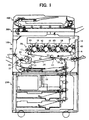
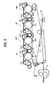
- a Y (yellow), an M (magenta), a C (cyan) and a Bk (black) image forming unit 18 are arranged side by side above part of the belt 10 extending between the support roller or first support roller 14 and the second support roller 15.
- the Y, M, C and Bk image forming units 18 are sequentially arranged in this order from the upstream side toward the downstream side in the direction of movement of the belt 10, constituting a tandem image forming mechanism 20.
- An optical writing unit 21 is positioned above the tandem image forming mechanism 20.
- the secondary image transferring device 22 additionally has a function of conveying the sheet carrying the image thereon to the fixing unit 25.
- a sheet reversing device 28 is arranged below the secondary image transferring device 22 and fixing unit 25 in parallel with the tandem image forming mechanism 20. In a duplex copy mode, the sheet reversing device 28 reverses the sheet for allowing images to be formed on both sides of the sheet.
- a drive motor causes one of the support rollers 14 through 16 to rotate while the other support rollers follow the rotation of the one support roller via the belt 10.
- photoconductive drums (simply drums hereinafter) 40 are rotated to form a Y, an M, a C and a Bk toner image thereon.
- the Y toner image through Bk toner image are sequentially transferred from the drums 40 to the belt 10 one above the other, completing a full-color image on the belt 10.
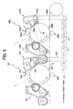
- the cleaning device 63 included in each of the Y, M and C image forming units 18 includes a screw 79 for toner collection.
- a vertical portion 90 forming part of a waste toner piping is communicated at one end to the rear end of the screw 79, as seen in a direction perpendicular to the sheet surface of FIG. 3, and connected at the other end to a horizontal portion 91 forming the other part of the waste toner piping.
- Toner collected by the screw 79 drops into the horizontal portion 91 of the piping via the vertical portion 90 due to gravity.
- a screw conveyor 92 is disposed in the horizontal portion 91 and conveys the above toner to a waste toner tank not shown.
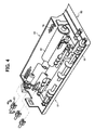
- the front end of the screw 79 as viewed in the direction perpendicular to the sheet surface of FIG. 3, is communicated to a recycling device 80 (see FIG. 4).
- FIG. 4 shows the Bk image forming unit in detail.
- the rotation of a cleaning drive shaft is transferred to the screw 79 via a coupling 93, causing the screw 79 to rotate.
- the cleaning drive shaft is controlled to selectively rotate in a forward direction or a reverse direction. Therefore, the screw 79 driven by the cleaning drive shaft selectively conveys the toner in the cleaning device 63 toward either one of the front end and rear end.
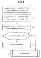
- FIG. 6 is a flowchart demonstrating, on the assumption that black is the last color, how recycle toner conveying means and waste toner conveying means assigned to the Bk image forming unit 18Bk are selectively operated.
- a decision is made on the number of pixels written over five consecutive times of image formation, i.e., the "n - 4" image formation to the "n" image formation at each image forming station.
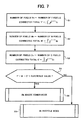
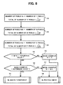
- FIG. 8 shows another modification of the procedure described with reference to FIG. 6 that sets a preselected delay at the time of transition form the waste toner mode to the recycle toner mode. As shown, even after the amounts of toners of the other colors to enter the Bk station have decreased, as determined on the basis of the numbers of pixels, the transition from the waste toner mode to the recycle toner mode is not effected until a preselected number of image forming cycles end in consideration of the influence of color mixture on the toner to be recycled.
Landscapes
- Physics & Mathematics (AREA)
- General Physics & Mathematics (AREA)
- Life Sciences & Earth Sciences (AREA)
- Engineering & Computer Science (AREA)
- Environmental & Geological Engineering (AREA)
- Sustainable Development (AREA)
- Cleaning In Electrography (AREA)
- Color Electrophotography (AREA)
- Control Or Security For Electrophotography (AREA)
- Dry Development In Electrophotography (AREA)
Abstract
Description
Claims (15)
- An image forming apparatus comprising:recycle toner conveying means for returning toner collected in a cleaning step to a developing device as recycled toner;waste toner conveying means for conveying the toner collected to a waste toner container as waste toner; andswitching means for selecting either one of said recycle toner conveying means and said waste toner conveying means.
- The apparatus as claimed in claim 1, wherein said switching means comprises a screw extending between said recycle toner conveying means and said waste toner conveying means and rotatable in opposite directions for conveying the toner collected to either one of said recycle toner conveying means and said waste toner conveying means.
- The apparatus as claimed in claim 1, further comprising a plurality of image forming units each being assigned to a particular color, wherein said switching means selects said recycle toner conveying means or said waste toner conveying means by determining, based on a number of pixels written in another color, whether or not the toner should be recycled.
- The apparatus as claimed in claim 3, wherein said switching means selects said recycle toner conveying means or said waste toner conveying means in accordance with a total number of pixels written over a preselected number of times of image formation.
- The apparatus as claimed in claim 3, wherein said switching means selects said recycle toner conveying means or said waste toner conveying means in accordance with a total of values produced by multiplying the numbers of pixels by correction coefficients.
- The apparatus as claimed in claim 3, wherein after a decision on selection, actual switchover between said recycle toner conveying means and said waste toner conveying means is effected after a preselected number of times of image formation or on the elapse of a preselected duration of rotation.
- The apparatus as claimed in claim 6, wherein the preselected number of times of image formation or the preselected duration of rotation is variable in accordance with a total of the numbers of pixels written over a preselected number of times of image formation.
- The apparatus as claimed in claim 6, wherein the preselected number of times of image formation or the preselected duration of rotation is variable in accordance with a total of values produced by multiplying the numbers of pixels by correction coefficients.
- The apparatus as claimed in claim 1, further comprising a plurality of image forming units each being assigned to a particular color, wherein said switching means selects either one of said recycle toner conveying means and said waste toner conveying means in accordance with a number of pixels written in a color upstream of a color which is a subject of decision as to whether or not to recycle.
- The apparatus as claimed in claim 9, wherein said switching means selects said recycle toner conveying means or said waste toner conveying means in accordance with a total number of pixels written over a preselected number of times of image formation.
- The apparatus as claimed in claim 9, wherein said switching means selects said recycle toner conveying means or said waste toner conveying means in accordance with a total of values produced by multiplying the numbers of pixels by correction coefficients.
- The apparatus as claimed in claim 9, wherein after a decision on selection, actual switchover between said recycle toner conveying means and said waste toner conveying means is effected after a preselected number of times of image formation or on the elapse of a preselected duration of rotation.
- The apparatus as claimed in claim 12, wherein the preselected number of times of image formation or the preselected duration of rotation is variable in accordance with a total of the numbers of pixels written over a preselected number of times of image formation.
- The apparatus as claimed in claim 12, wherein the preselected number of times of image formation or the preselected duration of rotation is variable in accordance with a total of values produced by multiplying the numbers of pixels by correction coefficients.
- The apparatus as claimed in claim 1, further comprising a plurality of image forming units each being assigned to a particularly color, wherein an image forming unit assigned to black is positioned at a most downstream side.
Applications Claiming Priority (2)
| Application Number | Priority Date | Filing Date | Title |
|---|---|---|---|
| JP2001172071A JP2002365995A (en) | 2001-06-07 | 2001-06-07 | Image forming device |
| JP2001172071 | 2001-06-07 |
Publications (3)
| Publication Number | Publication Date |
|---|---|
| EP1265116A2 true EP1265116A2 (en) | 2002-12-11 |
| EP1265116A3 EP1265116A3 (en) | 2003-03-12 |
| EP1265116B1 EP1265116B1 (en) | 2006-02-01 |
Family
ID=19013752
Family Applications (1)
| Application Number | Title | Priority Date | Filing Date |
|---|---|---|---|
| EP02012398A Expired - Lifetime EP1265116B1 (en) | 2001-06-07 | 2002-06-07 | Image forming apparatus with a recycled and waste toner conveying means |
Country Status (4)
| Country | Link |
|---|---|
| US (1) | US6782234B2 (en) |
| EP (1) | EP1265116B1 (en) |
| JP (1) | JP2002365995A (en) |
| DE (1) | DE60208949T2 (en) |
Cited By (5)
| Publication number | Priority date | Publication date | Assignee | Title |
|---|---|---|---|---|
| CN100412714C (en) * | 2005-03-25 | 2008-08-20 | 富士施乐株式会社 | image forming device |
| EP2157484A2 (en) | 2008-08-18 | 2010-02-24 | Ricoh Company, Ltd. | Image forming apparatus |
| CN102339006A (en) * | 2010-07-23 | 2012-02-01 | 增城市博大塑料五金有限公司 | Recovery method and recovery device for waste carbon powder, and regenerated plastic thereof |
| US8131178B2 (en) | 2009-05-14 | 2012-03-06 | Hewlett-Packard Development Company, L.P. | Image forming system cleaning station with waste toner collection |
| EP3264196A4 (en) * | 2015-02-27 | 2018-09-12 | C/o Canon Kabushiki Kaisha | Cartridge |
Families Citing this family (11)
| Publication number | Priority date | Publication date | Assignee | Title |
|---|---|---|---|---|
| JP4205531B2 (en) * | 2003-08-25 | 2009-01-07 | 株式会社リコー | Conveying apparatus and image forming apparatus |
| EP1589384B1 (en) * | 2004-04-23 | 2020-01-08 | Ricoh Company, Ltd. | Developer container |
| JP3944197B2 (en) * | 2004-07-01 | 2007-07-11 | キヤノン株式会社 | Image forming apparatus |
| JP4550501B2 (en) * | 2004-07-15 | 2010-09-22 | 株式会社リコー | Image forming apparatus |
| JP2007052051A (en) * | 2005-08-15 | 2007-03-01 | Ricoh Co Ltd | Image forming apparatus and conveyance driving method for recycling path of image forming apparatus |
| JP4966040B2 (en) * | 2007-02-02 | 2012-07-04 | キヤノン株式会社 | Residual toner recovery device for image forming apparatus |
| JP2009015097A (en) * | 2007-07-06 | 2009-01-22 | Ricoh Co Ltd | Image forming apparatus |
| JP5321965B2 (en) | 2008-09-11 | 2013-10-23 | 株式会社リコー | Image forming apparatus |
| JP2011022534A (en) * | 2009-07-21 | 2011-02-03 | Fuji Xerox Co Ltd | Cleaning device, image holder device and image forming apparatus |
| JP5424106B2 (en) | 2009-09-10 | 2014-02-26 | 株式会社リコー | Image forming apparatus |
| JP6163885B2 (en) * | 2013-05-31 | 2017-07-19 | ブラザー工業株式会社 | Image forming apparatus |
Family Cites Families (16)
| Publication number | Priority date | Publication date | Assignee | Title |
|---|---|---|---|---|
| JPS58158675A (en) * | 1982-03-15 | 1983-09-20 | Ricoh Co Ltd | Toner recovery device |
| JPH05241489A (en) * | 1992-02-28 | 1993-09-21 | Hitachi Koki Co Ltd | Toner recycling mechanism for electrophotographic devices |
| JP2857550B2 (en) * | 1992-11-16 | 1999-02-17 | 株式会社日立製作所 | Color electrophotographic equipment |
| US5442430A (en) * | 1993-06-16 | 1995-08-15 | Ricoh Company, Ltd. | Color image forming apparatus and cleaning device therefor |
| JP3365698B2 (en) | 1995-04-11 | 2003-01-14 | 株式会社リコー | Toner collection device |
| JP3533016B2 (en) * | 1995-05-30 | 2004-05-31 | 株式会社リコー | Electrophotographic equipment |
| JPH096202A (en) * | 1995-06-23 | 1997-01-10 | Ricoh Co Ltd | Multicolor electrophotographic toner recovery device |
| JPH0980858A (en) * | 1995-09-07 | 1997-03-28 | Ricoh Co Ltd | Image forming device |
| JP3204076B2 (en) * | 1996-03-29 | 2001-09-04 | 松下電器産業株式会社 | Electrophotographic copying machine |
| US6112046A (en) * | 1997-06-20 | 2000-08-29 | Ricoh Company, Ltd. | Image forming apparatus having recycling of residual toner |
| JP3794526B2 (en) | 1998-08-25 | 2006-07-05 | コニカミノルタビジネステクノロジーズ株式会社 | Image forming apparatus and control method thereof |
| US6167211A (en) * | 1998-08-25 | 2000-12-26 | Minolta Co., Ltd. | Image forming apparatus having a function for recycling collected toner and control method thereof |
| JP3807531B2 (en) | 1998-09-11 | 2006-08-09 | コニカミノルタビジネステクノロジーズ株式会社 | Image forming apparatus |
| JP3902355B2 (en) * | 1999-06-18 | 2007-04-04 | 株式会社リコー | Color image forming apparatus |
| JP2002023459A (en) * | 2000-07-06 | 2002-01-23 | Fujitsu Ltd | Color image forming equipment |
| US6611672B2 (en) * | 2000-09-26 | 2003-08-26 | Ricoh Company, Ltd. | Image forming apparatus, monocolor image forming apparatus, toner recycling apparatus and intermediate transfer member |
-
2001
- 2001-06-07 JP JP2001172071A patent/JP2002365995A/en active Pending
-
2002
- 2002-06-07 EP EP02012398A patent/EP1265116B1/en not_active Expired - Lifetime
- 2002-06-07 US US10/163,528 patent/US6782234B2/en not_active Expired - Fee Related
- 2002-06-07 DE DE60208949T patent/DE60208949T2/en not_active Expired - Lifetime
Cited By (17)
| Publication number | Priority date | Publication date | Assignee | Title |
|---|---|---|---|---|
| CN100412714C (en) * | 2005-03-25 | 2008-08-20 | 富士施乐株式会社 | image forming device |
| EP2157484A2 (en) | 2008-08-18 | 2010-02-24 | Ricoh Company, Ltd. | Image forming apparatus |
| EP2157484A3 (en) * | 2008-08-18 | 2012-12-19 | Ricoh Company, Ltd. | Image forming apparatus |
| US8131178B2 (en) | 2009-05-14 | 2012-03-06 | Hewlett-Packard Development Company, L.P. | Image forming system cleaning station with waste toner collection |
| CN102339006A (en) * | 2010-07-23 | 2012-02-01 | 增城市博大塑料五金有限公司 | Recovery method and recovery device for waste carbon powder, and regenerated plastic thereof |
| CN102339006B (en) * | 2010-07-23 | 2014-02-05 | 增城市博大塑料五金有限公司 | Recovery method and recovery device for waste carbon powder, and regenerated plastic thereof |
| US10955795B2 (en) | 2015-02-27 | 2021-03-23 | Canon Kabushiki Kaisha | Cartridge |
| EP3748435A1 (en) * | 2015-02-27 | 2020-12-09 | Canon Kabushiki Kaisha | Cartridge |
| EP3264196A4 (en) * | 2015-02-27 | 2018-09-12 | C/o Canon Kabushiki Kaisha | Cartridge |
| US10962926B2 (en) | 2015-02-27 | 2021-03-30 | Canon Kabushiki Kaisha | Cartridge |
| US10969734B2 (en) | 2015-02-27 | 2021-04-06 | Canon Kabushiki Kaisha | Cartridge |
| US10969733B2 (en) | 2015-02-27 | 2021-04-06 | Canon Kabushiki Kaisha | Cartridge |
| US11036179B2 (en) | 2015-02-27 | 2021-06-15 | Canon Kabushiki Kaisha | Cartridge |
| US11042117B2 (en) | 2015-02-27 | 2021-06-22 | Canon Kabushiki Kaisha | Cartridge |
| US11353821B2 (en) | 2015-02-27 | 2022-06-07 | Canon Kabushiki Kaisha | Cartridge |
| US11619908B2 (en) | 2015-02-27 | 2023-04-04 | Canon Kabushiki Kaisha | Cartridge |
| EP4242750A3 (en) * | 2015-02-27 | 2023-12-27 | Canon Kabushiki Kaisha | Cartridge |
Also Published As
| Publication number | Publication date |
|---|---|
| EP1265116B1 (en) | 2006-02-01 |
| US20030007815A1 (en) | 2003-01-09 |
| DE60208949T2 (en) | 2006-08-17 |
| JP2002365995A (en) | 2002-12-20 |
| DE60208949D1 (en) | 2006-04-13 |
| EP1265116A3 (en) | 2003-03-12 |
| US6782234B2 (en) | 2004-08-24 |
Similar Documents
| Publication | Publication Date | Title |
|---|---|---|
| US6782234B2 (en) | Image forming apparatus | |
| US6226481B1 (en) | Image forming apparatus with control over developing unit during an idle running of an intermediate image transfer body | |
| JP2011011905A (en) | Printing device | |
| JP5409239B2 (en) | Image forming apparatus | |
| JP2912073B2 (en) | Waste toner recovery device | |
| US10296271B2 (en) | Image forming apparatus and page order changing program | |
| EP1282012A2 (en) | Tandem colour image forming apparatus with an intermediate transfer member | |
| JP2006323271A (en) | Image forming apparatus | |
| JP4314909B2 (en) | Image forming apparatus | |
| JP2723689B2 (en) | Waste toner recovery device | |
| JP6617616B2 (en) | Image forming apparatus and lubricant discharge control method | |
| JP2003173118A (en) | Process cartridge for image forming apparatus and image forming apparatus using the same | |
| JP2014010165A (en) | Image forming apparatus | |
| JP2019066710A (en) | Image forming apparatus and method executed in image forming apparatus | |
| JP2012093444A (en) | Image forming apparatus | |
| JP5262480B2 (en) | Image forming method and image forming apparatus | |
| US10082757B1 (en) | Method to control transfer of black and color toned images during combined simplex duplex printing | |
| JP2000321953A (en) | Image forming device | |
| JP4425752B2 (en) | Image forming apparatus | |
| JP2004117686A (en) | Image forming device | |
| US20230096743A1 (en) | Image forming apparatus | |
| JPH096202A (en) | Multicolor electrophotographic toner recovery device | |
| JP2007057790A (en) | Image forming apparatus | |
| JP2009058689A (en) | Image forming apparatus | |
| JP4300052B2 (en) | Image forming apparatus |
Legal Events
| Date | Code | Title | Description |
|---|---|---|---|
| PUAI | Public reference made under article 153(3) epc to a published international application that has entered the european phase |
Free format text: ORIGINAL CODE: 0009012 |
|
| 17P | Request for examination filed |
Effective date: 20020607 |
|
| AK | Designated contracting states |
Kind code of ref document: A2 Designated state(s): AT BE CH CY DE DK ES FI FR GB GR IE IT LI LU MC NL PT SE TR |
|
| AX | Request for extension of the european patent |
Free format text: AL;LT;LV;MK;RO;SI |
|
| PUAL | Search report despatched |
Free format text: ORIGINAL CODE: 0009013 |
|
| AK | Designated contracting states |
Kind code of ref document: A3 Designated state(s): AT BE CH CY DE DK ES FI FR GB GR IE IT LI LU MC NL PT SE TR |
|
| AX | Request for extension of the european patent |
Extension state: AL LT LV MK RO SI |
|
| AKX | Designation fees paid |
Designated state(s): DE FR GB |
|
| 17Q | First examination report despatched |
Effective date: 20041001 |
|
| GRAP | Despatch of communication of intention to grant a patent |
Free format text: ORIGINAL CODE: EPIDOSNIGR1 |
|
| GRAC | Information related to communication of intention to grant a patent modified |
Free format text: ORIGINAL CODE: EPIDOSCIGR1 |
|
| RTI1 | Title (correction) |
Free format text: IMAGE FORMING APPARATUS WITH A RECYCLED AND WASTE TONER CONVEYING MEANS |
|
| RBV | Designated contracting states (corrected) |
Designated state(s): DE FR GB |
|
| GRAS | Grant fee paid |
Free format text: ORIGINAL CODE: EPIDOSNIGR3 |
|
| GRAA | (expected) grant |
Free format text: ORIGINAL CODE: 0009210 |
|
| AK | Designated contracting states |
Kind code of ref document: B1 Designated state(s): DE FR GB |
|
| REG | Reference to a national code |
Ref country code: GB Ref legal event code: FG4D |
|
| REF | Corresponds to: |
Ref document number: 60208949 Country of ref document: DE Date of ref document: 20060413 Kind code of ref document: P |
|
| ET | Fr: translation filed | ||
| PLBE | No opposition filed within time limit |
Free format text: ORIGINAL CODE: 0009261 |
|
| STAA | Information on the status of an ep patent application or granted ep patent |
Free format text: STATUS: NO OPPOSITION FILED WITHIN TIME LIMIT |
|
| 26N | No opposition filed |
Effective date: 20061103 |
|
| PGFP | Annual fee paid to national office [announced via postgrant information from national office to epo] |
Ref country code: FR Payment date: 20110630 Year of fee payment: 10 |
|
| PGFP | Annual fee paid to national office [announced via postgrant information from national office to epo] |
Ref country code: GB Payment date: 20110620 Year of fee payment: 10 |
|
| PGFP | Annual fee paid to national office [announced via postgrant information from national office to epo] |
Ref country code: DE Payment date: 20110622 Year of fee payment: 10 |
|
| GBPC | Gb: european patent ceased through non-payment of renewal fee |
Effective date: 20120607 |
|
| REG | Reference to a national code |
Ref country code: FR Ref legal event code: ST Effective date: 20130228 |
|
| PG25 | Lapsed in a contracting state [announced via postgrant information from national office to epo] |
Ref country code: DE Free format text: LAPSE BECAUSE OF NON-PAYMENT OF DUE FEES Effective date: 20130101 Ref country code: FR Free format text: LAPSE BECAUSE OF NON-PAYMENT OF DUE FEES Effective date: 20120702 Ref country code: GB Free format text: LAPSE BECAUSE OF NON-PAYMENT OF DUE FEES Effective date: 20120607 |
|
| REG | Reference to a national code |
Ref country code: DE Ref legal event code: R119 Ref document number: 60208949 Country of ref document: DE Effective date: 20130101 |