EP1265018A1 - Supporting pipe and assembly arrangement - Google Patents
Supporting pipe and assembly arrangement Download PDFInfo
- Publication number
- EP1265018A1 EP1265018A1 EP02010900A EP02010900A EP1265018A1 EP 1265018 A1 EP1265018 A1 EP 1265018A1 EP 02010900 A EP02010900 A EP 02010900A EP 02010900 A EP02010900 A EP 02010900A EP 1265018 A1 EP1265018 A1 EP 1265018A1
- Authority
- EP
- European Patent Office
- Prior art keywords
- opening
- support tube
- pipe
- tube
- support
- Prior art date
- Legal status (The legal status is an assumption and is not a legal conclusion. Google has not performed a legal analysis and makes no representation as to the accuracy of the status listed.)
- Granted
Links
Images

Classifications
-
- F—MECHANICAL ENGINEERING; LIGHTING; HEATING; WEAPONS; BLASTING
- F16—ENGINEERING ELEMENTS AND UNITS; GENERAL MEASURES FOR PRODUCING AND MAINTAINING EFFECTIVE FUNCTIONING OF MACHINES OR INSTALLATIONS; THERMAL INSULATION IN GENERAL
- F16L—PIPES; JOINTS OR FITTINGS FOR PIPES; SUPPORTS FOR PIPES, CABLES OR PROTECTIVE TUBING; MEANS FOR THERMAL INSULATION IN GENERAL
- F16L13/00—Non-disconnectible pipe-joints, e.g. soldered, adhesive or caulked joints
- F16L13/14—Non-disconnectible pipe-joints, e.g. soldered, adhesive or caulked joints made by plastically deforming the material of the pipe, e.g. by flanging, rolling
- F16L13/141—Non-disconnectible pipe-joints, e.g. soldered, adhesive or caulked joints made by plastically deforming the material of the pipe, e.g. by flanging, rolling by crimping or rolling from the outside
- F16L13/143—Non-disconnectible pipe-joints, e.g. soldered, adhesive or caulked joints made by plastically deforming the material of the pipe, e.g. by flanging, rolling by crimping or rolling from the outside with a sealing element placed around the male part before crimping or rolling
-
- F—MECHANICAL ENGINEERING; LIGHTING; HEATING; WEAPONS; BLASTING
- F16—ENGINEERING ELEMENTS AND UNITS; GENERAL MEASURES FOR PRODUCING AND MAINTAINING EFFECTIVE FUNCTIONING OF MACHINES OR INSTALLATIONS; THERMAL INSULATION IN GENERAL
- F16L—PIPES; JOINTS OR FITTINGS FOR PIPES; SUPPORTS FOR PIPES, CABLES OR PROTECTIVE TUBING; MEANS FOR THERMAL INSULATION IN GENERAL
- F16L13/00—Non-disconnectible pipe-joints, e.g. soldered, adhesive or caulked joints
- F16L13/14—Non-disconnectible pipe-joints, e.g. soldered, adhesive or caulked joints made by plastically deforming the material of the pipe, e.g. by flanging, rolling
- F16L13/148—Non-disconnectible pipe-joints, e.g. soldered, adhesive or caulked joints made by plastically deforming the material of the pipe, e.g. by flanging, rolling specially designed to ensure an intended leakage until correct deformation
-
- F—MECHANICAL ENGINEERING; LIGHTING; HEATING; WEAPONS; BLASTING
- F16—ENGINEERING ELEMENTS AND UNITS; GENERAL MEASURES FOR PRODUCING AND MAINTAINING EFFECTIVE FUNCTIONING OF MACHINES OR INSTALLATIONS; THERMAL INSULATION IN GENERAL
- F16L—PIPES; JOINTS OR FITTINGS FOR PIPES; SUPPORTS FOR PIPES, CABLES OR PROTECTIVE TUBING; MEANS FOR THERMAL INSULATION IN GENERAL
- F16L33/00—Arrangements for connecting hoses to rigid members; Rigid hose connectors, i.e. single members engaging both hoses
- F16L33/20—Undivided rings, sleeves or like members contracted on the hose or expanded in the hose by means of tools; Arrangements using such members
- F16L33/207—Undivided rings, sleeves or like members contracted on the hose or expanded in the hose by means of tools; Arrangements using such members only a sleeve being contracted on the hose
- F16L33/2071—Undivided rings, sleeves or like members contracted on the hose or expanded in the hose by means of tools; Arrangements using such members only a sleeve being contracted on the hose the sleeve being a separate connecting member
- F16L33/2078—Undivided rings, sleeves or like members contracted on the hose or expanded in the hose by means of tools; Arrangements using such members only a sleeve being contracted on the hose the sleeve being a separate connecting member connected to the rigid member via an intermediate element
Definitions
- the present invention relates to a support pipe for a press pipe connection, with a connector that can be inserted into a pipe and an adjoining one the tube projecting section, as well as a connection arrangement with a compressible tube.
- Support tubes are known for establishing a press connection, which are inserted into a tube to then press the tube onto the support sleeve and thus create a sealed connection.
- the tube can be as pure Plastic tube or be designed as a composite tube and from a compression sleeve Metal. Another component such as a can then be attached to the support sleeve Valve or fitting can be connected to assemble a pipe system.
- the disadvantage of this type of connection technology is that after insertion the support sleeve already has a preliminary seal between the tube on the Support sleeve can be achieved. If the compression of the compression sleeve or the tube is forgotten, the leak occurs after some time and can be significant Cause damage.
- the is continuous Opening is substantially formed in the nozzle in the radial direction then closed by the tube during pressing.
- material of the tube can be pressed into the mouth of the opening so that the opening is closed like a stopper.
- the through opening extends essentially in the axial direction through the nozzle and is during pressing closed by deformation of the nozzle.
- the opening can be tight be formed below the outer surface of the nozzle, so that even small Press forces are sufficient to close the axial opening.
- the opening or the openings preferably have a diameter from 0.1 to 3 mm, depending on the application and the material of the support tube.
- connection ribs formed, which are pressed into the material of the tube dig.
- An annular recess can also be between the ribs Recording a sealing ring may be provided. There is a radial opening then preferably on the side of the sealing ring facing the pipe end.
- the opening extends from an inside of the support tube to form a sealing ring on an outside of the support tube, wherein through the opening in the unpressed state, a flow channel between the inside and outside of the support tube is formed.
- a flow channel between the inside and outside of the support tube is formed.
- the opening below the sealing ring has a smaller cross section than the sealing ring, can be easily pressed into the opening when the sealing ring is pressed pressed to achieve a permanent, secure seal.
- the support tube is preferably made of metal or plastic, but also others suitable materials can be used.
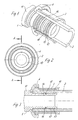
- FIG. 1 to 4 show a connection arrangement with a support tube 1, which is inserted with a nozzle 10 in a tube 2.
- the tube 2 can for example be designed as a composite pipe, while the nozzle 1 made of metal or plastic is made.
- the pipe 10 is connected to the pipe 10 protruding section 11, which has shoulders, which on the neck 10 subsequent shoulder forms a stop for the tube 2.
- a compression sleeve 3 is arranged around the tube 2, which is in the axial direction is held by a ring 4.
- the connector 10 comprises ribs 12, between which grooves 13 are formed.
- the material of the tube 2 digs into the grooves 13, so that the support tube 1 is secured in the tube 2 in the axial direction.
- a radial opening 14 is provided in the socket 10, which opens in the tube 2 allows the fluid to pass through to the outside.
- the fluid can flow from the opening 14 flow out in the unpressed state to section 11 of the support tube, so that an accidental forgetting of the pressing is recognized immediately.
- additional recesses can be provided or a corresponding one Surface roughness can be provided so that a fluid in the unpressed state can flow outwards.
- a pressing tool is used the compression sleeve 3 and presses the compression sleeve 3 together with the tube 2 against the support sleeve 1.
- material of the tube 2 reaches the mouth of the opening 14 and closes it permanently.
- the support tube 1 is secured against movement in the tube 2.
- a support tube 1 'with a Stub 10 'inserted into a tube 2 by a press ring and a fixing ring 4 is surrounded.
- a through opening 14' which protrude from the tube 2 in the axial direction through the support tube 1 ' Section 11 'extends. Fluid can therefore be in the unpressed state pass through the opening 14 'into the section 11', with corresponding Channels the fluid can escape to the outside, so that accidental forgetting of pressing can be recorded.
- the opening 14 ' is located just below the outer surface of the neck 10 ', on which in turn ribs 12' and grooves 13 'are formed.
- a sealing ring 15 is inserted, the opening 14' is arranged immediately adjacent to the annular receptacle 16 '.
- the one hand can compress the compression sleeve 3 and the tube 2 be closed by compressing the connector 10 'and on the other hand by pressing the sealing ring 15 into the opening 14 ', so that no fluid can escape to the outside after pressing.
- a flattened area 17 ' is provided on the outer circumference of the connecting piece 10', so that when pressing the pipe 2 is pressed against this flattening 17 'and the sealing ring 15 is pressed into the opening 14 to close the flow channel.
- the through opening is an axial channel, that forms a flow channel like a groove before pressing.
- the axial The channel or the longitudinal groove on the outer circumference of the connecting piece is then pressed closed and sealed by the tube 2.
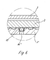
- FIG. 6 shows a third embodiment of a support tube 1 ′′, only the area of a continuous opening 14 "is shown as the others Elements of the connection arrangement outside of the range shown to those can correspond to FIG. 1.
- the continuous opening 14 extends from an inside of the support tube 1 "to a conically widening mouth section in the area of a sealing ring 15 on the outside of the support tube. This is in the unpressed state a gap between the sealing ring 15 and the support tube 1 "is formed, which acts as a flow channel acts and therefore a leak of a liquid or gaseous fluid from the Pipe 2 allows.
- Sealing ring 15 is pressed radially inward into the opening 14 ′′ and can be sealed close. Since the sealing ring has a slightly larger cross section than that Diameter of the opening 14 "outside the mouth section, can be secured Way a permanent seal can be achieved.
- only one opening 14 or 14 ' is in each case provided on the nozzle 10 '. It is also possible to have a plurality of openings 14 or 14 'to be provided in the axial and / or radial direction.
- the opening 14 can also extend obliquely in the support tube 1. It is also possible to without the support tube to form a sealing ring 15, since even a seal by the pressing itself can be achieved.
Landscapes
- Engineering & Computer Science (AREA)
- General Engineering & Computer Science (AREA)
- Mechanical Engineering (AREA)
- Quick-Acting Or Multi-Walled Pipe Joints (AREA)
- Non-Disconnectible Joints And Screw-Threaded Joints (AREA)
- Rigid Pipes And Flexible Pipes (AREA)
- Branch Pipes, Bends, And The Like (AREA)
- Earth Drilling (AREA)
- Gasket Seals (AREA)
- Pipeline Systems (AREA)
- Joints Allowing Movement (AREA)
- Supports For Pipes And Cables (AREA)
Abstract
Description
Die vorliegende Erfindung betrifft ein Stützrohr für eine Pressrohrverbindung, mit einem in ein Rohr einfügbaren Stutzen und einem sich daran anschließenden aus dem Rohr herausragenden Abschnitt, sowie eine Verbindungsanordnung mit einem verpressbarem Rohr.The present invention relates to a support pipe for a press pipe connection, with a connector that can be inserted into a pipe and an adjoining one the tube projecting section, as well as a connection arrangement with a compressible tube.
Zum Herstellen einer Pressverbindung sind Stützrohre bekannt, die in ein Rohr eingeschoben werden, um anschließend das Rohr auf die Stützhülse zu verpressen und somit eine abgedichtete Verbindung herzustellen. Das Rohr kann dabei als reines Kunststoffrohr oder als Verbundrohr ausgebildet sein und von einer Presshülse aus Metall umgeben sein. An der Stützhülse kann dann ein weiteres Bauteil, wie eine Armatur oder ein Fitting angeschlossen werden, um ein Leitungssystem zusammenzustellen. Nachteilig bei dieser Art der Verbindungstechnik ist, dass nach dem Einschieben der Stützhülse schon eine vorläufige Dichtung zwischen dem Rohr an der Stützhülse erreicht werden kann. Falls das Verpressen der Presshülse bzw. des Rohres vergessen wird, tritt die Undichtigkeit erst nach einiger Zeit auf und kann erhebliche Schäden herbeiführen. Support tubes are known for establishing a press connection, which are inserted into a tube to then press the tube onto the support sleeve and thus create a sealed connection. The tube can be as pure Plastic tube or be designed as a composite tube and from a compression sleeve Metal. Another component such as a can then be attached to the support sleeve Valve or fitting can be connected to assemble a pipe system. The disadvantage of this type of connection technology is that after insertion the support sleeve already has a preliminary seal between the tube on the Support sleeve can be achieved. If the compression of the compression sleeve or the tube is forgotten, the leak occurs after some time and can be significant Cause damage.
Es ist daher Aufgabe der vorliegenden Erfindung, ein Stützrohr für eine Pressrohrverbindung zu schaffen, das vor dem Verpressen eine gewollte Undichtigkeit bei Einfügung in ein Rohr erzeugt, die durch das Verpressen des Rohres abdichtbar ist.It is therefore an object of the present invention to provide a support tube for a press tube connection to create a deliberate leak before pressing Inserted into a tube, which can be sealed by pressing the tube.
Diese Aufgabe wird mit einem Stützrohr mit den Merkmalen des Anspruches 1 gelöst.This object is achieved with a support tube with the features of
Wenn in dem Stützrohr mindestens eine durchgehende Öffnung vorgesehen ist, die durch Verpressen des Rohres im Bereich des Stutzens abdichtbar ist, kann vor dem Verpressen ein Fluid aus dem Rohrleitungssystem nach außen treten, so dass ein versehentliches Vergessen des Verpressens umgehend entdeckt wird. Erst durch das Verpressen wird der durch die Öffnung gebildete Strömungskanal verschlossen, so dass eine dauerhaft dichte Verbindung bereitgestellt wird.If at least one through opening is provided in the support tube, the can be sealed by pressing the pipe in the area of the nozzle, before Squeezing a fluid outward from the piping system so that a accidental forgetting of pressing is discovered immediately. Only through that The flow channel formed by the opening is pressed, see above that a permanently tight connection is provided.
Gemäß einer bevorzugten Ausführungsform der Erfindung ist die durchgehende Öffnung im wesentlichen in radialer Richtung in dem Stutzen ausgebildet und wird dann beim Verpressen durch das Rohr verschlossen. Durch die Ausbildung in radialer Richtung kann Material des Rohres in die Mündung der Öffnung hineingedrückt werden, so dass die Öffnung stopfenartig verschlossen wird.According to a preferred embodiment of the invention, the is continuous Opening is substantially formed in the nozzle in the radial direction then closed by the tube during pressing. By training in radial Direction material of the tube can be pressed into the mouth of the opening so that the opening is closed like a stopper.
Gemäß einer weiteren Ausführungsform erstreckt sich die durchgehende Öffnung im wesentlichen in axialer Richtung durch den Stutzen und wird beim Verpressen durch eine Verformung des Stutzens verschlossen. Dabei kann die Öffnung dicht unterhalb der äußeren Oberfläche des Stutzens ausgebildet sein, damit auch geringe Presskräfte ausreichen, um die axiale Öffnung zu verschließen.According to a further embodiment, the through opening extends essentially in the axial direction through the nozzle and is during pressing closed by deformation of the nozzle. The opening can be tight be formed below the outer surface of the nozzle, so that even small Press forces are sufficient to close the axial opening.
Vorzugsweise besitzt die Öffnung oder besitzen die Öffnungen einen Durchmesser von 0,1 bis 3 mm, abhängig vom Einsatzzweck und dem Material des Stützrohres.The opening or the openings preferably have a diameter from 0.1 to 3 mm, depending on the application and the material of the support tube.
Um eine stabile Pressverbindung herstellen zu können, sind vorzugsweise an dem Stutzen Rippen angeformt, die sich beim Verpressen in das Material des Rohres eingraben. Dabei kann zwischen den Rippen auch eine ringförmige Vertiefung zur Aufnahme eines Dichtringes vorgesehen sein. Eine radiale Öffnung befindet sich dann bevorzugt an der zum Rohrende hin gewandten Seite des Dichtringes.In order to be able to produce a stable press connection, are preferably on Connection ribs formed, which are pressed into the material of the tube dig. An annular recess can also be between the ribs Recording a sealing ring may be provided. There is a radial opening then preferably on the side of the sealing ring facing the pipe end.
Gemäß einer weiteren Ausführungsform erstreckt sich die Öffnung von einer Innenseite des Stützrohres zu einem Dichtring an einer Außenseite des Stützrohres, wobei durch die Öffnung im unverpressten Zustand ein Strömungskanal zwischen Innenseite und Außenseite des Stützrohres gebildet ist. Beim Verpressen kann somit eine Abdichtung durch Eindrücken des Dichtringes in die Öffnung erfolgen. Der Strömungskanal wird vorzugsweise dadurch gebildet, dass der äußere Mündungsabschnitt der Öffnung sich im Bereich des Dichtringes konisch erweitert, so dass ein Spalt zwischen Dichtring und Stützrohr im unverpressten Zustand gebildet ist.According to a further embodiment, the opening extends from an inside of the support tube to form a sealing ring on an outside of the support tube, wherein through the opening in the unpressed state, a flow channel between the inside and outside of the support tube is formed. When pressing, one can Sealing is done by pressing the sealing ring into the opening. The flow channel is preferably formed in that the outer mouth section the opening widens conically in the area of the sealing ring, so that a Gap between the sealing ring and the support tube is formed in the unpressed state.
Wenn die Öffnung unterhalb des Dichtringes einen kleineren Querschnitt besitzt als der Dichtring, kann auf einfache Weise beim Verpressen der Dichtring in die Öffnung gedrückt werden, um eine dauerhafte sichere Abdichtung zu erreichen.If the opening below the sealing ring has a smaller cross section than the sealing ring, can be easily pressed into the opening when the sealing ring is pressed pressed to achieve a permanent, secure seal.
Das Stützrohr ist bevorzugt aus Metall oder Kunststoff ausgebildet, wobei auch andere geeignete Materialien zum Einsatz kommen können.The support tube is preferably made of metal or plastic, but also others suitable materials can be used.
Die Erfindung wird nachfolgend anhand von drei Ausführungsbeispielen mit Bezug auf die beigefügten Zeichnungen näher erläutert. Es zeigen:
- Fig. 1
- eine perspektivische teilweise geschnittene Ansicht eines ersten Ausführungsbeispieles eines erfindungsgemäßen Stützrohres im montierten Zustand;
- Fig. 2
- eine Querschnittsansicht des montierten Stützrohres der Fig. 1;
- Fig. 3
- eine geschnittene Seitenansicht entlang der Linie A-A der Fig. 2;
- Fig. 4
- eine perspektivische Ansicht des Stützrohres der Fig. 1;
- Fig. 5
- eine geschnittene Seitenansicht eines zweiten Ausführungs-beispieles eines erfindungsgemäßen Stützrohres im montierten Zustand, und
- Fig. 6
- eine Detailansicht eines dritten Ausführungsbeispiels.
- Fig. 1
- a perspective partially sectioned view of a first embodiment of a support tube according to the invention in the assembled state;
- Fig. 2
- a cross-sectional view of the assembled support tube of Fig. 1;
- Fig. 3
- a sectional side view along the line AA of Fig. 2;
- Fig. 4
- a perspective view of the support tube of Fig. 1;
- Fig. 5
- a sectional side view of a second embodiment example of a support tube according to the invention in the assembled state, and
- Fig. 6
- a detailed view of a third embodiment.
In den Figuren 1 bis 4 ist eine Verbindungsanordnung mit einem Stützrohr 1 gezeigt,
das mit einem Stutzen 10 in einem Rohr 2 eingefügt ist. Das Rohr 2 kann beispielsweise
als Verbundrohr ausgebildet sein, während der Stutzen 1 aus Metall
oder Kunststoff hergestellt ist. An den Stutzen 10 schließt sich ein aus dem Rohr 2
herausragender Abschnitt 11 an, der Schultern aufweist, wobei die an den Stutzen
10 anschließende Schulter einen Anschlag für das Rohr 2 bildet. In dem Bereich des
Stutzens 10 ist eine Presshülse 3 um das Rohr 2 angeordnet, die in axialer Richtung
durch einen Ring 4 gehalten ist.1 to 4 show a connection arrangement with a
Der Stutzen 10 umfasst Rippen 12, zwischen denen Rillen 13 ausgebildet sind.
Beim Verpressen gräbt sich das Material des Rohres 2 in die Rillen 13 ein, so dass
das Stützrohr 1 in axialer Richtung in dem Rohr 2 gesichert ist. Ferner ist eine ringförmige
Vertiefung 16 in dem Stützrohr 1 ausgebildet, in der ein Dichtring 15 aus
elastischem Material aufgenommen ist.The
In dem Stutzen 10 ist eine radiale Öffnung 14 vorgesehen, die ein in dem Rohr 2
befindliches Fluid nach außen durchtreten lässt. Von der Öffnung 14 kann das Fluid
im unverpressten Zustand zu dem Abschnitt 11 des Stützrohres ausströmen, so dass
ein versehentliches Vergessen des Verpressens umgehend erkannt wird. An den
Rippen 12 zwischen der Öffnung 14 und dem aus dem Rohr 2 ragenden Abschnitt
11 können zusätzliche Ausnehmungen vorgesehen sein oder eine entsprechende
Oberflächenrauhigkeit vorgesehen werden, damit ein Fluid im unverpressten Zustand
nach außen abströmen kann. A
Um die gezeigte Verbindungsanordnung abzudichten, greift ein Presswerkzeug um
die Presshülse 3 und verpresst die Presshülse 3 zusammen mit dem Rohr 2 gegen
die Stützhülse 1. Dadurch gelangt Material des Rohres 2 in die Mündung der Öffnung
14 und verschließt diese dauerhaft. Durch die Profilierungen am Stutzen 10
des Stützrohres 1 ist das Stützrohr 1 gegen eine Bewegung in dem Rohr 2 gesichert.In order to seal the connection arrangement shown, a pressing tool is used
the
Bei dem in Fig. 5 gezeigten Ausführungsbeispiel ist ein Stützrohr 1' mit einem
Stutzen 10' in ein Rohr 2 eingesteckt, das von einem Pressring und einem Fixierring
4 umgeben ist. In dem Stützrohr 1' ist eine durchgehende Öffnung 14' ausgespart,
die sich in axialer Richtung durch das Stützrohr 1' bis in den aus dem Rohr 2 herausragenden
Abschnitt 11' erstreckt. Im unverpressten Zustand kann daher Fluid
durch die Öffnung 14' bis in den Abschnitt 11' gelangen, wobei durch entsprechende
Kanäle das Fluid nach außen austreten kann, damit ein versehentliches Vergessen
des Verpressens erfasst werden kann.In the embodiment shown in FIG. 5, a support tube 1 'with a
Stub 10 'inserted into a
Die Öffnung 14' befindet sich dicht unterhalb der äußeren Oberfläche des Stutzens
10', an dem wiederum Rippen 12' und Rillen 13' angeformt sind. Im Bereich einer
ringförmigen Aufnahme 16' ist ein Dichtring 15 eingelegt, wobei die Öffnung 14'
unmittelbar benachbart zu der ringförmigen Aufnahme 16' angeordnet ist. Beim
Verpressen der Presshülse 3 und des Rohres 2 kann die Öffnnung 14' einerseits
durch Zusammendrücken des Stutzens 10' verschlossen werden und andererseits
durch Eindrücken des Dichtringes 15 in die Öffnung 14' abgedichtet werden, so
dass nach dem Verpressen kein Fluid mehr nach außen austreten kann. Im Bereich
der einen Strömungskanal bildenden Öffnung 14' und des Dichtringes 15 ist am
Außenumfang des Stutzens 10' eine Abflachung 17' vorgesehen, so dass beim Verpressen
das Rohr 2 gegen diese Abflachung 17' gepresst wird und der Dichtring 15
dabei in die Öffnung 14 eingedrückt wird, um den Strömungskanal zu verschließen.The opening 14 'is located just below the outer surface of the neck
10 ', on which in turn ribs 12' and grooves 13 'are formed. In the area of one
ring-shaped receptacle 16 ', a sealing
Ferner ist es möglich, die durchgehende Öffnung als einen axialen Kanal auszubilden,
der wie eine Nut einen Strömungskanal vor dem Verpressen bildet. Der axiale
Kanal bzw. die Längsnut am äußeren Umfang des Stutzens wird dann beim Verpressen
durch das Rohr 2 verschlossen und abgedichtet.Furthermore, it is possible to design the through opening as an axial channel,
that forms a flow channel like a groove before pressing. The axial
The channel or the longitudinal groove on the outer circumference of the connecting piece is then pressed
closed and sealed by the
In Fig. 6 ist eine dritte Ausführungsform eines Stützrohres 1" gezeigt, wobei lediglich
der Bereich einer durchgehenden Öffnung 14" dargestellt ist, da die übrigen
Elemente der Verbindungsanordnung außerhalb des dargestellten Bereiches denjenigen
der Fig. 1 entsprechen können.6 shows a third embodiment of a
Die durchgehende Öffnung 14" erstreckt sich von einer Innenseite des Stützrohres
1" zu einem sich konisch erweiternden Mündungsabschnitt im Bereich eines Dichtringes
15 an der Außenseite des Stützrohres. Dadurch ist im unverpressten Zustand
ein Spalt zwischen Dichtring 15 und Stützrohr 1" gebildet, der als Strömungskanal
wirkt und daher ein Austreten eines flüssigen oder gasförmigen Fluides aus dem
Rohr 2 ermöglicht. Durch Verpressen der Stützhülse 3 und des Rohres 2 wird der
Dichtring 15 radial nach innen in die Öffnung 14" gedrückt und kann diese dicht
verschließen. Da der Dichtring einen etwas größeren Querschnitt besitzt als der
Durchmesser der Öffnung 14" außerhalb des Mündungsabschnittes, kann auf sichere
Weise eine dauerhafte Abdichtung erzielt werden.The
In den dargestellten Ausführungsbeispielen ist jeweils nur eine Öffnung 14 bzw. 14'
an dem Stutzen 10' vorgesehen. Es ist auch möglich, mehrere Öffnungen 14 bzw.
14' in axialer und/oder radialer Richtung vorzusehen. Die Öffnung 14 kann sich
auch schräg in dem Stützrohr 1 erstrecken. Ferner ist es möglich, das Stützrohr ohne
einen Dichtring 15 auszubilden, da auch durch das Verpressen selbst eine Abdichtung
erzielt werden kann.In the illustrated exemplary embodiments, only one
Claims (12)
Priority Applications (1)
| Application Number | Priority Date | Filing Date | Title |
|---|---|---|---|
| DK02010900T DK1265018T3 (en) | 2001-06-07 | 2002-05-16 | Pipe connection device |
Applications Claiming Priority (4)
| Application Number | Priority Date | Filing Date | Title |
|---|---|---|---|
| DE20109547U | 2001-06-07 | ||
| DE20109547 | 2001-06-07 | ||
| DE20201072U DE20201072U1 (en) | 2001-06-07 | 2002-01-25 | Connection tube with connecting device has at least one through aperture in connection tube which can be sealed by pressing home tube |
| DE20201072U | 2002-01-25 |
Publications (2)
| Publication Number | Publication Date |
|---|---|
| EP1265018A1 true EP1265018A1 (en) | 2002-12-11 |
| EP1265018B1 EP1265018B1 (en) | 2005-06-29 |
Family
ID=7957867
Family Applications (1)
| Application Number | Title | Priority Date | Filing Date |
|---|---|---|---|
| EP02010900A Expired - Lifetime EP1265018B1 (en) | 2001-06-07 | 2002-05-16 | Pipe assembly arrangement |
Country Status (6)
| Country | Link |
|---|---|
| EP (1) | EP1265018B1 (en) |
| AT (1) | ATE298857T1 (en) |
| DE (2) | DE20201072U1 (en) |
| DK (1) | DK1265018T3 (en) |
| ES (1) | ES2242800T3 (en) |
| PT (1) | PT1265018E (en) |
Cited By (10)
| Publication number | Priority date | Publication date | Assignee | Title |
|---|---|---|---|---|
| EP1775507A1 (en) * | 2005-10-12 | 2007-04-18 | Roth Werke GmbH | Fitting for pipes |
| EP1882876A1 (en) * | 2006-07-26 | 2008-01-30 | I.V.A.R. S.P.A. | Device for joining ducts, in particular for flexible ducts |
| EP1930640A1 (en) | 2006-12-06 | 2008-06-11 | Uponor Innovation Ab | Fitting for a pipe, in particular plastic pipe or plastic-metal composite pipe |
| EP2020552A1 (en) * | 2007-08-01 | 2009-02-04 | VIEGA GmbH & Co. KG. | Tubular component |
| WO2011114209A1 (en) * | 2010-03-15 | 2011-09-22 | Eaton Corporation | Hose coupling |
| US9027966B2 (en) | 2009-12-16 | 2015-05-12 | Uponor Innovation Ab | Fitting for a pipe |
| US9551445B2 (en) | 2014-06-09 | 2017-01-24 | Cooper Technologies Company | Conduit receivers |
| EP3232109A1 (en) * | 2016-04-11 | 2017-10-18 | Viega Technology GmbH & Co. KG | Piping system with protection against fire and use of such a system |
| US10302230B2 (en) | 2014-06-09 | 2019-05-28 | Eaton Intelligent Power Limited | Field serviceable conduit receivers |
| CN113508256A (en) * | 2019-02-18 | 2021-10-15 | I.V.A.R.股份有限公司 | Fitting for connecting pipes, in particular flexible pipes |
Citations (3)
| Publication number | Priority date | Publication date | Assignee | Title |
|---|---|---|---|---|
| US3984988A (en) * | 1974-11-07 | 1976-10-12 | Soletanche | Obturating device, especially for injection tubes |
| DE19817136A1 (en) * | 1998-04-17 | 1999-10-21 | Georg Jaeggi | Combined metal-plastics pipe system incorporating corrosion protection |
| DE19929010C1 (en) * | 1999-06-24 | 2000-11-23 | Kirchner Fraenk Rohr | Pipe connection has a molded plastics body to hold the pipe connector with a press sleeve and a support sleeve with a free zone to allow a slight bend or tilt in the assembly |
Family Cites Families (1)
| Publication number | Priority date | Publication date | Assignee | Title |
|---|---|---|---|---|
| DE9110998U1 (en) * | 1991-09-05 | 1991-10-31 | Hewing GmbH, 4434 Ochtrup | Pipe connection |
-
2002
- 2002-01-25 DE DE20201072U patent/DE20201072U1/en not_active Expired - Lifetime
- 2002-05-16 AT AT02010900T patent/ATE298857T1/en not_active IP Right Cessation
- 2002-05-16 DK DK02010900T patent/DK1265018T3/en active
- 2002-05-16 PT PT02010900T patent/PT1265018E/en unknown
- 2002-05-16 DE DE50203479T patent/DE50203479D1/en not_active Expired - Fee Related
- 2002-05-16 ES ES02010900T patent/ES2242800T3/en not_active Expired - Lifetime
- 2002-05-16 EP EP02010900A patent/EP1265018B1/en not_active Expired - Lifetime
Patent Citations (3)
| Publication number | Priority date | Publication date | Assignee | Title |
|---|---|---|---|---|
| US3984988A (en) * | 1974-11-07 | 1976-10-12 | Soletanche | Obturating device, especially for injection tubes |
| DE19817136A1 (en) * | 1998-04-17 | 1999-10-21 | Georg Jaeggi | Combined metal-plastics pipe system incorporating corrosion protection |
| DE19929010C1 (en) * | 1999-06-24 | 2000-11-23 | Kirchner Fraenk Rohr | Pipe connection has a molded plastics body to hold the pipe connector with a press sleeve and a support sleeve with a free zone to allow a slight bend or tilt in the assembly |
Cited By (12)
| Publication number | Priority date | Publication date | Assignee | Title |
|---|---|---|---|---|
| EP1775507A1 (en) * | 2005-10-12 | 2007-04-18 | Roth Werke GmbH | Fitting for pipes |
| EP1882876A1 (en) * | 2006-07-26 | 2008-01-30 | I.V.A.R. S.P.A. | Device for joining ducts, in particular for flexible ducts |
| EP1930640A1 (en) | 2006-12-06 | 2008-06-11 | Uponor Innovation Ab | Fitting for a pipe, in particular plastic pipe or plastic-metal composite pipe |
| EP2020552A1 (en) * | 2007-08-01 | 2009-02-04 | VIEGA GmbH & Co. KG. | Tubular component |
| US9027966B2 (en) | 2009-12-16 | 2015-05-12 | Uponor Innovation Ab | Fitting for a pipe |
| WO2011114209A1 (en) * | 2010-03-15 | 2011-09-22 | Eaton Corporation | Hose coupling |
| US8888138B2 (en) | 2010-03-15 | 2014-11-18 | Eaton Corporation | Hose coupling |
| US9551445B2 (en) | 2014-06-09 | 2017-01-24 | Cooper Technologies Company | Conduit receivers |
| US9800030B2 (en) | 2014-06-09 | 2017-10-24 | Cooper Technologies Company | Conduit receivers |
| US10302230B2 (en) | 2014-06-09 | 2019-05-28 | Eaton Intelligent Power Limited | Field serviceable conduit receivers |
| EP3232109A1 (en) * | 2016-04-11 | 2017-10-18 | Viega Technology GmbH & Co. KG | Piping system with protection against fire and use of such a system |
| CN113508256A (en) * | 2019-02-18 | 2021-10-15 | I.V.A.R.股份有限公司 | Fitting for connecting pipes, in particular flexible pipes |
Also Published As
| Publication number | Publication date |
|---|---|
| PT1265018E (en) | 2005-08-31 |
| EP1265018B1 (en) | 2005-06-29 |
| ATE298857T1 (en) | 2005-07-15 |
| DE20201072U1 (en) | 2003-01-09 |
| ES2242800T3 (en) | 2005-11-16 |
| DE50203479D1 (en) | 2005-08-04 |
| DK1265018T3 (en) | 2005-09-05 |
Similar Documents
| Publication | Publication Date | Title |
|---|---|---|
| DE10007914C1 (en) | Fitting or fitting for establishing a press connection with an inserted pipe end | |
| EP1456574B1 (en) | Connection piece for fluid lines and device embodied thereas | |
| DE4006276C2 (en) | Hydraulic underwater coupling | |
| DE20207313U1 (en) | Connector and connector assembly | |
| EP1593899A1 (en) | Compression fitting arrangement | |
| DE4101757A1 (en) | CONNECTOR FOR CONNECTING A THIN PIPE | |
| DE60305236T2 (en) | Connecting device for connecting two pipes | |
| DE19740144A1 (en) | Connection of a metal pipe with a metal sleeve | |
| EP1319451A1 (en) | Supporting system for a wall element, in particular for a lid or container wall element | |
| DE69931773T2 (en) | pipe connection | |
| EP0190388B1 (en) | Squeeze connector | |
| EP1265018B1 (en) | Pipe assembly arrangement | |
| EP1046855B1 (en) | Quick-acting coupling | |
| EP1441165B1 (en) | Press-connection arrangement | |
| DE10164568C1 (en) | Overlapping connection with seal for ends of pipes has sleeve with inside diameter slightly greater than outside diameter of end of pipe, with expanded end accommodating O-ring | |
| EP1265019B1 (en) | Supporting tube and connector assembly | |
| DE69300779T2 (en) | Improvements to pipe connections. | |
| DE3833535C2 (en) | Pipe coupling | |
| EP0390747A2 (en) | Sealing connection for multilayer plastic pipes | |
| DE10108309C1 (en) | Pipe coupling for deformable pipe incorporates deformable plastics seal moved in opposite direction to pipe end by axial compression | |
| DE19728137C1 (en) | Plug connection for pipe conduits | |
| EP1431643A1 (en) | Pressfitting and holding element for a pressfitting joint | |
| DE10202790A1 (en) | Pipe coupling Press | |
| DE20002952U1 (en) | Fitting or fitting for establishing a press connection with an inserted pipe end | |
| DE4241817C2 (en) | Connection device for pipe and / or hose lines |
Legal Events
| Date | Code | Title | Description |
|---|---|---|---|
| PUAI | Public reference made under article 153(3) epc to a published international application that has entered the european phase |
Free format text: ORIGINAL CODE: 0009012 |
|
| AK | Designated contracting states |
Kind code of ref document: A1 Designated state(s): AT BE CH CY DE DK ES FI FR GB GR IE IT LI LU MC NL PT SE TR |
|
| AX | Request for extension of the european patent |
Free format text: AL;LT;LV;MK;RO;SI |
|
| 17P | Request for examination filed |
Effective date: 20021223 |
|
| 17Q | First examination report despatched |
Effective date: 20030714 |
|
| AKX | Designation fees paid |
Designated state(s): AT BE CH CY DE DK ES FI FR GB GR IE IT LI LU MC NL PT SE TR |
|
| RAP1 | Party data changed (applicant data changed or rights of an application transferred) |
Owner name: NUSSBAUM AG METALLGIESSEREI UND ARMATURENFABRIK Owner name: VIEGA GMBH & CO. KG. |
|
| RTI1 | Title (correction) |
Free format text: PIPE ASSEMBLY ARRANGEMENT |
|
| GRAP | Despatch of communication of intention to grant a patent |
Free format text: ORIGINAL CODE: EPIDOSNIGR1 |
|
| GRAS | Grant fee paid |
Free format text: ORIGINAL CODE: EPIDOSNIGR3 |
|
| GRAA | (expected) grant |
Free format text: ORIGINAL CODE: 0009210 |
|
| AK | Designated contracting states |
Kind code of ref document: B1 Designated state(s): AT BE CH CY DE DK ES FI FR GB GR IE IT LI LU MC NL PT SE TR |
|
| PG25 | Lapsed in a contracting state [announced via postgrant information from national office to epo] |
Ref country code: TR Free format text: LAPSE BECAUSE OF FAILURE TO SUBMIT A TRANSLATION OF THE DESCRIPTION OR TO PAY THE FEE WITHIN THE PRESCRIBED TIME-LIMIT Effective date: 20050629 Ref country code: IE Free format text: LAPSE BECAUSE OF FAILURE TO SUBMIT A TRANSLATION OF THE DESCRIPTION OR TO PAY THE FEE WITHIN THE PRESCRIBED TIME-LIMIT Effective date: 20050629 |
|
| REG | Reference to a national code |
Ref country code: GB Ref legal event code: FG4D Free format text: NOT ENGLISH |
|
| REG | Reference to a national code |
Ref country code: CH Ref legal event code: EP |
|
| REG | Reference to a national code |
Ref country code: CH Ref legal event code: NV Representative=s name: DR.THOMAS STEPHAN MARTIN, WEBER & PARTNER |
|
| REF | Corresponds to: |
Ref document number: 50203479 Country of ref document: DE Date of ref document: 20050804 Kind code of ref document: P |
|
| REG | Reference to a national code |
Ref country code: IE Ref legal event code: FG4D Free format text: LANGUAGE OF EP DOCUMENT: GERMAN |
|
| REG | Reference to a national code |
Ref country code: SE Ref legal event code: TRGR |
|
| REG | Reference to a national code |
Ref country code: PT Ref legal event code: SC4A Effective date: 20050711 |
|
| REG | Reference to a national code |
Ref country code: DK Ref legal event code: T3 |
|
| GBT | Gb: translation of ep patent filed (gb section 77(6)(a)/1977) |
Effective date: 20050826 |
|
| PG25 | Lapsed in a contracting state [announced via postgrant information from national office to epo] |
Ref country code: GR Free format text: LAPSE BECAUSE OF FAILURE TO SUBMIT A TRANSLATION OF THE DESCRIPTION OR TO PAY THE FEE WITHIN THE PRESCRIBED TIME-LIMIT Effective date: 20050929 |
|
| REG | Reference to a national code |
Ref country code: ES Ref legal event code: FG2A Ref document number: 2242800 Country of ref document: ES Kind code of ref document: T3 |
|
| REG | Reference to a national code |
Ref country code: IE Ref legal event code: FD4D |
|
| ET | Fr: translation filed | ||
| PLBE | No opposition filed within time limit |
Free format text: ORIGINAL CODE: 0009261 |
|
| STAA | Information on the status of an ep patent application or granted ep patent |
Free format text: STATUS: NO OPPOSITION FILED WITHIN TIME LIMIT |
|
| PG25 | Lapsed in a contracting state [announced via postgrant information from national office to epo] |
Ref country code: MC Free format text: LAPSE BECAUSE OF NON-PAYMENT OF DUE FEES Effective date: 20060531 |
|
| 26N | No opposition filed |
Effective date: 20060330 |
|
| REG | Reference to a national code |
Ref country code: CH Ref legal event code: NV Representative=s name: TROESCH SCHEIDEGGER WERNER AG |
|
| PG25 | Lapsed in a contracting state [announced via postgrant information from national office to epo] |
Ref country code: LU Free format text: LAPSE BECAUSE OF NON-PAYMENT OF DUE FEES Effective date: 20060516 |
|
| PGFP | Annual fee paid to national office [announced via postgrant information from national office to epo] |
Ref country code: CH Payment date: 20080521 Year of fee payment: 7 Ref country code: DE Payment date: 20080521 Year of fee payment: 7 Ref country code: DK Payment date: 20080526 Year of fee payment: 7 Ref country code: ES Payment date: 20080523 Year of fee payment: 7 |
|
| PGFP | Annual fee paid to national office [announced via postgrant information from national office to epo] |
Ref country code: AT Payment date: 20080527 Year of fee payment: 7 |
|
| PGFP | Annual fee paid to national office [announced via postgrant information from national office to epo] |
Ref country code: PT Payment date: 20080430 Year of fee payment: 7 Ref country code: FI Payment date: 20080522 Year of fee payment: 7 Ref country code: BE Payment date: 20080606 Year of fee payment: 7 Ref country code: IT Payment date: 20080527 Year of fee payment: 7 |
|
| PGFP | Annual fee paid to national office [announced via postgrant information from national office to epo] |
Ref country code: NL Payment date: 20080531 Year of fee payment: 7 Ref country code: SE Payment date: 20080521 Year of fee payment: 7 |
|
| PG25 | Lapsed in a contracting state [announced via postgrant information from national office to epo] |
Ref country code: CY Free format text: LAPSE BECAUSE OF FAILURE TO SUBMIT A TRANSLATION OF THE DESCRIPTION OR TO PAY THE FEE WITHIN THE PRESCRIBED TIME-LIMIT Effective date: 20050629 |
|
| PGFP | Annual fee paid to national office [announced via postgrant information from national office to epo] |
Ref country code: FR Payment date: 20080521 Year of fee payment: 7 |
|
| PGFP | Annual fee paid to national office [announced via postgrant information from national office to epo] |
Ref country code: GB Payment date: 20080521 Year of fee payment: 7 |
|
| REG | Reference to a national code |
Ref country code: PT Ref legal event code: MM4A Free format text: LAPSE DUE TO NON-PAYMENT OF FEES Effective date: 20091116 |
|
| BERE | Be: lapsed |
Owner name: *VIEGA G.M.B.H. & CO. K.G. Effective date: 20090531 Owner name: *NUSSBAUM A.G. METALLGIESSEREI UND ARMATURENFABRIK Effective date: 20090531 |
|
| REG | Reference to a national code |
Ref country code: CH Ref legal event code: PL |
|
| REG | Reference to a national code |
Ref country code: DK Ref legal event code: EBP |
|
| GBPC | Gb: european patent ceased through non-payment of renewal fee |
Effective date: 20090516 |
|
| PG25 | Lapsed in a contracting state [announced via postgrant information from national office to epo] |
Ref country code: LI Free format text: LAPSE BECAUSE OF NON-PAYMENT OF DUE FEES Effective date: 20090531 Ref country code: FI Free format text: LAPSE BECAUSE OF NON-PAYMENT OF DUE FEES Effective date: 20090516 Ref country code: CH Free format text: LAPSE BECAUSE OF NON-PAYMENT OF DUE FEES Effective date: 20090531 Ref country code: AT Free format text: LAPSE BECAUSE OF NON-PAYMENT OF DUE FEES Effective date: 20090516 |
|
| NLV4 | Nl: lapsed or anulled due to non-payment of the annual fee |
Effective date: 20091201 |
|
| PG25 | Lapsed in a contracting state [announced via postgrant information from national office to epo] |
Ref country code: NL Free format text: LAPSE BECAUSE OF NON-PAYMENT OF DUE FEES Effective date: 20091201 |
|
| REG | Reference to a national code |
Ref country code: FR Ref legal event code: ST Effective date: 20100129 |
|
| PG25 | Lapsed in a contracting state [announced via postgrant information from national office to epo] |
Ref country code: PT Free format text: LAPSE BECAUSE OF NON-PAYMENT OF DUE FEES Effective date: 20091116 |
|
| PG25 | Lapsed in a contracting state [announced via postgrant information from national office to epo] |
Ref country code: DK Free format text: LAPSE BECAUSE OF NON-PAYMENT OF DUE FEES Effective date: 20090531 Ref country code: FR Free format text: LAPSE BECAUSE OF NON-PAYMENT OF DUE FEES Effective date: 20090602 |
|
| PG25 | Lapsed in a contracting state [announced via postgrant information from national office to epo] |
Ref country code: GB Free format text: LAPSE BECAUSE OF NON-PAYMENT OF DUE FEES Effective date: 20090516 |
|
| PG25 | Lapsed in a contracting state [announced via postgrant information from national office to epo] |
Ref country code: DE Free format text: LAPSE BECAUSE OF NON-PAYMENT OF DUE FEES Effective date: 20091201 Ref country code: BE Free format text: LAPSE BECAUSE OF NON-PAYMENT OF DUE FEES Effective date: 20090531 |
|
| REG | Reference to a national code |
Ref country code: ES Ref legal event code: FD2A Effective date: 20090518 |
|
| PG25 | Lapsed in a contracting state [announced via postgrant information from national office to epo] |
Ref country code: ES Free format text: LAPSE BECAUSE OF NON-PAYMENT OF DUE FEES Effective date: 20090518 |
|
| PG25 | Lapsed in a contracting state [announced via postgrant information from national office to epo] |
Ref country code: IT Free format text: LAPSE BECAUSE OF NON-PAYMENT OF DUE FEES Effective date: 20090516 |
|
| PG25 | Lapsed in a contracting state [announced via postgrant information from national office to epo] |
Ref country code: SE Free format text: LAPSE BECAUSE OF NON-PAYMENT OF DUE FEES Effective date: 20090517 |