EP1264992B1 - A rheological fluid actuator for a lock - Google Patents
A rheological fluid actuator for a lock Download PDFInfo
- Publication number
- EP1264992B1 EP1264992B1 EP02253319A EP02253319A EP1264992B1 EP 1264992 B1 EP1264992 B1 EP 1264992B1 EP 02253319 A EP02253319 A EP 02253319A EP 02253319 A EP02253319 A EP 02253319A EP 1264992 B1 EP1264992 B1 EP 1264992B1
- Authority
- EP
- European Patent Office
- Prior art keywords
- fluid
- door latch
- state
- piston
- door
- Prior art date
- Legal status (The legal status is an assumption and is not a legal conclusion. Google has not performed a legal analysis and makes no representation as to the accuracy of the status listed.)
- Expired - Lifetime
Links
- 239000012530 fluid Substances 0.000 title claims description 36
- 230000007246 mechanism Effects 0.000 claims description 36
- 230000033001 locomotion Effects 0.000 claims description 10
- 230000008878 coupling Effects 0.000 description 3
- 238000010168 coupling process Methods 0.000 description 3
- 238000005859 coupling reaction Methods 0.000 description 3
- 101100136840 Dictyostelium discoideum plip gene Proteins 0.000 description 1
- 101150103491 Ptpmt1 gene Proteins 0.000 description 1
- 230000004075 alteration Effects 0.000 description 1
- 230000008901 benefit Effects 0.000 description 1
- 230000005540 biological transmission Effects 0.000 description 1
- 230000008859 change Effects 0.000 description 1
- 230000001010 compromised effect Effects 0.000 description 1
- 238000010586 diagram Methods 0.000 description 1
- 238000006073 displacement reaction Methods 0.000 description 1
- 239000000428 dust Substances 0.000 description 1
- 239000007788 liquid Substances 0.000 description 1
- 239000010705 motor oil Substances 0.000 description 1
- 239000003921 oil Substances 0.000 description 1
- 239000002245 particle Substances 0.000 description 1
- 238000007789 sealing Methods 0.000 description 1
- 239000000725 suspension Substances 0.000 description 1
Images


Classifications
-
- E—FIXED CONSTRUCTIONS
- E05—LOCKS; KEYS; WINDOW OR DOOR FITTINGS; SAFES
- E05B—LOCKS; ACCESSORIES THEREFOR; HANDCUFFS
- E05B51/00—Operating or controlling locks or other fastening devices by other non-mechanical means
- E05B51/02—Operating or controlling locks or other fastening devices by other non-mechanical means by pneumatic or hydraulic means
-
- F—MECHANICAL ENGINEERING; LIGHTING; HEATING; WEAPONS; BLASTING
- F15—FLUID-PRESSURE ACTUATORS; HYDRAULICS OR PNEUMATICS IN GENERAL
- F15B—SYSTEMS ACTING BY MEANS OF FLUIDS IN GENERAL; FLUID-PRESSURE ACTUATORS, e.g. SERVOMOTORS; DETAILS OF FLUID-PRESSURE SYSTEMS, NOT OTHERWISE PROVIDED FOR
- F15B21/00—Common features of fluid actuator systems; Fluid-pressure actuator systems or details thereof, not covered by any other group of this subclass
- F15B21/06—Use of special fluids, e.g. liquid metal; Special adaptations of fluid-pressure systems, or control of elements therefor, to the use of such fluids
- F15B21/065—Use of electro- or magnetosensitive fluids, e.g. electrorheological fluid
-
- F—MECHANICAL ENGINEERING; LIGHTING; HEATING; WEAPONS; BLASTING
- F16—ENGINEERING ELEMENTS AND UNITS; GENERAL MEASURES FOR PRODUCING AND MAINTAINING EFFECTIVE FUNCTIONING OF MACHINES OR INSTALLATIONS; THERMAL INSULATION IN GENERAL
- F16F—SPRINGS; SHOCK-ABSORBERS; MEANS FOR DAMPING VIBRATION
- F16F9/00—Springs, vibration-dampers, shock-absorbers, or similarly-constructed movement-dampers using a fluid or the equivalent as damping medium
- F16F9/32—Details
- F16F9/53—Means for adjusting damping characteristics by varying fluid viscosity, e.g. electromagnetically
-
- E—FIXED CONSTRUCTIONS
- E05—LOCKS; KEYS; WINDOW OR DOOR FITTINGS; SAFES
- E05B—LOCKS; ACCESSORIES THEREFOR; HANDCUFFS
- E05B47/00—Operating or controlling locks or other fastening devices by electric or magnetic means
- E05B47/0001—Operating or controlling locks or other fastening devices by electric or magnetic means with electric actuators; Constructional features thereof
- E05B2047/0014—Constructional features of actuators or power transmissions therefor
- E05B2047/0018—Details of actuator transmissions
- E05B2047/0026—Clutches, couplings or braking arrangements
- E05B2047/0033—Clutches, couplings or braking arrangements using electro-rheological or magneto-rheological substances
-
- E—FIXED CONSTRUCTIONS
- E05—LOCKS; KEYS; WINDOW OR DOOR FITTINGS; SAFES
- E05B—LOCKS; ACCESSORIES THEREFOR; HANDCUFFS
- E05B47/00—Operating or controlling locks or other fastening devices by electric or magnetic means
-
- Y—GENERAL TAGGING OF NEW TECHNOLOGICAL DEVELOPMENTS; GENERAL TAGGING OF CROSS-SECTIONAL TECHNOLOGIES SPANNING OVER SEVERAL SECTIONS OF THE IPC; TECHNICAL SUBJECTS COVERED BY FORMER USPC CROSS-REFERENCE ART COLLECTIONS [XRACs] AND DIGESTS
- Y10—TECHNICAL SUBJECTS COVERED BY FORMER USPC
- Y10T—TECHNICAL SUBJECTS COVERED BY FORMER US CLASSIFICATION
- Y10T292/00—Closure fasteners
- Y10T292/03—Miscellaneous
-
- Y—GENERAL TAGGING OF NEW TECHNOLOGICAL DEVELOPMENTS; GENERAL TAGGING OF CROSS-SECTIONAL TECHNOLOGIES SPANNING OVER SEVERAL SECTIONS OF THE IPC; TECHNICAL SUBJECTS COVERED BY FORMER USPC CROSS-REFERENCE ART COLLECTIONS [XRACs] AND DIGESTS
- Y10—TECHNICAL SUBJECTS COVERED BY FORMER USPC
- Y10T—TECHNICAL SUBJECTS COVERED BY FORMER US CLASSIFICATION
- Y10T292/00—Closure fasteners
- Y10T292/08—Bolts
- Y10T292/096—Sliding
-
- Y—GENERAL TAGGING OF NEW TECHNOLOGICAL DEVELOPMENTS; GENERAL TAGGING OF CROSS-SECTIONAL TECHNOLOGIES SPANNING OVER SEVERAL SECTIONS OF THE IPC; TECHNICAL SUBJECTS COVERED BY FORMER USPC CROSS-REFERENCE ART COLLECTIONS [XRACs] AND DIGESTS
- Y10—TECHNICAL SUBJECTS COVERED BY FORMER USPC
- Y10T—TECHNICAL SUBJECTS COVERED BY FORMER US CLASSIFICATION
- Y10T292/00—Closure fasteners
- Y10T292/08—Bolts
- Y10T292/1043—Swinging
- Y10T292/1075—Operating means
- Y10T292/1082—Motor
-
- Y—GENERAL TAGGING OF NEW TECHNOLOGICAL DEVELOPMENTS; GENERAL TAGGING OF CROSS-SECTIONAL TECHNOLOGIES SPANNING OVER SEVERAL SECTIONS OF THE IPC; TECHNICAL SUBJECTS COVERED BY FORMER USPC CROSS-REFERENCE ART COLLECTIONS [XRACs] AND DIGESTS
- Y10—TECHNICAL SUBJECTS COVERED BY FORMER USPC
- Y10T—TECHNICAL SUBJECTS COVERED BY FORMER US CLASSIFICATION
- Y10T292/00—Closure fasteners
- Y10T292/11—Magnetic
-
- Y—GENERAL TAGGING OF NEW TECHNOLOGICAL DEVELOPMENTS; GENERAL TAGGING OF CROSS-SECTIONAL TECHNOLOGIES SPANNING OVER SEVERAL SECTIONS OF THE IPC; TECHNICAL SUBJECTS COVERED BY FORMER USPC CROSS-REFERENCE ART COLLECTIONS [XRACs] AND DIGESTS
- Y10—TECHNICAL SUBJECTS COVERED BY FORMER USPC
- Y10T—TECHNICAL SUBJECTS COVERED BY FORMER US CLASSIFICATION
- Y10T70/00—Locks
- Y10T70/70—Operating mechanism
- Y10T70/7051—Using a powered device [e.g., motor]
-
- Y—GENERAL TAGGING OF NEW TECHNOLOGICAL DEVELOPMENTS; GENERAL TAGGING OF CROSS-SECTIONAL TECHNOLOGIES SPANNING OVER SEVERAL SECTIONS OF THE IPC; TECHNICAL SUBJECTS COVERED BY FORMER USPC CROSS-REFERENCE ART COLLECTIONS [XRACs] AND DIGESTS
- Y10—TECHNICAL SUBJECTS COVERED BY FORMER USPC
- Y10T—TECHNICAL SUBJECTS COVERED BY FORMER US CLASSIFICATION
- Y10T70/00—Locks
- Y10T70/70—Operating mechanism
- Y10T70/7051—Using a powered device [e.g., motor]
- Y10T70/7062—Electrical type [e.g., solenoid]
-
- Y—GENERAL TAGGING OF NEW TECHNOLOGICAL DEVELOPMENTS; GENERAL TAGGING OF CROSS-SECTIONAL TECHNOLOGIES SPANNING OVER SEVERAL SECTIONS OF THE IPC; TECHNICAL SUBJECTS COVERED BY FORMER USPC CROSS-REFERENCE ART COLLECTIONS [XRACs] AND DIGESTS
- Y10—TECHNICAL SUBJECTS COVERED BY FORMER USPC
- Y10T—TECHNICAL SUBJECTS COVERED BY FORMER US CLASSIFICATION
- Y10T70/00—Locks
- Y10T70/70—Operating mechanism
- Y10T70/7051—Using a powered device [e.g., motor]
- Y10T70/7062—Electrical type [e.g., solenoid]
- Y10T70/7102—And details of blocking system [e.g., linkage, latch, pawl, spring]
Definitions
- the present invention relates to a door latch comprising a locking mechanism. More particularly, the present invention relates to a vehicle locking mechanism that utilises a rheological fluid in its operation.
- Passive entry systems replace conventional vehicle unlocking devices such as keys or "plip" type devices with sole form of transponder device that is carried by a vehicle user and that is remotely interrogated by a reader associated with the vehicle. If entry permission is granted, the system will signal the unlocking of the vehicle locks.
- locking mechanisms are essentially mechanical in operation, one or more electrical motors must be fitted to a locking mechanism so as to convert the signals from the passive entry system to operate the locking mechanism.
- the present invention as defined by claim (1) seeks to overcome, or at least mitigate, the problems with the prior art.
- Mechanisms using rheological fluid as such are known.
- DE-A-19 924 685 discloses a door latch with a rotating coupling element containing rheological fluid. The concentrically arranged parts of the coupling make sealing difficult and only allow rotating actuation.
- DE-19 801 752 discloses a coupling element by an emergency door holder without input actuation via mechanical linking mechanisms.
- one aspect of the present invention provide a locking mechanism for use in vehicle doors, comprising a rheological fluid and an output, the fluid acting so as to in a first state prevent actuation of the output and in a second state permit such actuation.
- a locking mechanism comprising a motion control device 12 and a linkage arrangement 14 mounted in a vehicle door (not shown) so as to lock the door when in a closed position relative to an associated vehicle.
- the motion control device 12 comprises a cylinder 18 containing a magneto-rheological (hereinafter referred to as MR) fluid 16.
- MR magneto-rheological
- a perforated piston 20 is securely mounted on a ram 26, the piston being axially slidable within cylinder 16.
- the piston 20 is shaped such that movement from right to left in the Figures requires less force than movement left to right. This may act to damp the return of a door handle to which the mechanism is attached. In other embodiments, the piston design may be altered to reverse this, or to make the required force equal in both directions in accordance with the particular requirement of the mechanism or components with which the mechanism interacts.
- the cylinder 18 is at least partially surrounded by an electromagnet 22 connected by a circuit 24 to electrical power source 34 such as the vehicle battery.
- a switch 26 is provided to enable the circuit to be energised, such that when the switch is closed, a magnetic field is induced in the MR fluid by the electromagnet 22.
- Magnetic shielding (not shown) is preferably provided to ensure that the MR fluid 16 is not influenced by external magnetic fields.
- Magneto-rheological fluids are suspensions of small magnetisable particles in a liquid such as oil. MR fluids are normally free flowing and have a viscosity similar to that of motor oil. However, once a magnetic field is applied across the fluid, the fluid consistency becomes almost instantly more viscous. The increase in viscosity is proportional to the magnitude of the magnetic field applied. Electro-rheological fluids (hereinafter ER fluids) function in a similar manner upon application of a potential difference across the fluid.
- ER fluids Electro-rheological fluids
- the linkage 14 comprises an input arm 30 which in this embodiment is connected to an internal and/or external door handle (not shown) of the associated vehicle door, and an output member 32 connected to an input of a latching mechanism (not shown) of the vehicle.
- Ram 26 and input arm 30 are pivotally interconnected by a connecting arm 28 at the distal ends of ram 26, arm 30 and connecting arm 28.
- Output arm 32 is pivotally connected to the connecting arm 28 at a position intermediate the ends of connecting arm 28.
- the MR fluid is this first state has a low viscosity such that the fluid may pass through the perforations in the piston and piston 20 may move along cylinder 18 in a relatively unhindered manner.
- switch 26 is now closed, thus energising the electromagnet 22.
- This causes the viscosity of MR fluid 16 to increase so that movement of arm 30 by the door handle in the direction X in turn causes arm 32 to move in a direction Z because in this second unlocked state, the force required to unlatch the latching system is lower than the force required to displace the piston 20.
- the locking mechanism of the present invention requires fewer moving parts than prior art devices, and is particularly suited to use with passive/keyless entry systems that are by their very nature electrically controlled. For this reason, the locking mechanism of the present invention may be easily integrated into such a passive entry system by causing switch 26 to be under its control. If the passive entry system determines that a particular person should be permitted entry to the vehicle switch 26 is closed. Otherwise, switch 26 remains open and the door remains locked. A particular advantage of this arrangement is that the locking mechanism consumes no power when in the locked state.
- Vehicle door latches typically have a number of operating modes. For a latch having an override unlocking function, these may include locked (when pulling on an outside door handle will not release the latch but pulling on an inside handle may override the locked state, superlocked (when pulling on both the inside and outside handle will not release the door) and child safety (in which the latch can be unlocked by the inside door handle but not released).
- latches may comprise separate mechanisms of the present invention in the transmission path from the inside and outside door handles. The mechanisms may be individually controlled by a controller to provide the above described modes as appropriate.
- an ER fluid may be used rather than an MR fluid.
- appropriate alterations may be made to the electrical circuit 24 and/or the design of the cylinder and piston so that the mechanism may be adjusted to take into account changes in the viscosity of the fluid used and in the unlatching load of a particular latch mechanism.
- the resistance displacement of the piston may be adjusted to provide differing resistance in either direction of travel as required for the overall function of the mechanism.
- the mechanism may be fitted to a door surround portion of a vehicle rather than the door itself. It should be apparent that the mechanism may have applications in other fields such as locking mechanisms in buildings.
Landscapes
- Engineering & Computer Science (AREA)
- General Engineering & Computer Science (AREA)
- Physics & Mathematics (AREA)
- Mechanical Engineering (AREA)
- Electromagnetism (AREA)
- Chemical & Material Sciences (AREA)
- Analytical Chemistry (AREA)
- Fluid Mechanics (AREA)
- Lock And Its Accessories (AREA)
Description
- The present invention relates to a door latch comprising a locking mechanism. More particularly, the present invention relates to a vehicle locking mechanism that utilises a rheological fluid in its operation.
- Conventional locking systems require a number of moving parts whose operation may be compromised by dust ingress and wear, for example. Such locks are often relatively noisy in operation and may be relatively slow to change between locked and unlocked states. A further problem with know locking systems is that they do not interface well with electrically operated passive entry systems.
- Passive entry systems replace conventional vehicle unlocking devices such as keys or "plip" type devices with sole form of transponder device that is carried by a vehicle user and that is remotely interrogated by a reader associated with the vehicle. If entry permission is granted, the system will signal the unlocking of the vehicle locks. However, as locking mechanisms are essentially mechanical in operation, one or more electrical motors must be fitted to a locking mechanism so as to convert the signals from the passive entry system to operate the locking mechanism.
- The present invention as defined by claim (1) seeks to overcome, or at least mitigate, the problems with the prior art. Mechanisms using rheological fluid as such are known. DE-A-19 924 685 discloses a door latch with a rotating coupling element containing rheological fluid. The concentrically arranged parts of the coupling make sealing difficult and only allow rotating actuation. DE-19 801 752 discloses a coupling element by an emergency door holder without input actuation via mechanical linking mechanisms.
- Accordingly one aspect of the present invention provide a locking mechanism for use in vehicle doors, comprising a rheological fluid and an output, the fluid acting so as to in a first state prevent actuation of the output and in a second state permit such actuation.
- Embodiments of the present invention are now described, by way of example only, with reference to the accompanying drawings in which:
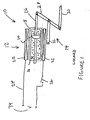
- FIGURE 1 is a schematic diagram of a vehicle locking mechanism according to one embodiment of the invention.
- FIGURE 2 illustrates the tensile operation of the mechanism of Figure 1 when in a locked condition; and
- FIGURE 3 illustrates the mechanism of Figure 1 in an unlocked condition.
- Referring to Figure 1, there is shown generally at 10 a locking mechanism comprising a
motion control device 12 and alinkage arrangement 14 mounted in a vehicle door (not shown) so as to lock the door when in a closed position relative to an associated vehicle. - The
motion control device 12 comprises acylinder 18 containing a magneto-rheological (hereinafter referred to as MR)fluid 16. A perforatedpiston 20 is securely mounted on aram 26, the piston being axially slidable withincylinder 16. - In this embodiment, the
piston 20 is shaped such that movement from right to left in the Figures requires less force than movement left to right. This may act to damp the return of a door handle to which the mechanism is attached. In other embodiments, the piston design may be altered to reverse this, or to make the required force equal in both directions in accordance with the particular requirement of the mechanism or components with which the mechanism interacts. - The
cylinder 18 is at least partially surrounded by anelectromagnet 22 connected by acircuit 24 toelectrical power source 34 such as the vehicle battery. Aswitch 26 is provided to enable the circuit to be energised, such that when the switch is closed, a magnetic field is induced in the MR fluid by theelectromagnet 22. Magnetic shielding (not shown) is preferably provided to ensure that theMR fluid 16 is not influenced by external magnetic fields. - Magneto-rheological fluids are suspensions of small magnetisable particles in a liquid such as oil. MR fluids are normally free flowing and have a viscosity similar to that of motor oil. However, once a magnetic field is applied across the fluid, the fluid consistency becomes almost instantly more viscous. The increase in viscosity is proportional to the magnitude of the magnetic field applied. Electro-rheological fluids (hereinafter ER fluids) function in a similar manner upon application of a potential difference across the fluid.
- In this embodiment, the
linkage 14 comprises aninput arm 30 which in this embodiment is connected to an internal and/or external door handle (not shown) of the associated vehicle door, and anoutput member 32 connected to an input of a latching mechanism (not shown) of the vehicle. Ram 26 andinput arm 30 are pivotally interconnected by a connecting arm 28 at the distal ends ofram 26,arm 30 and connecting arm 28.Output arm 32 is pivotally connected to the connecting arm 28 at a position intermediate the ends of connecting arm 28. - When the locking mechanism is in a first, locked state, the potential difference is not applied to
electromagnet 22. Therefore, the MR fluid is this first state has a low viscosity such that the fluid may pass through the perforations in the piston andpiston 20 may move alongcylinder 18 in a relatively unhindered manner. - Thus, when
arm 30 is caused to moved in a direction X shown in Figure 2 by operation of the handle connected thereto, the force required to displace thepiston 20 is lower than the force required to causearm 32 to unlatch the latching mechanism. Movement ofarm 30 in a direction X merely causes a corresponding movement ofpiston 20 andram 26 in the direction Y, with substantially no movement ofarm 32, resulting in the latching mechanism remaining latched. - Referring now to Figure 3, it can be seen that
switch 26 is now closed, thus energising theelectromagnet 22. This causes the viscosity ofMR fluid 16 to increase so that movement ofarm 30 by the door handle in the direction X in turn causesarm 32 to move in a direction Z because in this second unlocked state, the force required to unlatch the latching system is lower than the force required to displace thepiston 20. - It is therefore apparent that the locking mechanism of the present invention requires fewer moving parts than prior art devices, and is particularly suited to use with passive/keyless entry systems that are by their very nature electrically controlled. For this reason, the locking mechanism of the present invention may be easily integrated into such a passive entry system by causing
switch 26 to be under its control. If the passive entry system determines that a particular person should be permitted entry to thevehicle switch 26 is closed. Otherwise,switch 26 remains open and the door remains locked. A particular advantage of this arrangement is that the locking mechanism consumes no power when in the locked state. - Vehicle door latches, typically have a number of operating modes. For a latch having an override unlocking function, these may include locked (when pulling on an outside door handle will not release the latch but pulling on an inside handle may override the locked state, superlocked (when pulling on both the inside and outside handle will not release the door) and child safety (in which the latch can be unlocked by the inside door handle but not released). To provide these modes, latches may comprise separate mechanisms of the present invention in the transmission path from the inside and outside door handles. The mechanisms may be individually controlled by a controller to provide the above described modes as appropriate.
- It should be understood that numerous changes may be made within the scope of the present invention as defined by the appended claims. In alternative embodiments, an ER fluid may be used rather than an MR fluid. Furthermore, appropriate alterations may be made to the
electrical circuit 24 and/or the design of the cylinder and piston so that the mechanism may be adjusted to take into account changes in the viscosity of the fluid used and in the unlatching load of a particular latch mechanism. In particular, the resistance displacement of the piston may be adjusted to provide differing resistance in either direction of travel as required for the overall function of the mechanism. The mechanism may be fitted to a door surround portion of a vehicle rather than the door itself. It should be apparent that the mechanism may have applications in other fields such as locking mechanisms in buildings.
Claims (11)
- A door latch comprising a locking mechanism (10) for selectively locking and unlocking the door latch, the mechanism comprising an input (30) for operable connection to a door handle, a rheological fluid (16) held within a cylinder (18), and an output (32) operably connected to a release mechanism of the latch, the fluid acting so as to in a first state prevent actuation of the output upon actuation of the input and in a second state permit such actuation, characterised in that a piston (20) is slidably disposed in the cylinder and is connected to the input and output via a linkage (14), the linkage including an arm (28) pivotally interconnecting a ram connected to the piston and the input and output of the mechanism.
- A door latch according to Claim 1 wherein in the first state the fluid has a first viscosity and in the second state the fluid has a second viscosity, the second viscosity being higher than the first.
- A door latch according to any preceding Claim wherein the fluid is a magneto-rheological fluid.
- A door latch according to Claim 3 wherein a magnetic field is applied across the fluid in its second state and substantially no magnetic field is applied across the fluid in its first state.
- A door latch according to Claims 1 or 2 wherein the fluid is an electro-rheological fluid.
- A door latch according to Claim 5 wherein a potential difference is applied across the fluid in its second state and substantially no potential difference is applied across the fluid in its first state.
- A door latch according to Claim 1 wherein the piston is shaped such that resistance to movement of the piston in a first direction is greater than resistance to movement in a second direction.
- A door latch according to any preceding Claim wherein the input is connected to a handle associated with a door.
- A door latch according to any preceding Claim wherein the lock mechanism is locked when the fluid is in its first state and unlocked when the fluid is in its second state.
- A door latch according to any preceding claim wherein the piston is perforated.
- A keyless entry system incorporating a door latch comprising a locking mechanism according to any preceding Claim.
Applications Claiming Priority (2)
| Application Number | Priority Date | Filing Date | Title |
|---|---|---|---|
| GB0113542 | 2001-06-05 | ||
| GBGB0113542.5A GB0113542D0 (en) | 2001-06-05 | 2001-06-05 | A mechanism |
Publications (2)
| Publication Number | Publication Date |
|---|---|
| EP1264992A1 EP1264992A1 (en) | 2002-12-11 |
| EP1264992B1 true EP1264992B1 (en) | 2006-09-27 |
Family
ID=9915851
Family Applications (1)
| Application Number | Title | Priority Date | Filing Date |
|---|---|---|---|
| EP02253319A Expired - Lifetime EP1264992B1 (en) | 2001-06-05 | 2002-05-13 | A rheological fluid actuator for a lock |
Country Status (4)
| Country | Link |
|---|---|
| US (1) | US7097212B2 (en) |
| EP (1) | EP1264992B1 (en) |
| DE (1) | DE60214930T2 (en) |
| GB (1) | GB0113542D0 (en) |
Families Citing this family (23)
| Publication number | Priority date | Publication date | Assignee | Title |
|---|---|---|---|---|
| DE102004023926B3 (en) * | 2004-05-12 | 2005-08-11 | Dorma Gmbh + Co. Kg | Sliding door system for glass doors has a lock with a rotational body connected to a driven plate and having a coupling part for locking with a locking bolt positioned in a door frame |
| US7331616B2 (en) * | 2004-07-15 | 2008-02-19 | General Motors Corporation | Hood latch assemblies utilizing active materials and methods of use |
| DE102004061687A1 (en) * | 2004-12-22 | 2006-07-06 | Daimlerchrysler Ag | Vehicle door with a braking function |
| DE102004061686A1 (en) * | 2004-12-22 | 2006-07-06 | Daimlerchrysler Ag | Vehicle door with variable locking function |
| AT502365B1 (en) * | 2005-08-23 | 2009-05-15 | Evva Werke | RELEASE AND LOCKING ELEMENT |
| US7501595B2 (en) * | 2005-10-06 | 2009-03-10 | Strattec Security Corporation | Self-compensating motion detector |
| EP1835097B1 (en) * | 2006-03-16 | 2008-09-03 | CRF Societa'Consortile per Azioni | Manual actuating system assisted by a shape memory actuator |
| US8066567B2 (en) * | 2006-08-25 | 2011-11-29 | Deere & Company | Joystick with control dampening and detent using electrorheologic cylinder |
| US8104823B2 (en) * | 2007-06-15 | 2012-01-31 | Ford Global Technologies | Automotive door with hydraulically locking repositionable immobilizer |
| US8196975B2 (en) * | 2007-08-14 | 2012-06-12 | Magna Closures Inc | Safety device for vehicle door latch systems |
| GB2464311B (en) * | 2008-10-13 | 2012-08-15 | Huf Huelsbeck & Fuerst Gmbh & Co Kg | Latch mechanism with inertia event sensor |
| US8016026B2 (en) * | 2008-11-25 | 2011-09-13 | Baker Hughes Incorporated | Actuator for downhole tools |
| WO2010062282A1 (en) * | 2008-11-28 | 2010-06-03 | Utc Fire & Security Corporation | Semi-active electrorheological fluid clutch for electronic door lock |
| CN201318085Y (en) * | 2008-12-22 | 2009-09-30 | 罗志刚 | Locking structure for bathtub door |
| US8123262B2 (en) * | 2008-12-24 | 2012-02-28 | GM Global Technology Operations LLC | Damping assembly for reducing vibrations in a latch for a vehicle door |
| DE102011120188B4 (en) * | 2011-12-05 | 2013-08-29 | Audi Ag | Emergency release device for a vehicle boot |
| US9004551B2 (en) * | 2012-08-13 | 2015-04-14 | GM Global Technology Operations LLC | Latchable or lockable device |
| US9605450B2 (en) | 2014-05-20 | 2017-03-28 | Ford Global Technologies, Llc | Vehicle door closure system including speed-based latch release |
| US10072448B2 (en) | 2014-05-29 | 2018-09-11 | Ford Global Technologies, Llc | Vehicle door handle |
| US10240370B2 (en) | 2015-04-03 | 2019-03-26 | Ford Global Technologies, Llc | Vehicle door latch with release linkage bypass device |
| DE102015119505B4 (en) * | 2015-07-21 | 2022-12-08 | Inventus Engineering Gmbh | Door component with a controllable damper device |
| US10385592B2 (en) | 2016-08-15 | 2019-08-20 | Ford Global Technologies, Llc | Latch internal mechanism |
| CN120895195B (en) * | 2025-09-09 | 2026-05-29 | 深圳市瑞意博医疗设备有限公司 | Comprehensive collaborative management system and method for taking and supplementing refined drugs |
Family Cites Families (56)
| Publication number | Priority date | Publication date | Assignee | Title |
|---|---|---|---|---|
| US709607A (en) * | 1897-03-16 | 1902-09-23 | Henry Joseph Podlesak | Electrical releaser for fire-doors, &c. |
| US971423A (en) * | 1910-05-06 | 1910-09-27 | Frank Walters | Lock. |
| US1057608A (en) * | 1910-08-29 | 1913-04-01 | Nat Clock & Electric Mfg Co | Automatic electric release for fire-doors. |
| FR430732A (en) * | 1911-04-28 | 1911-10-23 | Clovis Hottelart | Machine for defibrating and carding ropes, cables, wrapping cloths, fabrics or any other textile material |
| US1970807A (en) * | 1933-09-03 | 1934-08-21 | John G Lovell | Electromagnetic control system |
| US2070103A (en) * | 1935-06-26 | 1937-02-09 | Wiebe Arthur | Lock operating means for automobiles |
| US2505401A (en) * | 1947-04-03 | 1950-04-25 | Empire Electric Brake Company | Door locking system |
| US2934930A (en) * | 1958-07-31 | 1960-05-03 | Gen Motors Corp | Coincidental door locking system |
| US3090644A (en) * | 1960-10-19 | 1963-05-21 | Daimler Benz Ag | Door lock |
| US3113447A (en) * | 1961-01-03 | 1963-12-10 | Trico Products Corp | Remotely actuated trunk lock arrangement for a motor vehicle |
| US3593816A (en) * | 1968-12-30 | 1971-07-20 | Aisin Seiki | Automotive door lock |
| US3602019A (en) * | 1969-07-01 | 1971-08-31 | Aisin Seiki | Door-locking arrangement for automotive vehicle |
| US3580623A (en) * | 1969-07-31 | 1971-05-25 | Gen Motors Corp | Latch mechanism |
| US3596484A (en) * | 1969-07-31 | 1971-08-03 | Gen Motors Corp | Closure latch |
| US3664698A (en) * | 1970-04-02 | 1972-05-23 | Prod Design & Mfg | Electric actuating mechanism |
| US3726368A (en) * | 1970-10-30 | 1973-04-10 | P Taylor | Fluid amplified liquid spring shocks and/or shock absorbers |
| US4033616A (en) * | 1972-08-28 | 1977-07-05 | Keystone Industries, Inc. | Automotive vehicle door retarding and closing mechanism |
| US3917327A (en) * | 1974-02-05 | 1975-11-04 | Micro Devices Corp | Thermally actuated device and door latch means utilizing the same or the like |
| US3971581A (en) * | 1974-06-17 | 1976-07-27 | Montgomery Tom C | Variable magnetic lock |
| US4196924A (en) * | 1977-07-28 | 1980-04-08 | Ohta Company Limited | Automatic door closing device |
| US4169616A (en) * | 1977-09-26 | 1979-10-02 | C. Hager & Sons Hinge Manufacturing Company | Valve and cylinder-actuated lock controlled thereby |
| FR2501765A1 (en) * | 1981-03-10 | 1982-09-17 | Mecanismes Comp Ind De | LOCK, ESPECIALLY FOR A MOTOR VEHICLE DOOR |
| US4886307A (en) * | 1987-04-01 | 1989-12-12 | Ewald Witte & Co. | Lock, particularly for trunk or engine compartments of automotive vehicles, doors or the like |
| DE3802107C1 (en) * | 1988-01-26 | 1989-05-03 | Daimler-Benz Aktiengesellschaft, 7000 Stuttgart, De | |
| US4913475A (en) * | 1988-04-18 | 1990-04-03 | Phelps-Tointon, Inc. | Security lock mechanism |
| AT395391B (en) | 1989-10-20 | 1992-12-10 | Vaillant Gmbh | LOCKING DEVICE FOR THE CORE OF A DIE CAST |
| US5074389A (en) * | 1990-01-25 | 1991-12-24 | Bobcat Engineering Corporation | Peripherally valved, temperature-compensated shock absorber |
| US4993747A (en) | 1990-03-12 | 1991-02-19 | General Motors Corporation | Electro-rheological belt load anchorage mechanism |
| US5177988A (en) * | 1991-07-31 | 1993-01-12 | Bushnell Raymond B | Security lock mechanism incorporating hydraulic dead locking |
| DE4205269C1 (en) * | 1992-02-21 | 1993-05-06 | Mercedes-Benz Aktiengesellschaft, 7000 Stuttgart, De | |
| US5284330A (en) * | 1992-06-18 | 1994-02-08 | Lord Corporation | Magnetorheological fluid devices |
| DE4224132C2 (en) * | 1992-07-22 | 2002-11-14 | Stabilus Gmbh | Door locking system |
| US5263347A (en) * | 1992-09-21 | 1993-11-23 | Allbaugh Mark E | Remote control deadlock bolt for cars |
| US5263751A (en) * | 1992-11-16 | 1993-11-23 | General Motors Corporation | Door latch actuator |
| JPH07225869A (en) * | 1994-02-10 | 1995-08-22 | Fuji Electric Co Ltd | Door lock device for vending machines |
| US5868445A (en) * | 1995-11-02 | 1999-02-09 | Kaufman; Eli | Magnetic slide lock assembly |
| US5636536A (en) * | 1995-12-08 | 1997-06-10 | Kinnucan; James A. | Remotely operable security deadbolt lock device with anti-theft manually operable release |
| DE19548562B4 (en) * | 1995-12-23 | 2004-12-16 | Siemens Ag | Device for unlocking the doors of a motor vehicle |
| EP0808977B1 (en) * | 1996-05-21 | 2000-08-16 | Robert Bosch Gmbh | Method for controlling an electrically actuated vehicle door lock |
| US5730028A (en) * | 1996-07-22 | 1998-03-24 | United Technologies Automotive, Inc. | Linkage for a power liftgate lock system |
| DE19717691A1 (en) * | 1997-04-26 | 1998-10-29 | Schenck Ag Carl | Actuator, esp. of linear or rotational type |
| DE19754167B4 (en) * | 1997-12-06 | 2008-08-21 | Volkswagen Ag | Device for stepless locking of a component pivotable about an axis |
| DE19801752C1 (en) * | 1998-01-20 | 1999-05-12 | Dorma Gmbh & Co Kg | Locking device for emergency exit doors |
| US5984385A (en) * | 1998-05-12 | 1999-11-16 | Trw Inc. | Active ERM damper for spacecraft telescoping structures |
| US6027148A (en) * | 1998-06-12 | 2000-02-22 | Shoemaker; Rodney | Security device for a movable closure and method therefor |
| US6343494B2 (en) * | 1998-08-11 | 2002-02-05 | Mannesmann Vdo Ag | Locking device |
| DE19841729B4 (en) * | 1998-09-12 | 2006-07-06 | Siemens Ag | Handle arrangement for a movable body part |
| DE19910782C2 (en) * | 1999-03-11 | 2001-01-25 | Stabilus Gmbh | Door hinge with a blockage due to a field force |
| DE19924685B4 (en) * | 1999-05-28 | 2016-10-27 | Fludicon Gmbh | closing mechanism |
| US6318521B1 (en) * | 1999-06-16 | 2001-11-20 | Bridgestone/Firestone, Inc. | Externally guided ER damper |
| DE19939063A1 (en) * | 1999-08-18 | 2001-02-22 | Volkswagen Ag | Actuating opening and closing functions in motor vehicles involves pre-actuating locking system with long range transponder, carrying out only on approaching with short range transponder |
| US6514001B1 (en) * | 1999-12-29 | 2003-02-04 | Daimlerchrysler Corporation | Variable length shaft and method for making the same |
| US6481659B1 (en) * | 2000-04-07 | 2002-11-19 | Delphi Technologies, Inc. | Variable load limiting restraint retractor |
| US6437687B2 (en) * | 2000-05-31 | 2002-08-20 | Douglas Autotech Corp. | Alarm mechanism |
| US6279702B1 (en) * | 2001-01-05 | 2001-08-28 | Mando Corporation | Shock absorber using a hydraulic fluid and a magnetorheological fluid |
| DE10114583C1 (en) * | 2001-03-24 | 2002-12-05 | Huf Huelsbeck & Fuerst Gmbh | Outside door handle, in particular for vehicles |
-
2001
- 2001-06-05 GB GBGB0113542.5A patent/GB0113542D0/en not_active Ceased
-
2002
- 2002-05-13 EP EP02253319A patent/EP1264992B1/en not_active Expired - Lifetime
- 2002-05-13 DE DE60214930T patent/DE60214930T2/en not_active Expired - Fee Related
- 2002-05-30 US US10/158,567 patent/US7097212B2/en not_active Expired - Fee Related
Also Published As
| Publication number | Publication date |
|---|---|
| DE60214930T2 (en) | 2007-09-06 |
| EP1264992A1 (en) | 2002-12-11 |
| DE60214930D1 (en) | 2006-11-09 |
| GB0113542D0 (en) | 2001-07-25 |
| US20030006617A1 (en) | 2003-01-09 |
| US7097212B2 (en) | 2006-08-29 |
Similar Documents
| Publication | Publication Date | Title |
|---|---|---|
| US7097212B2 (en) | Mechanism | |
| US6879058B2 (en) | Door latch arrangement | |
| EP1347132B1 (en) | Vehicle door system comprising lock indicator | |
| US6116664A (en) | Lock, in particular for car doors or the like | |
| US5653484A (en) | Motor-vehicle door latch | |
| US6474120B1 (en) | Bolt assembly | |
| EP1518982B1 (en) | Latch arrangements for automotive doors or other closures | |
| RU2628977C2 (en) | Door lock of vehicle | |
| EP3805490B1 (en) | Electrical striker unit | |
| US6519987B1 (en) | Motor vehicle door lock system with passive entry function and high-speed unlocking | |
| WO2014203930A1 (en) | Vehicle door handle | |
| US20030177974A1 (en) | Lock Indicator | |
| US6431617B1 (en) | Door mechanism | |
| IT202000012172A1 (en) | DEVICE FOR CLOSING THE DOOR OF AN APPLIANCE | |
| EP1747335A1 (en) | Divided spindle | |
| GB2267928A (en) | Vehicle locking systems. | |
| DE10151022A1 (en) | Motor vehicle door lock with separate locking unit and control unit | |
| US5683125A (en) | Single-handle inside actuator for motor-vehicle door latch | |
| US5441317A (en) | Superlock feature for an automotive door locking actuator | |
| EP1290301B1 (en) | Latch apparatus and method | |
| US20150115617A1 (en) | Apparatus and method for wirelessly transmitting data from a vehicle latch | |
| CN101550782A (en) | Lock with a selector element for changing the operational properties of the lock | |
| EP1281826B1 (en) | Latch arrangement | |
| EP4139546A1 (en) | Bumping preventing arrangement for lock device, lock device and method | |
| US312575A (en) | Door-latch |
Legal Events
| Date | Code | Title | Description |
|---|---|---|---|
| PUAI | Public reference made under article 153(3) epc to a published international application that has entered the european phase |
Free format text: ORIGINAL CODE: 0009012 |
|
| AK | Designated contracting states |
Kind code of ref document: A1 Designated state(s): AT BE CH CY DE DK ES FI FR GB GR IE IT LI LU MC NL PT SE TR |
|
| AX | Request for extension of the european patent |
Free format text: AL;LT;LV;MK;RO;SI |
|
| 17P | Request for examination filed |
Effective date: 20030522 |
|
| AKX | Designation fees paid |
Designated state(s): DE FR GB |
|
| 17Q | First examination report despatched |
Effective date: 20040510 |
|
| GRAP | Despatch of communication of intention to grant a patent |
Free format text: ORIGINAL CODE: EPIDOSNIGR1 |
|
| RIN1 | Information on inventor provided before grant (corrected) |
Inventor name: DIDIER, JEAN Inventor name: DRYSDALE, STEPHEN Inventor name: EMSON, JOHN Inventor name: DIXON, ALAN Inventor name: WILLATS, ROBIN Inventor name: KALSI, GURBINDER Inventor name: FISHER, SIDNEY Inventor name: SPURR, NIGEL |
|
| GRAS | Grant fee paid |
Free format text: ORIGINAL CODE: EPIDOSNIGR3 |
|
| GRAA | (expected) grant |
Free format text: ORIGINAL CODE: 0009210 |
|
| AK | Designated contracting states |
Kind code of ref document: B1 Designated state(s): DE FR GB |
|
| REG | Reference to a national code |
Ref country code: GB Ref legal event code: FG4D |
|
| REF | Corresponds to: |
Ref document number: 60214930 Country of ref document: DE Date of ref document: 20061109 Kind code of ref document: P |
|
| ET | Fr: translation filed | ||
| RAP2 | Party data changed (patent owner data changed or rights of a patent transferred) |
Owner name: MERITOR TECHNOLOGY, INC. |
|
| PLBE | No opposition filed within time limit |
Free format text: ORIGINAL CODE: 0009261 |
|
| STAA | Information on the status of an ep patent application or granted ep patent |
Free format text: STATUS: NO OPPOSITION FILED WITHIN TIME LIMIT |
|
| 26N | No opposition filed |
Effective date: 20070628 |
|
| GBPC | Gb: european patent ceased through non-payment of renewal fee |
Effective date: 20070513 |
|
| REG | Reference to a national code |
Ref country code: FR Ref legal event code: ST Effective date: 20080131 |
|
| PG25 | Lapsed in a contracting state [announced via postgrant information from national office to epo] |
Ref country code: DE Free format text: LAPSE BECAUSE OF NON-PAYMENT OF DUE FEES Effective date: 20071201 |
|
| PG25 | Lapsed in a contracting state [announced via postgrant information from national office to epo] |
Ref country code: GB Free format text: LAPSE BECAUSE OF NON-PAYMENT OF DUE FEES Effective date: 20070513 |
|
| PG25 | Lapsed in a contracting state [announced via postgrant information from national office to epo] |
Ref country code: FR Free format text: LAPSE BECAUSE OF NON-PAYMENT OF DUE FEES Effective date: 20070531 |
|
| REG | Reference to a national code |
Ref country code: GB Ref legal event code: 732E |