EP1264983A2 - Internal combustion engine fuel injector - Google Patents
Internal combustion engine fuel injector Download PDFInfo
- Publication number
- EP1264983A2 EP1264983A2 EP02012502A EP02012502A EP1264983A2 EP 1264983 A2 EP1264983 A2 EP 1264983A2 EP 02012502 A EP02012502 A EP 02012502A EP 02012502 A EP02012502 A EP 02012502A EP 1264983 A2 EP1264983 A2 EP 1264983A2
- Authority
- EP
- European Patent Office
- Prior art keywords
- injector
- shutter
- axis
- head
- pin
- Prior art date
- Legal status (The legal status is an assumption and is not a legal conclusion. Google has not performed a legal analysis and makes no representation as to the accuracy of the status listed.)
- Granted
Links
Images


Classifications
-
- F—MECHANICAL ENGINEERING; LIGHTING; HEATING; WEAPONS; BLASTING
- F02—COMBUSTION ENGINES; HOT-GAS OR COMBUSTION-PRODUCT ENGINE PLANTS
- F02M—SUPPLYING COMBUSTION ENGINES IN GENERAL WITH COMBUSTIBLE MIXTURES OR CONSTITUENTS THEREOF
- F02M61/00—Fuel-injectors not provided for in groups F02M39/00 - F02M57/00 or F02M67/00
- F02M61/04—Fuel-injectors not provided for in groups F02M39/00 - F02M57/00 or F02M67/00 having valves, e.g. having a plurality of valves in series
- F02M61/10—Other injectors with elongated valve bodies, i.e. of needle-valve type
- F02M61/12—Other injectors with elongated valve bodies, i.e. of needle-valve type characterised by the provision of guiding or centring means for valve bodies
-
- F—MECHANICAL ENGINEERING; LIGHTING; HEATING; WEAPONS; BLASTING
- F02—COMBUSTION ENGINES; HOT-GAS OR COMBUSTION-PRODUCT ENGINE PLANTS
- F02M—SUPPLYING COMBUSTION ENGINES IN GENERAL WITH COMBUSTIBLE MIXTURES OR CONSTITUENTS THEREOF
- F02M47/00—Fuel-injection apparatus operated cyclically with fuel-injection valves actuated by fluid pressure
- F02M47/02—Fuel-injection apparatus operated cyclically with fuel-injection valves actuated by fluid pressure of accumulator-injector type, i.e. having fuel pressure of accumulator tending to open, and fuel pressure in other chamber tending to close, injection valves and having means for periodically releasing that closing pressure
- F02M47/027—Electrically actuated valves draining the chamber to release the closing pressure
-
- F—MECHANICAL ENGINEERING; LIGHTING; HEATING; WEAPONS; BLASTING
- F02—COMBUSTION ENGINES; HOT-GAS OR COMBUSTION-PRODUCT ENGINE PLANTS
- F02M—SUPPLYING COMBUSTION ENGINES IN GENERAL WITH COMBUSTIBLE MIXTURES OR CONSTITUENTS THEREOF
- F02M61/00—Fuel-injectors not provided for in groups F02M39/00 - F02M57/00 or F02M67/00
- F02M61/04—Fuel-injectors not provided for in groups F02M39/00 - F02M57/00 or F02M67/00 having valves, e.g. having a plurality of valves in series
- F02M61/10—Other injectors with elongated valve bodies, i.e. of needle-valve type
-
- F—MECHANICAL ENGINEERING; LIGHTING; HEATING; WEAPONS; BLASTING
- F02—COMBUSTION ENGINES; HOT-GAS OR COMBUSTION-PRODUCT ENGINE PLANTS
- F02M—SUPPLYING COMBUSTION ENGINES IN GENERAL WITH COMBUSTIBLE MIXTURES OR CONSTITUENTS THEREOF
- F02M61/00—Fuel-injectors not provided for in groups F02M39/00 - F02M57/00 or F02M67/00
- F02M61/16—Details not provided for in, or of interest apart from, the apparatus of groups F02M61/02 - F02M61/14
- F02M61/168—Assembling; Disassembling; Manufacturing; Adjusting
-
- F—MECHANICAL ENGINEERING; LIGHTING; HEATING; WEAPONS; BLASTING
- F02—COMBUSTION ENGINES; HOT-GAS OR COMBUSTION-PRODUCT ENGINE PLANTS
- F02M—SUPPLYING COMBUSTION ENGINES IN GENERAL WITH COMBUSTIBLE MIXTURES OR CONSTITUENTS THEREOF
- F02M2547/00—Special features for fuel-injection valves actuated by fluid pressure
- F02M2547/003—Valve inserts containing control chamber and valve piston
-
- F—MECHANICAL ENGINEERING; LIGHTING; HEATING; WEAPONS; BLASTING
- F02—COMBUSTION ENGINES; HOT-GAS OR COMBUSTION-PRODUCT ENGINE PLANTS
- F02M—SUPPLYING COMBUSTION ENGINES IN GENERAL WITH COMBUSTIBLE MIXTURES OR CONSTITUENTS THEREOF
- F02M63/00—Other fuel-injection apparatus having pertinent characteristics not provided for in groups F02M39/00 - F02M57/00 or F02M67/00; Details, component parts, or accessories of fuel-injection apparatus, not provided for in, or of interest apart from, the apparatus of groups F02M39/00 - F02M61/00 or F02M67/00; Combination of fuel pump with other devices, e.g. lubricating oil pump
- F02M63/0012—Valves
- F02M63/0014—Valves characterised by the valve actuating means
- F02M63/0015—Valves characterised by the valve actuating means electrical, e.g. using solenoid
- F02M63/0017—Valves characterised by the valve actuating means electrical, e.g. using solenoid using electromagnetic operating means
Definitions
- Number 1 in Figure 1 indicates a fuel injector for an internal combustion engine, in particular a diesel engine (not shown).
- Injector 1 comprises a hollow outer structure or casing 2 extending along an axis 3, and having a lateral inlet 5 for connection to a pump forming part of a fuel supply system (not shown), and an end nozzle 7 communicating with inlet 5 to inject fuel into a relative cylinder of the engine.
- Casing 2 comprises an intermediate axial portion 8, and two opposite end portions 9, 10.
- Portion 9 is located on the opposite side to nozzle 7, and houses a known electromagnetic metering valve 12 (not described in detail) having an outlet 13 for recirculating back to the supply system tank (not shown) the portion of fuel "consumed” by valve 12, and the portion of fuel leaking through the internal components of injector 1, and which is fed to valve 12 along an inner conduit 14.
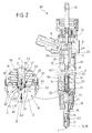
- Portion 21 is connected to portion 31 by a connecting device 35 for transmitting from rod 23 to pin 16 a resultant of forces A directed solely along axis 19.
- Device 35 comprises a cavity 36 formed, coaxially with axis 19, in portion 21 and defined by a conical surface 37; and a spherical spacer body 39 interposed between pin 16 and rod 23, and engaging cavity 36.
- Body 39 is defined by a spherical surface 40 resting, on one side, on the flat end of portion 31, at a point of contact 42 along axis 19, and, on the other side, on conical surface 37, along a circular line of contact 43 (shown by a dash line in Figures 1, 2 and 3).
Landscapes
- Engineering & Computer Science (AREA)
- Chemical & Material Sciences (AREA)
- Combustion & Propulsion (AREA)
- Mechanical Engineering (AREA)
- General Engineering & Computer Science (AREA)
- Physics & Mathematics (AREA)
- Fluid Mechanics (AREA)
- Manufacturing & Machinery (AREA)
- Fuel-Injection Apparatus (AREA)
Abstract
Description
Claims (15)
- A fuel injector (1; 51) for an internal combustion engine; the injector (1; 51) comprising a casing (2) defining a nozzle (7) for injecting fuel into said engine; a shutter (16) having an axis (19) and housed in axially sliding manner inside said casing (2) to open and close said nozzle (7); control means (23) for pushing said shutter (16) towards said nozzle (7) to close the nozzle (7); and connecting means (35; 55) for connecting said shutter (16) to said control means (23); characterized in that said connecting means (35; 55) comprise an axial seat (36) carried by one of said shutter (16) and said control means (23); and a head (39; 59; 69) interposed between said axial seat (36) and the other of said shutter (16) and said control means (23), and engaging said axial seat (36) so as to transmit to said shutter (16) a resultant of forces (A) directed solely along said axis (19) of said shutter (16).
- An injector as claimed in Claim 1, characterized in that said axial seat (36) and said head (39; 59; 69) interact with each other along an annular line of contact (43; 73) symmetrical with respect to said axis (19).
- An injector as claimed in Claim 2, characterized in that said annular line of contact (43; 73) is a circular line.
- An injector as claimed in Claim 3, characterized in that said axial seat (36) is defined by a conical surface (37) coaxial with said axis (19).
- An injector as claimed in Claim 3 or 4, characterized in that said head (39; 59) is at least partly defined by a spherical surface (40; 60) engaging said axial seat (36).
- An injector as claimed in Claim 4, characterized in that said head (69) comprises a conical portion (69) engaging said axial seat (36).
- An injector as claimed in any one of Claims 2 to 6, characterized in that said annular line of contact (43; 73) defines part of an annular area of contact.
- An injector as claimed in any one of the foregoing Claims, characterized in that said axial seat (36) is formed in said shutter (16).
- An injector as claimed in Claim 8, characterized in that said control means (23) comprise a control rod (23) extending along said axis (19); said head (39; 59; 69) being carried by said control rod (23).
- An injector as claimed in Claim 9, characterized in that said head (39) is defined by a spherical body (39) resting on said control rod (23) at a point of contact (42) lying along said axis (19).
- An injector as claimed in Claim 9, characterized in that said head (59; 69) defines the end of said control rod (23).
- An injector as claimed in Claim 11, characterized by comprising a guide seat (26) for guiding said control rod (23); said control rod (23) comprising an end portion (28) engaging said guide seat (26) in axially sliding manner, and a weakened intermediate portion (63) allowing said head (59; 69) to flex with respect to the end portion (28) in directions crosswise to said axis (19).
- An injector as claimed in Claim 12, characterized in that said weakened intermediate portion (63) has a circumferential groove (61).
- An injector as claimed in any one of the foregoing Claims, characterized by comprising elastic means (22; 64) interposed axially between said shutter (16) and said casing (2).
- An injector as claimed in Claim 14, characterized in that said elastic means (64) rest axially directly on said shutter (16).
Applications Claiming Priority (2)
| Application Number | Priority Date | Filing Date | Title |
|---|---|---|---|
| ITTO20010539 | 2001-06-05 | ||
| IT2001TO000539A ITTO20010539A1 (en) | 2001-06-05 | 2001-06-05 | FUEL INJECTOR FOR AN INTERNAL COMBUSTION ENGINE. |
Publications (3)
| Publication Number | Publication Date |
|---|---|
| EP1264983A2 true EP1264983A2 (en) | 2002-12-11 |
| EP1264983A3 EP1264983A3 (en) | 2003-04-09 |
| EP1264983B1 EP1264983B1 (en) | 2004-10-27 |
Family
ID=11458932
Family Applications (1)
| Application Number | Title | Priority Date | Filing Date |
|---|---|---|---|
| EP02012502A Expired - Lifetime EP1264983B1 (en) | 2001-06-05 | 2002-06-04 | Internal combustion engine fuel injector |
Country Status (6)
| Country | Link |
|---|---|
| US (1) | US7044109B2 (en) |
| EP (1) | EP1264983B1 (en) |
| AT (1) | ATE280900T1 (en) |
| DE (1) | DE60201708T2 (en) |
| ES (1) | ES2229014T3 (en) |
| IT (1) | ITTO20010539A1 (en) |
Families Citing this family (3)
| Publication number | Priority date | Publication date | Assignee | Title |
|---|---|---|---|---|
| ES2277229T3 (en) * | 2004-06-30 | 2007-07-01 | C.R.F. Societa Consortile Per Azioni | SERVOVALVULA TO CONTROL THE FUEL INJECTOR OF AN INTERNAL COMBUSTION ENGINE. |
| JP2009197947A (en) * | 2008-02-22 | 2009-09-03 | Denso Corp | Solenoid valve and fuel injection valve |
| DE102012204659A1 (en) * | 2012-03-22 | 2013-09-26 | Man Diesel & Turbo Se | Injector for a fuel supply system of an internal combustion engine and fuel supply system |
Citations (5)
| Publication number | Priority date | Publication date | Assignee | Title |
|---|---|---|---|---|
| US3680782A (en) * | 1969-10-24 | 1972-08-01 | Sopromi Soc Proc Modern Inject | Electromagnetic injectors |
| DE4427378A1 (en) * | 1994-08-03 | 1996-02-08 | Bosch Robert Gmbh & Co Kg | Solenoid valve-controlled injector for fuel injection into the combustion chamber of a diesel engine |
| US5685483A (en) * | 1994-06-06 | 1997-11-11 | Ganser-Hydromag | Fuel injection valve for internal combustion engines |
| WO2001038723A1 (en) * | 1999-11-19 | 2001-05-31 | Robert Bosch Gmbh | Fuel injection valve for internal combustion engines |
| FR2815383A1 (en) * | 2000-10-12 | 2002-04-19 | Siemens Ag | Injector device, for automotive vehicle internal combustion engine fuel injection system, has sealing between the injector needle and injector body |
Family Cites Families (6)
| Publication number | Priority date | Publication date | Assignee | Title |
|---|---|---|---|---|
| US4684067A (en) * | 1986-03-21 | 1987-08-04 | General Motors Corporation | Two-stage, hydraulic-assisted fuel injection nozzle |
| DE19619523A1 (en) * | 1996-05-15 | 1997-11-20 | Bosch Gmbh Robert | Fuel injector for high pressure injection |
| DE19738397A1 (en) * | 1997-09-03 | 1999-03-18 | Bosch Gmbh Robert | Fuel injection system for an internal combustion engine |
| JP2000018119A (en) * | 1998-06-30 | 2000-01-18 | Isuzu Motors Ltd | Fuel injection system |
| GB9823028D0 (en) * | 1998-10-22 | 1998-12-16 | Lucas Ind Plc | Fuel injector |
| US6293254B1 (en) * | 2000-01-07 | 2001-09-25 | Cummins Engine Company, Inc. | Fuel injector with floating sleeve control chamber |
-
2001
- 2001-06-05 IT IT2001TO000539A patent/ITTO20010539A1/en unknown
-
2002
- 2002-06-04 DE DE60201708T patent/DE60201708T2/en not_active Expired - Lifetime
- 2002-06-04 EP EP02012502A patent/EP1264983B1/en not_active Expired - Lifetime
- 2002-06-04 AT AT02012502T patent/ATE280900T1/en not_active IP Right Cessation
- 2002-06-04 ES ES02012502T patent/ES2229014T3/en not_active Expired - Lifetime
- 2002-06-05 US US10/162,220 patent/US7044109B2/en not_active Expired - Lifetime
Patent Citations (5)
| Publication number | Priority date | Publication date | Assignee | Title |
|---|---|---|---|---|
| US3680782A (en) * | 1969-10-24 | 1972-08-01 | Sopromi Soc Proc Modern Inject | Electromagnetic injectors |
| US5685483A (en) * | 1994-06-06 | 1997-11-11 | Ganser-Hydromag | Fuel injection valve for internal combustion engines |
| DE4427378A1 (en) * | 1994-08-03 | 1996-02-08 | Bosch Robert Gmbh & Co Kg | Solenoid valve-controlled injector for fuel injection into the combustion chamber of a diesel engine |
| WO2001038723A1 (en) * | 1999-11-19 | 2001-05-31 | Robert Bosch Gmbh | Fuel injection valve for internal combustion engines |
| FR2815383A1 (en) * | 2000-10-12 | 2002-04-19 | Siemens Ag | Injector device, for automotive vehicle internal combustion engine fuel injection system, has sealing between the injector needle and injector body |
Also Published As
| Publication number | Publication date |
|---|---|
| US7044109B2 (en) | 2006-05-16 |
| ES2229014T3 (en) | 2005-04-16 |
| ITTO20010539A1 (en) | 2002-12-05 |
| EP1264983A3 (en) | 2003-04-09 |
| DE60201708D1 (en) | 2004-12-02 |
| US20030006297A1 (en) | 2003-01-09 |
| EP1264983B1 (en) | 2004-10-27 |
| ATE280900T1 (en) | 2004-11-15 |
| ITTO20010539A0 (en) | 2001-06-05 |
| DE60201708T2 (en) | 2005-10-06 |
Similar Documents
| Publication | Publication Date | Title |
|---|---|---|
| JP3881241B2 (en) | Fuel injector having a floating sleeve control chamber | |
| EP1612404B1 (en) | Internal combustion engine fuel injector | |
| EP0385397B1 (en) | Diesel engine electromagnetic fuel injector | |
| US20080257980A1 (en) | Fuel Injector | |
| EP2148082A1 (en) | Coupling arrangement for an injection valve and injection valve | |
| EP1136693B1 (en) | Plug pin for an internal combustion engine fuel injector nozzle | |
| JP2006504893A (en) | Injection valve | |
| US20030160202A1 (en) | Valve for controlling fluids | |
| US20060138255A1 (en) | Injector | |
| US6986474B2 (en) | Control module for an injector of an accumulator injection system | |
| EP1136692B1 (en) | Fuel injector with a control rod controlled by the fuel pressure in a control chamber | |
| US7044109B2 (en) | Internal combustion engine fuel injector | |
| KR20170012365A (en) | Nozzle assembly for a fuel injector, and fuel injector | |
| EP1284358B1 (en) | Internal combustion engine fuel injector and its manufacturing method | |
| US11591995B2 (en) | Fuel injector having valve seat orifice plate with valve seat and drain and re-pressurization orifices | |
| US7954475B2 (en) | Fuel injector | |
| EP1077326A2 (en) | Fuel injector | |
| US6216964B1 (en) | Fuel injector | |
| GB2364101A (en) | Pressure-controlled control part for common-rail fuel injectors | |
| US6568368B1 (en) | Common rail injector | |
| EP2282042B1 (en) | Valve assembly and injection valve | |
| CN108138734B (en) | Fluid injection device for internal combustion engine | |
| KR102071151B1 (en) | Injectors for combustion engines | |
| CN213175900U (en) | Common rail fuel injector | |
| US6575140B2 (en) | Fuel injection apparatus for internal combustion engines |
Legal Events
| Date | Code | Title | Description |
|---|---|---|---|
| PUAI | Public reference made under article 153(3) epc to a published international application that has entered the european phase |
Free format text: ORIGINAL CODE: 0009012 |
|
| AK | Designated contracting states |
Kind code of ref document: A2 Designated state(s): AT BE CH CY DE DK ES FI FR GB GR IE IT LI LU MC NL PT SE TR |
|
| AX | Request for extension of the european patent |
Free format text: AL;LT;LV;MK;RO;SI |
|
| PUAL | Search report despatched |
Free format text: ORIGINAL CODE: 0009013 |
|
| AK | Designated contracting states |
Kind code of ref document: A3 Designated state(s): AT BE CH CY DE DK ES FI FR GB GR IE IT LI LU MC NL PT SE TR |
|
| AX | Request for extension of the european patent |
Extension state: AL LT LV MK RO SI |
|
| RIC1 | Information provided on ipc code assigned before grant |
Ipc: 7F 02M 47/02 A Ipc: 7F 02M 61/20 B Ipc: 7F 02M 61/12 B |
|
| 17P | Request for examination filed |
Effective date: 20031008 |
|
| 17Q | First examination report despatched |
Effective date: 20031118 |
|
| AKX | Designation fees paid |
Designated state(s): AT BE CH CY DE DK ES FI FR GB GR IE IT LI LU MC NL PT SE TR |
|
| GRAP | Despatch of communication of intention to grant a patent |
Free format text: ORIGINAL CODE: EPIDOSNIGR1 |
|
| GRAS | Grant fee paid |
Free format text: ORIGINAL CODE: EPIDOSNIGR3 |
|
| GRAA | (expected) grant |
Free format text: ORIGINAL CODE: 0009210 |
|
| AK | Designated contracting states |
Kind code of ref document: B1 Designated state(s): AT BE CH CY DE DK ES FI FR GB GR IE IT LI LU MC NL PT SE TR |
|
| PG25 | Lapsed in a contracting state [announced via postgrant information from national office to epo] |
Ref country code: CH Free format text: LAPSE BECAUSE OF FAILURE TO SUBMIT A TRANSLATION OF THE DESCRIPTION OR TO PAY THE FEE WITHIN THE PRESCRIBED TIME-LIMIT Effective date: 20041027 Ref country code: LI Free format text: LAPSE BECAUSE OF FAILURE TO SUBMIT A TRANSLATION OF THE DESCRIPTION OR TO PAY THE FEE WITHIN THE PRESCRIBED TIME-LIMIT Effective date: 20041027 Ref country code: BE Free format text: LAPSE BECAUSE OF FAILURE TO SUBMIT A TRANSLATION OF THE DESCRIPTION OR TO PAY THE FEE WITHIN THE PRESCRIBED TIME-LIMIT Effective date: 20041027 Ref country code: FI Free format text: LAPSE BECAUSE OF FAILURE TO SUBMIT A TRANSLATION OF THE DESCRIPTION OR TO PAY THE FEE WITHIN THE PRESCRIBED TIME-LIMIT Effective date: 20041027 Ref country code: TR Free format text: LAPSE BECAUSE OF FAILURE TO SUBMIT A TRANSLATION OF THE DESCRIPTION OR TO PAY THE FEE WITHIN THE PRESCRIBED TIME-LIMIT Effective date: 20041027 Ref country code: NL Free format text: LAPSE BECAUSE OF FAILURE TO SUBMIT A TRANSLATION OF THE DESCRIPTION OR TO PAY THE FEE WITHIN THE PRESCRIBED TIME-LIMIT Effective date: 20041027 Ref country code: AT Free format text: LAPSE BECAUSE OF FAILURE TO SUBMIT A TRANSLATION OF THE DESCRIPTION OR TO PAY THE FEE WITHIN THE PRESCRIBED TIME-LIMIT Effective date: 20041027 |
|
| REG | Reference to a national code |
Ref country code: GB Ref legal event code: FG4D |
|
| REG | Reference to a national code |
Ref country code: CH Ref legal event code: EP |
|
| REG | Reference to a national code |
Ref country code: IE Ref legal event code: FG4D |
|
| REF | Corresponds to: |
Ref document number: 60201708 Country of ref document: DE Date of ref document: 20041202 Kind code of ref document: P |
|
| REG | Reference to a national code |
Ref country code: SE Ref legal event code: TRGR |
|
| PG25 | Lapsed in a contracting state [announced via postgrant information from national office to epo] |
Ref country code: DK Free format text: LAPSE BECAUSE OF FAILURE TO SUBMIT A TRANSLATION OF THE DESCRIPTION OR TO PAY THE FEE WITHIN THE PRESCRIBED TIME-LIMIT Effective date: 20050127 Ref country code: GR Free format text: LAPSE BECAUSE OF FAILURE TO SUBMIT A TRANSLATION OF THE DESCRIPTION OR TO PAY THE FEE WITHIN THE PRESCRIBED TIME-LIMIT Effective date: 20050127 |
|
| REG | Reference to a national code |
Ref country code: ES Ref legal event code: FG2A Ref document number: 2229014 Country of ref document: ES Kind code of ref document: T3 |
|
| REG | Reference to a national code |
Ref country code: CH Ref legal event code: PL |
|
| NLV1 | Nl: lapsed or annulled due to failure to fulfill the requirements of art. 29p and 29m of the patents act | ||
| PG25 | Lapsed in a contracting state [announced via postgrant information from national office to epo] |
Ref country code: LU Free format text: LAPSE BECAUSE OF NON-PAYMENT OF DUE FEES Effective date: 20050604 Ref country code: CY Free format text: LAPSE BECAUSE OF FAILURE TO SUBMIT A TRANSLATION OF THE DESCRIPTION OR TO PAY THE FEE WITHIN THE PRESCRIBED TIME-LIMIT Effective date: 20050604 |
|
| PG25 | Lapsed in a contracting state [announced via postgrant information from national office to epo] |
Ref country code: IE Free format text: LAPSE BECAUSE OF NON-PAYMENT OF DUE FEES Effective date: 20050606 |
|
| PG25 | Lapsed in a contracting state [announced via postgrant information from national office to epo] |
Ref country code: MC Free format text: LAPSE BECAUSE OF NON-PAYMENT OF DUE FEES Effective date: 20050630 |
|
| ET | Fr: translation filed | ||
| PLBE | No opposition filed within time limit |
Free format text: ORIGINAL CODE: 0009261 |
|
| STAA | Information on the status of an ep patent application or granted ep patent |
Free format text: STATUS: NO OPPOSITION FILED WITHIN TIME LIMIT |
|
| 26N | No opposition filed |
Effective date: 20050728 |
|
| REG | Reference to a national code |
Ref country code: IE Ref legal event code: MM4A |
|
| PG25 | Lapsed in a contracting state [announced via postgrant information from national office to epo] |
Ref country code: PT Free format text: LAPSE BECAUSE OF NON-PAYMENT OF DUE FEES Effective date: 20050327 |
|
| PGFP | Annual fee paid to national office [announced via postgrant information from national office to epo] |
Ref country code: SE Payment date: 20110613 Year of fee payment: 10 |
|
| PGFP | Annual fee paid to national office [announced via postgrant information from national office to epo] |
Ref country code: GB Payment date: 20110601 Year of fee payment: 10 |
|
| PGFP | Annual fee paid to national office [announced via postgrant information from national office to epo] |
Ref country code: ES Payment date: 20110715 Year of fee payment: 10 |
|
| REG | Reference to a national code |
Ref country code: SE Ref legal event code: EUG |
|
| GBPC | Gb: european patent ceased through non-payment of renewal fee |
Effective date: 20120604 |
|
| PG25 | Lapsed in a contracting state [announced via postgrant information from national office to epo] |
Ref country code: SE Free format text: LAPSE BECAUSE OF NON-PAYMENT OF DUE FEES Effective date: 20120605 |
|
| PG25 | Lapsed in a contracting state [announced via postgrant information from national office to epo] |
Ref country code: GB Free format text: LAPSE BECAUSE OF NON-PAYMENT OF DUE FEES Effective date: 20120604 |
|
| REG | Reference to a national code |
Ref country code: ES Ref legal event code: FD2A Effective date: 20131030 |
|
| PG25 | Lapsed in a contracting state [announced via postgrant information from national office to epo] |
Ref country code: ES Free format text: LAPSE BECAUSE OF NON-PAYMENT OF DUE FEES Effective date: 20120605 |
|
| REG | Reference to a national code |
Ref country code: FR Ref legal event code: PLFP Year of fee payment: 14 |
|
| REG | Reference to a national code |
Ref country code: FR Ref legal event code: PLFP Year of fee payment: 15 |
|
| REG | Reference to a national code |
Ref country code: FR Ref legal event code: PLFP Year of fee payment: 16 |
|
| REG | Reference to a national code |
Ref country code: FR Ref legal event code: PLFP Year of fee payment: 17 |
|
| PGFP | Annual fee paid to national office [announced via postgrant information from national office to epo] |
Ref country code: IT Payment date: 20210621 Year of fee payment: 20 Ref country code: FR Payment date: 20210625 Year of fee payment: 20 Ref country code: DE Payment date: 20210628 Year of fee payment: 20 |
|
| REG | Reference to a national code |
Ref country code: DE Ref legal event code: R071 Ref document number: 60201708 Country of ref document: DE |