EP1264979A2 - Piston unit for combustion engine - Google Patents
Piston unit for combustion engine Download PDFInfo
- Publication number
- EP1264979A2 EP1264979A2 EP02253880A EP02253880A EP1264979A2 EP 1264979 A2 EP1264979 A2 EP 1264979A2 EP 02253880 A EP02253880 A EP 02253880A EP 02253880 A EP02253880 A EP 02253880A EP 1264979 A2 EP1264979 A2 EP 1264979A2
- Authority
- EP
- European Patent Office
- Prior art keywords
- piston
- upper section
- skirt
- piston assembly
- sealing arrangement
- Prior art date
- Legal status (The legal status is an assumption and is not a legal conclusion. Google has not performed a legal analysis and makes no representation as to the accuracy of the status listed.)
- Granted
Links
- 238000002485 combustion reaction Methods 0.000 title claims abstract description 19
- 238000007789 sealing Methods 0.000 claims abstract description 51
- 239000000463 material Substances 0.000 claims description 10
- 230000006835 compression Effects 0.000 claims description 2
- 238000007906 compression Methods 0.000 claims description 2
- 238000013459 approach Methods 0.000 description 6
- 230000000694 effects Effects 0.000 description 3
- 230000013011 mating Effects 0.000 description 3
- 239000000919 ceramic Substances 0.000 description 2
- 238000010276 construction Methods 0.000 description 2
- 239000007789 gas Substances 0.000 description 1
- 238000000034 method Methods 0.000 description 1
- 238000012986 modification Methods 0.000 description 1
- 230000004048 modification Effects 0.000 description 1
Images


Classifications
-
- F—MECHANICAL ENGINEERING; LIGHTING; HEATING; WEAPONS; BLASTING
- F02—COMBUSTION ENGINES; HOT-GAS OR COMBUSTION-PRODUCT ENGINE PLANTS
- F02F—CYLINDERS, PISTONS OR CASINGS, FOR COMBUSTION ENGINES; ARRANGEMENTS OF SEALINGS IN COMBUSTION ENGINES
- F02F3/00—Pistons
- F02F3/0015—Multi-part pistons
-
- F—MECHANICAL ENGINEERING; LIGHTING; HEATING; WEAPONS; BLASTING
- F05—INDEXING SCHEMES RELATING TO ENGINES OR PUMPS IN VARIOUS SUBCLASSES OF CLASSES F01-F04
- F05C—INDEXING SCHEME RELATING TO MATERIALS, MATERIAL PROPERTIES OR MATERIAL CHARACTERISTICS FOR MACHINES, ENGINES OR PUMPS OTHER THAN NON-POSITIVE-DISPLACEMENT MACHINES OR ENGINES
- F05C2251/00—Material properties
- F05C2251/04—Thermal properties
- F05C2251/042—Expansivity
Definitions
- This invention relates to a piston assembly for a combustion engine in accordance with the preamble of claim 1.
- a piston of a combustion engine to have a number of separate sections, for instance the upper section may be a separate part connected, for example, by screws to the piston body.
- the known constructions are typically such that the piston rings, or at least the oil rings, are located above such joints, i.e. in the upper section of the piston.
- An object of the present invention is to provide a new piston assembly for an internal combustion engine, where the problems according to the prior art are minimised.
- a particular object of the invention is to provide a so-called hot combustion piston assembly having piston rings located below the upper section of the piston, and where the upper section and the rest of the piston are engaged with one another tightly and firmly.
- a so-called hot combustion piston refers to a piston in which the surface abutting onto the combustion chamber is made of a material having a reduced heat conductivity.
- a piston assembly for an internal combustion engine comprising an upper section abutting onto the combustion chamber of the cylinder, and a piston skirt in connection with the upper section, and a sealing arrangement utilising heat expansion for sealing the joint between the upper section and the skirt, characterised in that the sealing arrangement between the upper section and the skirt is arranged to operate under working pressure, and in that the sealing arrangement comprises several operationally in succession provided counter surfaces, which are arranged with respect to one another so that their mutual distance is reduced at the working temperature of the surfaces.
- the sealing arrangement is at least partly based on the influence of the difference between the mounting and working temperatures of the upper section and the piston skirt, preferably on the different thermal expansion properties of the upper section and the piston skirt.
- the performance can be enhanced by selecting the materials of the upper section and the piston skirt so that their thermal expansion properties differ from one another, whereby the sealing arrangement comprises counter surfaces provided in the upper section and the piston skirt, which surfaces are arranged with respect to each other so that their mutual distance is minimised at the working temperature of the surfaces.
- the invention relates especially to a piston assembly in which grooves of the piston rings have such a location that the joining point of the upper section and the skirt has to operate under compression pressure when the piston assembly is in operation.
- the sealing arrangement between the upper section and the skirt of the piston conveniently comprises several surface sections, the surfaces of the upper section and the skirt being substantially parallel, whereby at mounting temperature the surfaces are spaced at a first distance from each other, and the direction of the normal of which surface sections is at the surface section approximately parallel with the main thermal expansion direction, whereby at working temperature the surfaces are spaced at a second distance from one another, and the second distance is shorter than the first distance.
- the second distance is substantially such that the surfaces are attached to one another.
- the sealing arrangement is preferably provided so that it consists of alternating grooves and protrusions in the upper section and the skirt forming the counter surfaces in such a way that the protrusion of one counter surface is always facing the groove of the other counter surface.
- the counter surfaces form a screw thread in the direction of the longitudinal axis of the piston.
- the counter surfaces form a trapezoidal thread in the direction of the longitudinal axis of the piston.
- the counter surfaces can also comprise a sealing surface deviating from the direction of the longitudinal axis of the piston.
- the sealing arrangement according to the invention suitably comprises several counter surfaces operationally in succession and arranged in relation to each other so that their mutual distance is reduced at the working temperature of the surfaces and that a pressure balancing chamber is formed between two successive, tightly arranged counter surface pairs.
- the skirt section of the piston is made of such material that its thermal expansion coefficient is from 10 x 10 -6 /K to 13 x 10 -6 /K and the thermal expansion coefficient of the upper section material is typically from 13 x 10 -6 /K to 17 x 10 -6 /K.
- the reference number 1 generally designates a piston assembly for an internal combustion engine comprising an upper section 2 abutting onto the combustion chamber of the combustion engine cylinder and a piston skirt 3 in connection with the upper section.
- Fig. 1 is greatly simplified and in practice the piston assembly comprises several kinds of additional arrangements which are not shown herewith.
- the piston assembly 1 comprises grooves 4 for piston rings.
- the grooves 4 of the piston rings have such a location that the joining point of the upper section 2 and the skirt 3 has to operate under working pressure when the piston assembly is in operation. This is due to the fact that the material of the upper section is typically such that the piston rings cannot be provided therein.
- the mating surfaces between the upper section 2 and the skirt 3 of the piston assembly comprises sealing arrangements 1.2, 1.3, which will be described below.
- the sealing arrangement comprises both an arrangement parallel with the longitudinal axis of the piston and an arrangement deviating from the longitudinal axis.
- the sealing arrangements 1.2, 1.3 are provided by utilising the influence of the difference between the mounting and working temperatures of the piston assembly.
- An advantageous sealing effect can be achieved by selecting the upper section and skirt materials so that by any structure of the sealing arrangements 1.2, 1.3, respectively, the reaching of the working temperature makes the counter surfaces included in the sealing arrangement between the upper section 2 and the skirt 3 move with respect to one another, due to different thermal expansion, so that sufficient tightness is achieved or the tightness is considerably improved.
- the sealing effect can be achieved or it can be improved also by considering the fact that the upper section 2 of the piston is, in operating conditions, at a higher temperature than the rest of the piston assembly.
- Fig. 2 shows in more detail the sealing arrangement 1.2 adapted to the cylindrical mating surface and which is generally parallel with the longitudinal axis of the piston.
- the counter surfaces comprise several grooves and protrusions 5 so that the protrusion of one surface is always facing the groove of the other surface.
- the sealing arrangement 1.2 between the upper section 2 and the skirt 3 of the piston comprises several surface sections 2a, 3b, 2b, 3a, where the surfaces of the upper section and the skirt are substantially parallel.
- This kind of a mating surface is preferably arranged to form a screw thread in the direction of the longitudinal axis of the piston assembly.
- the thread is preferably a trapezoid type of thread where the thread top is substantially planar.
- the grooves on the counter surfaces are preferably somewhat larger than the protrusions, whereby the sealing arrangement includes successive pressure balancing chambers between the surfaces 2b - 3a located between the tight surface contacts 2a - 3b.
- the sealing arrangement according to the invention comprises several operationally successive surface sections 2a - 3b in each other's immediate vicinity as well as pressure balancing chambers between two such surface sections. Operational successiveness refers to the fact that as a certain pressure difference prevails over the sealing arrangement, the gases tend to flow along a particular flow path towards the low pressure.
- Fig. 3 shows in more detail the sealing arrangement 1.3 provided in the piston assembly in the direction substantially normal or perpendicular to its longitudinal axis.
- the grooves and protrusions are concentric with each other.
- the grooves of the counter surfaces are preferably somewhat larger than the protrusions, whereby successive chambers 2b - 3a located between the tight surface contacts 2a - 3b are provided in the sealing arrangement, while the surface sections move with respect to one another as a result of changes and/or differences of temperature.
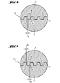
- Figs. 4 and 5 show the influence of the thermal expansion differences of the materials and changes of temperature in the sealing arrangement according to the invention.
- Fig. 4 shows a sealing surface according to the invention at mounting temperature.
- the construction and the material of the sections 2, 3 are such that a desired clearance 6 is provided on the sealing surface between such counter surfaces 2b, 3a that, depending on the application, will approach one another in operation. This situation is shown in Fig. 5.
- the sections 2 and 3 move with respect to each other due to the change in temperature, typically the raising thereof, so that the surface 2b approaches the surface 3a, whereby the clearance 6 is reduced to clearance 6a. Simultaneously, the surface 2a draws away from the surface 3b and the clearance 6b increases.
- Fig. 4 the surfaces 2b, 3a are spaced at a first distance 6 from one another in mounting conditions.
- the direction of the normal of these surfaces is approximately parallel with the primary thermal expansion direction at the surface, whereby in operating conditions the surfaces 2b, 3a are spaced at a significantly shorter distance 5.5 from one another.
Landscapes
- Engineering & Computer Science (AREA)
- Chemical & Material Sciences (AREA)
- Combustion & Propulsion (AREA)
- Mechanical Engineering (AREA)
- General Engineering & Computer Science (AREA)
- Pistons, Piston Rings, And Cylinders (AREA)
- Lubrication Of Internal Combustion Engines (AREA)
- Apparatus For Radiation Diagnosis (AREA)
Abstract
Description
- This invention relates to a piston assembly for a combustion engine in accordance with the preamble of
claim 1. - From the prior art it is known for a piston of a combustion engine to have a number of separate sections, for instance the upper section may be a separate part connected, for example, by screws to the piston body. There are several known approaches to the sealing of the joint between such sections. However, the known constructions are typically such that the piston rings, or at least the oil rings, are located above such joints, i.e. in the upper section of the piston.
- Sealing the upper section of a so-called hot combustion piston is particularly problematic since the upper section is typically made of material different from the rest of the piston. DE-A-3110292 discloses one known method of sealing the upper section of a ceramic piston by utilizing a comb structure. The problem with this kind of an approach is, among other things, how to hold the ceramic piece in place.
- In US-A-4253430 sealing by separate sealing rings is suggested instead. However this approach also is not totally without problems since the mounting of the rings at the assembly stage requires particular accuracy, and considering the thermal expansion makes the approach less feasible.
- An object of the present invention is to provide a new piston assembly for an internal combustion engine, where the problems according to the prior art are minimised. A particular object of the invention is to provide a so-called hot combustion piston assembly having piston rings located below the upper section of the piston, and where the upper section and the rest of the piston are engaged with one another tightly and firmly. In this specification a so-called hot combustion piston refers to a piston in which the surface abutting onto the combustion chamber is made of a material having a reduced heat conductivity.
- According to the present invention there is provided a piston assembly for an internal combustion engine comprising an upper section abutting onto the combustion chamber of the cylinder, and a piston skirt in connection with the upper section, and a sealing arrangement utilising heat expansion for sealing the joint between the upper section and the skirt, characterised in that the sealing arrangement between the upper section and the skirt is arranged to operate under working pressure, and in that the sealing arrangement comprises several operationally in succession provided counter surfaces, which are arranged with respect to one another so that their mutual distance is reduced at the working temperature of the surfaces.
- The sealing arrangement is at least partly based on the influence of the difference between the mounting and working temperatures of the upper section and the piston skirt, preferably on the different thermal expansion properties of the upper section and the piston skirt.
- The performance can be enhanced by selecting the materials of the upper section and the piston skirt so that their thermal expansion properties differ from one another, whereby the sealing arrangement comprises counter surfaces provided in the upper section and the piston skirt, which surfaces are arranged with respect to each other so that their mutual distance is minimised at the working temperature of the surfaces.
- The invention relates especially to a piston assembly in which grooves of the piston rings have such a location that the joining point of the upper section and the skirt has to operate under compression pressure when the piston assembly is in operation.
- The sealing arrangement between the upper section and the skirt of the piston conveniently comprises several surface sections, the surfaces of the upper section and the skirt being substantially parallel, whereby at mounting temperature the surfaces are spaced at a first distance from each other, and the direction of the normal of which surface sections is at the surface section approximately parallel with the main thermal expansion direction, whereby at working temperature the surfaces are spaced at a second distance from one another, and the second distance is shorter than the first distance. Preferably the second distance is substantially such that the surfaces are attached to one another.
- The sealing arrangement is preferably provided so that it consists of alternating grooves and protrusions in the upper section and the skirt forming the counter surfaces in such a way that the protrusion of one counter surface is always facing the groove of the other counter surface.
- According to one embodiment the counter surfaces form a screw thread in the direction of the longitudinal axis of the piston. Preferably, the counter surfaces form a trapezoidal thread in the direction of the longitudinal axis of the piston. In some cases the counter surfaces can also comprise a sealing surface deviating from the direction of the longitudinal axis of the piston.
- The sealing arrangement according to the invention suitably comprises several counter surfaces operationally in succession and arranged in relation to each other so that their mutual distance is reduced at the working temperature of the surfaces and that a pressure balancing chamber is formed between two successive, tightly arranged counter surface pairs.
- When applying the invention the skirt section of the piston is made of such material that its thermal expansion coefficient is from 10 x 10-6/K to 13 x 10-6/K and the thermal expansion coefficient of the upper section material is typically from 13 x 10-6/K to 17 x 10-6/K.
- An embodiment of the invention will now be described, by way of example only, with particular reference to the accompanying drawings, in which:
- Fig. 1 shows schematically a piston assembly, according to the present invention, for an internal combustion engine;
- Fig. 2 is an enlargement of part of Figure 1, depicted at II, showing the sealing surface between the upper section and the skirt of the piston assembly;
- Fig. 3 is an enlargement of part of Figure 1, depicted at III, showing the sealing surface between the upper section and the skirt of the piston assembly;
- Fig. 4 shows a sealing surface between upper and skirt sections of the piston assembly according to the invention at mounting temperature; and
- Fig. 5 shows a sealing surface according to Fig. 4 at working temperature.
-
- In Fig. 1 the
reference number 1 generally designates a piston assembly for an internal combustion engine comprising anupper section 2 abutting onto the combustion chamber of the combustion engine cylinder and apiston skirt 3 in connection with the upper section. Fig. 1 is greatly simplified and in practice the piston assembly comprises several kinds of additional arrangements which are not shown herewith. - The
piston assembly 1 comprisesgrooves 4 for piston rings. In thepiston assembly 1 according to the invention thegrooves 4 of the piston rings have such a location that the joining point of theupper section 2 and theskirt 3 has to operate under working pressure when the piston assembly is in operation. This is due to the fact that the material of the upper section is typically such that the piston rings cannot be provided therein. - In order to provide sufficient tightness the mating surfaces between the
upper section 2 and theskirt 3 of the piston assembly comprises sealing arrangements 1.2, 1.3, which will be described below. Here the sealing arrangement comprises both an arrangement parallel with the longitudinal axis of the piston and an arrangement deviating from the longitudinal axis. The sealing arrangements 1.2, 1.3 are provided by utilising the influence of the difference between the mounting and working temperatures of the piston assembly. An advantageous sealing effect can be achieved by selecting the upper section and skirt materials so that by any structure of the sealing arrangements 1.2, 1.3, respectively, the reaching of the working temperature makes the counter surfaces included in the sealing arrangement between theupper section 2 and theskirt 3 move with respect to one another, due to different thermal expansion, so that sufficient tightness is achieved or the tightness is considerably improved. The sealing effect can be achieved or it can be improved also by considering the fact that theupper section 2 of the piston is, in operating conditions, at a higher temperature than the rest of the piston assembly. - Fig. 2 shows in more detail the sealing arrangement 1.2 adapted to the cylindrical mating surface and which is generally parallel with the longitudinal axis of the piston. The counter surfaces comprise several grooves and
protrusions 5 so that the protrusion of one surface is always facing the groove of the other surface. Here, the sealing arrangement 1.2 between theupper section 2 and theskirt 3 of the piston comprisesseveral surface sections surfaces 2b - 3a located between thetight surface contacts 2a - 3b. Thus the sealing arrangement according to the invention comprises several operationallysuccessive surface sections 2a - 3b in each other's immediate vicinity as well as pressure balancing chambers between two such surface sections. Operational successiveness refers to the fact that as a certain pressure difference prevails over the sealing arrangement, the gases tend to flow along a particular flow path towards the low pressure. - Fig. 3 shows in more detail the sealing arrangement 1.3 provided in the piston assembly in the direction substantially normal or perpendicular to its longitudinal axis. Thus the grooves and protrusions are concentric with each other. Also in this embodiment the grooves of the counter surfaces are preferably somewhat larger than the protrusions, whereby
successive chambers 2b - 3a located between thetight surface contacts 2a - 3b are provided in the sealing arrangement, while the surface sections move with respect to one another as a result of changes and/or differences of temperature. - Figs. 4 and 5 show the influence of the thermal expansion differences of the materials and changes of temperature in the sealing arrangement according to the invention. Fig. 4 shows a sealing surface according to the invention at mounting temperature. The construction and the material of the
sections such counter surfaces sections surface 2b approaches thesurface 3a, whereby the clearance 6 is reduced toclearance 6a. Simultaneously, thesurface 2a draws away from thesurface 3b and theclearance 6b increases. - The same effect can be utilized also in a sealing arrangement in the direction of the normal of the piston assembly or even in another direction.
- In Fig. 4 the
surfaces surfaces - The invention is not limited to the above-described applications, but several other modifications are conceivable in the scope of the appended claims.
Claims (11)
- A piston assembly (1) for an internal combustion engine comprising an upper section (2) movable within the combustion chamber of the cylinder, a piston skirt (3) in connection with the upper section, and a sealing arrangement (1.2, 1.3) utilising heat expansion for sealing the joint between the upper section and the skirt, characterised in that the sealing arrangement (1.2, 1.3) between the upper section and the skirt is arranged to operate under working pressure, and in that the sealing arrangement comprises several operationally in succession provided counter surfaces which are arranged with respect to one another so that their mutual distance is reduced at the working temperature of the surfaces.
- A piston assembly according to claim 1, characterised in that the materials selected for the upper section and the piston skirt, respectively, have different thermal expansion properties, and in that the sealing arrangement comprises counter surfaces provided in the upper section (2) and the piston skirt (3), which surfaces are arranged with respect to one another so that their mutual distance is minimized at the working temperature of the surfaces.
- A piston assembly according to claim 1 or 2, characterised in that the sealing arrangement between the upper section and the skirt of the piston comprises several surface sections, where the surfaces of the upper section and the skirt are substantially parallel, whereby at mounting temperature the surfaces are located at a first distance from one another and the direction of the normal of which surface sections is approximately parallel with the main thermal expansion direction at the surface section, whereby at working temperature the surfaces are spaced at a second distance from one another, and that the second distance is shorter than the first distance.
- A piston assembly according to claim 3, characterised in that the second distance is substantially such that the surfaces are attached to one another.
- A piston assembly according to any of the preceding claims, characterised in that the sealing arrangement consists of alternating grooves and protrusions in the upper section and the skirt forming the counter surfaces in such a way that the protrusion of one counter surface is always facing the groove of the other counter surface.
- A piston assembly according to claim 5, characterised in that the counter surfaces form a thread in the direction of the longitudinal axis of the piston.
- A piston assembly according to claim 6, characterised in that the counter surfaces form a thread having a trapezoidal section in the direction of the longitudinal axis of the piston.
- A piston assembly according to claim 5, characterised in that the counter surfaces form a sealing surface deviating from the direction of the longitudinal axis of the piston.
- A piston assembly (1) according to any of the preceding claims comprising grooves (4) for piston rings, characterised in that the grooves (4) of the piston rings have such a location that the joining point of the upper section and the skirt has to operate under compression pressure when the piston assembly is in operation.
- A piston assembly (1) according to any of the preceding claims, characterised in that the sealing arrangement comprises several operationally in succession provided counter surfaces, which are arranged with respect to one another so that their mutual distance is reduced at the working temperature of the surfaces, and that a pressure balancing chamber is formed between two successive, tightly arranged counter surface pairs (2a - 3b).
- An internal combustion engine provided with a piston assembly according to any one of the previous claims.
Applications Claiming Priority (2)
| Application Number | Priority Date | Filing Date | Title |
|---|---|---|---|
| FI20011165A FI113683B (en) | 2001-06-04 | 2001-06-04 | Piston unit at an internal combustion engine |
| FI20011165 | 2001-06-04 |
Publications (3)
| Publication Number | Publication Date |
|---|---|
| EP1264979A2 true EP1264979A2 (en) | 2002-12-11 |
| EP1264979A3 EP1264979A3 (en) | 2003-07-30 |
| EP1264979B1 EP1264979B1 (en) | 2007-02-28 |
Family
ID=8561331
Family Applications (1)
| Application Number | Title | Priority Date | Filing Date |
|---|---|---|---|
| EP02253880A Expired - Lifetime EP1264979B1 (en) | 2001-06-04 | 2002-05-31 | Piston unit for combustion engine |
Country Status (4)
| Country | Link |
|---|---|
| EP (1) | EP1264979B1 (en) |
| AT (1) | ATE355450T1 (en) |
| DE (1) | DE60218382T2 (en) |
| FI (1) | FI113683B (en) |
Cited By (1)
| Publication number | Priority date | Publication date | Assignee | Title |
|---|---|---|---|---|
| DE102006015587A1 (en) * | 2006-04-04 | 2007-10-11 | Mahle International Gmbh | Top part of a built-up piston |
Citations (2)
| Publication number | Priority date | Publication date | Assignee | Title |
|---|---|---|---|---|
| US4253430A (en) | 1979-01-11 | 1981-03-03 | General Motors Corporation | Insulated oil cooled piston assembly |
| DE3110292A1 (en) | 1981-03-17 | 1982-09-30 | Rudolf Dr. 6800 Mannheim Wieser | Piston for internal combustion engine |
Family Cites Families (3)
| Publication number | Priority date | Publication date | Assignee | Title |
|---|---|---|---|---|
| US4419925A (en) * | 1978-06-15 | 1983-12-13 | Toyota Jidosha Kogyo Kabushiki Kaisha | Assembled piston for engine |
| JPS61135961A (en) * | 1984-12-05 | 1986-06-23 | Ngk Insulators Ltd | Piston with piston head made of ceramics |
| US5499572A (en) * | 1993-08-26 | 1996-03-19 | Cobble; Daniel L. | Bi-tech piston |
-
2001
- 2001-06-04 FI FI20011165A patent/FI113683B/en not_active IP Right Cessation
-
2002
- 2002-05-31 EP EP02253880A patent/EP1264979B1/en not_active Expired - Lifetime
- 2002-05-31 DE DE60218382T patent/DE60218382T2/en not_active Expired - Lifetime
- 2002-05-31 AT AT02253880T patent/ATE355450T1/en not_active IP Right Cessation
Patent Citations (2)
| Publication number | Priority date | Publication date | Assignee | Title |
|---|---|---|---|---|
| US4253430A (en) | 1979-01-11 | 1981-03-03 | General Motors Corporation | Insulated oil cooled piston assembly |
| DE3110292A1 (en) | 1981-03-17 | 1982-09-30 | Rudolf Dr. 6800 Mannheim Wieser | Piston for internal combustion engine |
Cited By (2)
| Publication number | Priority date | Publication date | Assignee | Title |
|---|---|---|---|---|
| DE102006015587A1 (en) * | 2006-04-04 | 2007-10-11 | Mahle International Gmbh | Top part of a built-up piston |
| US8079299B2 (en) | 2006-04-04 | 2011-12-20 | Mahle International Gmbh | Upper part of a composite piston |
Also Published As
| Publication number | Publication date |
|---|---|
| EP1264979A3 (en) | 2003-07-30 |
| ATE355450T1 (en) | 2006-03-15 |
| EP1264979B1 (en) | 2007-02-28 |
| FI20011165A0 (en) | 2001-06-04 |
| FI20011165L (en) | 2002-12-05 |
| FI113683B (en) | 2004-05-31 |
| DE60218382T2 (en) | 2007-11-22 |
| DE60218382D1 (en) | 2007-04-12 |
Similar Documents
| Publication | Publication Date | Title |
|---|---|---|
| CN1085297C (en) | Metallic cylinder head gasket | |
| US7328685B2 (en) | Slip joint exhaust manifolds | |
| US20050023768A1 (en) | Head gasket assembly | |
| US5341779A (en) | Beam functioning fire ring | |
| EP3030809B1 (en) | Piston ring | |
| JP2012518141A (en) | Compression piston ring | |
| US6615788B2 (en) | Piston assembly for an internal combustion engine | |
| EP1719901A1 (en) | Piston device for internal combustion engine | |
| US6196179B1 (en) | Internal combustion engine | |
| EP1264979B1 (en) | Piston unit for combustion engine | |
| KR920007667B1 (en) | Exhaust pipe for supercharged multi-cylinder internal combustion engine | |
| KR20020005706A (en) | Device with a membrane arrangement | |
| RU2156905C1 (en) | Piston ring | |
| US20240376982A1 (en) | Compression Ring Having Butt Seal, and Method | |
| US5586769A (en) | Head gasket with pre-embedded metal shim and method of using same | |
| EP1038128A1 (en) | An improved piston ring | |
| EP0019972B1 (en) | A piston for internal combustion engines having a floating flame damper ring | |
| US3550988A (en) | Piston and ptfe ring assembly for engines | |
| RU2796224C1 (en) | Piston seal for internal combustion engines | |
| CN1769659A (en) | a piston ring | |
| US11136936B2 (en) | Piston | |
| US20040237776A1 (en) | Piston ring coating | |
| SU1086262A1 (en) | Heat machine sealing device | |
| EP0412660A1 (en) | Heat-insulating piston | |
| JP2000130583A (en) | Compound double piston ring for pressure ring |
Legal Events
| Date | Code | Title | Description |
|---|---|---|---|
| PUAI | Public reference made under article 153(3) epc to a published international application that has entered the european phase |
Free format text: ORIGINAL CODE: 0009012 |
|
| AK | Designated contracting states |
Kind code of ref document: A2 Designated state(s): AT BE CH CY DE DK ES FI FR GB GR IE IT LI LU MC NL PT SE TR |
|
| AX | Request for extension of the european patent |
Free format text: AL;LT;LV;MK;RO;SI |
|
| PUAL | Search report despatched |
Free format text: ORIGINAL CODE: 0009013 |
|
| AK | Designated contracting states |
Designated state(s): AT BE CH CY DE DK ES FI FR GB GR IE IT LI LU MC NL PT SE TR |
|
| AX | Request for extension of the european patent |
Extension state: AL LT LV MK RO SI |
|
| RAP1 | Party data changed (applicant data changed or rights of an application transferred) |
Owner name: WAERTSILAE FINLAND OY |
|
| 17P | Request for examination filed |
Effective date: 20040119 |
|
| AKX | Designation fees paid |
Designated state(s): AT BE CH CY DE DK ES FI FR GB GR IE IT LI LU MC NL PT SE TR |
|
| GRAP | Despatch of communication of intention to grant a patent |
Free format text: ORIGINAL CODE: EPIDOSNIGR1 |
|
| GRAS | Grant fee paid |
Free format text: ORIGINAL CODE: EPIDOSNIGR3 |
|
| GRAA | (expected) grant |
Free format text: ORIGINAL CODE: 0009210 |
|
| AK | Designated contracting states |
Kind code of ref document: B1 Designated state(s): AT BE CH CY DE DK ES FI FR GB GR IE IT LI LU MC NL PT SE TR |
|
| PG25 | Lapsed in a contracting state [announced via postgrant information from national office to epo] |
Ref country code: NL Free format text: LAPSE BECAUSE OF FAILURE TO SUBMIT A TRANSLATION OF THE DESCRIPTION OR TO PAY THE FEE WITHIN THE PRESCRIBED TIME-LIMIT Effective date: 20070228 Ref country code: BE Free format text: LAPSE BECAUSE OF FAILURE TO SUBMIT A TRANSLATION OF THE DESCRIPTION OR TO PAY THE FEE WITHIN THE PRESCRIBED TIME-LIMIT Effective date: 20070228 Ref country code: LI Free format text: LAPSE BECAUSE OF FAILURE TO SUBMIT A TRANSLATION OF THE DESCRIPTION OR TO PAY THE FEE WITHIN THE PRESCRIBED TIME-LIMIT Effective date: 20070228 Ref country code: FI Free format text: LAPSE BECAUSE OF FAILURE TO SUBMIT A TRANSLATION OF THE DESCRIPTION OR TO PAY THE FEE WITHIN THE PRESCRIBED TIME-LIMIT Effective date: 20070228 Ref country code: CH Free format text: LAPSE BECAUSE OF FAILURE TO SUBMIT A TRANSLATION OF THE DESCRIPTION OR TO PAY THE FEE WITHIN THE PRESCRIBED TIME-LIMIT Effective date: 20070228 Ref country code: AT Free format text: LAPSE BECAUSE OF FAILURE TO SUBMIT A TRANSLATION OF THE DESCRIPTION OR TO PAY THE FEE WITHIN THE PRESCRIBED TIME-LIMIT Effective date: 20070228 Ref country code: DK Free format text: LAPSE BECAUSE OF FAILURE TO SUBMIT A TRANSLATION OF THE DESCRIPTION OR TO PAY THE FEE WITHIN THE PRESCRIBED TIME-LIMIT Effective date: 20070228 |
|
| REG | Reference to a national code |
Ref country code: GB Ref legal event code: FG4D |
|
| REG | Reference to a national code |
Ref country code: CH Ref legal event code: EP |
|
| REF | Corresponds to: |
Ref document number: 60218382 Country of ref document: DE Date of ref document: 20070412 Kind code of ref document: P |
|
| REG | Reference to a national code |
Ref country code: IE Ref legal event code: FG4D |
|
| PG25 | Lapsed in a contracting state [announced via postgrant information from national office to epo] |
Ref country code: SE Free format text: LAPSE BECAUSE OF FAILURE TO SUBMIT A TRANSLATION OF THE DESCRIPTION OR TO PAY THE FEE WITHIN THE PRESCRIBED TIME-LIMIT Effective date: 20070531 |
|
| PG25 | Lapsed in a contracting state [announced via postgrant information from national office to epo] |
Ref country code: ES Free format text: LAPSE BECAUSE OF FAILURE TO SUBMIT A TRANSLATION OF THE DESCRIPTION OR TO PAY THE FEE WITHIN THE PRESCRIBED TIME-LIMIT Effective date: 20070608 |
|
| PG25 | Lapsed in a contracting state [announced via postgrant information from national office to epo] |
Ref country code: PT Free format text: LAPSE BECAUSE OF FAILURE TO SUBMIT A TRANSLATION OF THE DESCRIPTION OR TO PAY THE FEE WITHIN THE PRESCRIBED TIME-LIMIT Effective date: 20070730 |
|
| NLV1 | Nl: lapsed or annulled due to failure to fulfill the requirements of art. 29p and 29m of the patents act | ||
| REG | Reference to a national code |
Ref country code: CH Ref legal event code: PL |
|
| EN | Fr: translation not filed | ||
| PLBE | No opposition filed within time limit |
Free format text: ORIGINAL CODE: 0009261 |
|
| STAA | Information on the status of an ep patent application or granted ep patent |
Free format text: STATUS: NO OPPOSITION FILED WITHIN TIME LIMIT |
|
| GBPC | Gb: european patent ceased through non-payment of renewal fee |
Effective date: 20070531 |
|
| PG25 | Lapsed in a contracting state [announced via postgrant information from national office to epo] |
Ref country code: MC Free format text: LAPSE BECAUSE OF NON-PAYMENT OF DUE FEES Effective date: 20070531 |
|
| 26N | No opposition filed |
Effective date: 20071129 |
|
| PG25 | Lapsed in a contracting state [announced via postgrant information from national office to epo] |
Ref country code: IT Free format text: LAPSE BECAUSE OF FAILURE TO SUBMIT A TRANSLATION OF THE DESCRIPTION OR TO PAY THE FEE WITHIN THE PRESCRIBED TIME-LIMIT Effective date: 20070228 Ref country code: GR Free format text: LAPSE BECAUSE OF FAILURE TO SUBMIT A TRANSLATION OF THE DESCRIPTION OR TO PAY THE FEE WITHIN THE PRESCRIBED TIME-LIMIT Effective date: 20070529 Ref country code: FR Free format text: LAPSE BECAUSE OF FAILURE TO SUBMIT A TRANSLATION OF THE DESCRIPTION OR TO PAY THE FEE WITHIN THE PRESCRIBED TIME-LIMIT Effective date: 20071019 |
|
| PG25 | Lapsed in a contracting state [announced via postgrant information from national office to epo] |
Ref country code: GB Free format text: LAPSE BECAUSE OF NON-PAYMENT OF DUE FEES Effective date: 20070531 Ref country code: IE Free format text: LAPSE BECAUSE OF NON-PAYMENT OF DUE FEES Effective date: 20070531 |
|
| PG25 | Lapsed in a contracting state [announced via postgrant information from national office to epo] |
Ref country code: FR Free format text: LAPSE BECAUSE OF FAILURE TO SUBMIT A TRANSLATION OF THE DESCRIPTION OR TO PAY THE FEE WITHIN THE PRESCRIBED TIME-LIMIT Effective date: 20070228 |
|
| PG25 | Lapsed in a contracting state [announced via postgrant information from national office to epo] |
Ref country code: CY Free format text: LAPSE BECAUSE OF FAILURE TO SUBMIT A TRANSLATION OF THE DESCRIPTION OR TO PAY THE FEE WITHIN THE PRESCRIBED TIME-LIMIT Effective date: 20070228 |
|
| PG25 | Lapsed in a contracting state [announced via postgrant information from national office to epo] |
Ref country code: LU Free format text: LAPSE BECAUSE OF NON-PAYMENT OF DUE FEES Effective date: 20070531 |
|
| PG25 | Lapsed in a contracting state [announced via postgrant information from national office to epo] |
Ref country code: TR Free format text: LAPSE BECAUSE OF FAILURE TO SUBMIT A TRANSLATION OF THE DESCRIPTION OR TO PAY THE FEE WITHIN THE PRESCRIBED TIME-LIMIT Effective date: 20070228 |
|
| PGFP | Annual fee paid to national office [announced via postgrant information from national office to epo] |
Ref country code: DE Payment date: 20180518 Year of fee payment: 17 |
|
| REG | Reference to a national code |
Ref country code: DE Ref legal event code: R119 Ref document number: 60218382 Country of ref document: DE |
|
| PG25 | Lapsed in a contracting state [announced via postgrant information from national office to epo] |
Ref country code: DE Free format text: LAPSE BECAUSE OF NON-PAYMENT OF DUE FEES Effective date: 20191203 |