EP1264753A2 - Overload protection device for a truck-mounted brake assembly - Google Patents
Overload protection device for a truck-mounted brake assembly Download PDFInfo
- Publication number
- EP1264753A2 EP1264753A2 EP02291208A EP02291208A EP1264753A2 EP 1264753 A2 EP1264753 A2 EP 1264753A2 EP 02291208 A EP02291208 A EP 02291208A EP 02291208 A EP02291208 A EP 02291208A EP 1264753 A2 EP1264753 A2 EP 1264753A2
- Authority
- EP
- European Patent Office
- Prior art keywords
- protection device
- overload protection
- disposed
- body member
- compression
- Prior art date
- Legal status (The legal status is an assumption and is not a legal conclusion. Google has not performed a legal analysis and makes no representation as to the accuracy of the status listed.)
- Granted
Links
Images

Classifications
-
- B—PERFORMING OPERATIONS; TRANSPORTING
- B60—VEHICLES IN GENERAL
- B60T—VEHICLE BRAKE CONTROL SYSTEMS OR PARTS THEREOF; BRAKE CONTROL SYSTEMS OR PARTS THEREOF, IN GENERAL; ARRANGEMENT OF BRAKING ELEMENTS ON VEHICLES IN GENERAL; PORTABLE DEVICES FOR PREVENTING UNWANTED MOVEMENT OF VEHICLES; VEHICLE MODIFICATIONS TO FACILITATE COOLING OF BRAKES
- B60T17/00—Component parts, details, or accessories of power brake systems not covered by groups B60T8/00, B60T13/00 or B60T15/00, or presenting other characteristic features
- B60T17/18—Safety devices; Monitoring
- B60T17/22—Devices for monitoring or checking brake systems; Signal devices
- B60T17/228—Devices for monitoring or checking brake systems; Signal devices for railway vehicles
-
- B—PERFORMING OPERATIONS; TRANSPORTING
- B61—RAILWAYS
- B61H—BRAKES OR OTHER RETARDING DEVICES SPECIALLY ADAPTED FOR RAIL VEHICLES; ARRANGEMENT OR DISPOSITION THEREOF IN RAIL VEHICLES
- B61H13/00—Actuating rail-vehicle brakes
- B61H13/34—Details
- B61H13/38—Suspension of transmitting mechanisms
Definitions
- the present invention relates, in general, to a truck-mounted brake assembly, and more particularly, to an overload protection device for a truck-mounted brake assembly on a railcar.
- the brakes on a truck-mounted brake assembly operate through the brake rigging either pneumatically, in response to the supply and release of compressed air at a brake cylinder device, or manually, in response to the operation of the railway car handbrake wheel.
- the assembly consists of truss-type brake beams, with one beam having an expansible brake actuator in the form of a brake cylinder mounted thereon.
- the brake rigging operates in response to the supply and release of compressed air from the brake cylinder. Having its fixed end secured to the left-hand side of the compression member of the brake beam, the brake cylinder responds to the supply of compressed air by an axial expansion of its free end relative to its fixed end.
- the free end of the brake cylinder effects rotation of the equalizing lever about a pivot pin in a counterclockwise direction, as the brake cylinder expands axially with the supply of compressed air.
- This counterclockwise rotation of the equalizing lever results in the force-transmitting member being moved in the direction of the right hand, to effect counterclockwise rotation of the equalizing lever about its pivot pin.
- a portion of the force-transmitting member is secured to the fixed end of the brake cylinder, where resistance to movement is encountered at the end of the equalizing lever connected to the force-transmitting member by the pin, so that this lever acts as a second-class lever.
- the force exerted at the other end of the equalizing lever from the force-transmitting member causes the equalizing lever to pivot about its connection with the force-transmitting member and thereby move the brake beam in the direction of the right hand through the connection of the equalizing lever with the strut bar, thereby bringing the brake shoes of the brake head and brake shoe assemblies associated with the brake beam into engagement with the wheel treads of the wheel/axle unit.
- the connection of equalizing lever with the force-transmitting member becomes solid, and the equalizing lever becomes a second-class lever.
- the continued expansion of the free end of the brake cylinder causes a counterclockwise rotation of the equalizing lever to take place by pivotal rotation about the pin connection of the equalizing lever with the force-transmitting member. Accordingly, the force of expansion of the brake cylinder acts through the pin of the equalizing lever and the strut bar to force the brake beam in the direction of the left-hand, thereby bringing the brake shoes of the brake head and the brake shoe assemblies associated with the other brake beam into engagement with the wheel treads of the second wheel/axle unit.
- a common practice in the railway industry is to activate the pneumatic, and then the manual brake systems on a single railcar as a precaution against unwanted or unexpected movement of the car. This multiplies the forces on the brake assembly; therefore the brake beams may be subjected to a force exceeding their ultimate load capacity, thus causing deflection and premature failure.
- the present invention is designed with a preloaded compression member to absorb the excess force before deflection and possible failure of the brake beam occurs.
- the present invention provides an overload protection device for a truck-mounted brake assembly comprising a body member having a first end, a second end, at least one cavity of a predetermined size and shape disposed within the body member, and a compression member of a predetermined size, shape, material, and load rating, having a primary end and a secondary end.
- the compression member is compressed to a predetermined initial load, and is disposed within the cavity of the body member.
- the present invention further comprises a first means secured to and disposed on the first end of the body member for engagement with a portion of a brake assembly, and a second means disposed on the second end of the body member for attaching to a force-transmitting member.
- a first portion of the second means is engageable with the compression member for transmitting an excess force generated from a railcar brake assembly to the compression member, whereby the overload protection device will compensate for a potential railcar brake overload condition.
- the present invention provides an overload protection device for a truck-mounted brake assembly comprising a body member having a first end, a second end, at least one cavity of a predetermined size and shape disposed within the body member, and a compression member of a predetermined size, shape, material, and load rating.
- the compression member is compressed to a predetermined initial load, and is disposed within the cavity of the body member.
- a flange of a predetermined size and shape has a first surface and a second surface. The first surface is disposed on the second end of the body member.
- a first means is secured to and disposed on the first end of the body member for engagement with a portion of the brake assembly.
- a second means is reciprocally mounted adjacent to the second end of the body member for attaching to a force-transmitting member.
- a first portion of the second means is engageable with the compression member for transmitting an excess force generated from a railcar brake assembly to the compression member.
- a retaining element is secured to and disposed on the second surface of the flange.
- the retaining element has an aperture of a predetermined size and shape concentrically disposed therein, wherein a second portion of the second means is reciprocally disposed therein.
- the overload protection device will compensate for a potential railcar brake overload condition.
- the present invention provides an overload protection device for a truck-mounted brake assembly comprising a body member having a first end, a second end, and at least one cavity of a predetermined size and shape disposed within the body member.
- a compression member of a predetermined size, shape, material, and load rating has a primary end, a secondary end, and a concentric bore of a predetermined size and shape disposed from the primary end to the secondary end.
- the compression member is disposed within the cavity of the body member.
- a first means is secured to and disposed on the first end of the body member for engaging a portion of the brake assembly.
- a second means is disposed within the concentric bore of the compression member, and is engageable with the compression member and connectable to a force-transmitting member.
- a securement member is disposed on the second end of the body member for securing the compression member in the cavity of the body member, whereby the overload protection device will compensate for a potential railcar brake overload condition.
- Another object of the present invention is to provide a device to protect brake overload in a truck-mounted brake assembly on a railcar by compensating for multiple forces that may exceed the ultimate load capacity of the brake beams.
- Still a further object of the present invention is to provide a device to protect brake overload in a truck-mounted brake assembly on a railcar by absorbing the excess force before deflection and possible brake beam failure occurs.
- an overload protection device for a truck-mounted railcar brake assembly, generally designated 56.
- the overload protection device 10 comprises a body member 12 having a first end 14, a second end 16, and at least one cavity of a predetermined size and shape disposed within the body member 12.
- a compression member 20 of a predetermined size, shape, material, and load rating is compressed to a predetermined initial load and disposed within the cavity 18 of the body member 12.
- the compression member 20 is selected from the group consisting of compression spring, Belleville spring, and elastomer. It is also preferred that the predetermined initial load of the compression member 20 is about 10,000 pounds.
- a first means 22 is secured to and disposed on the first end 14 of the body member for engagement with a portion of the brake assembly 56.
- a second means, generally designated 24, is disposed on the second end 16 of the body member 12 for attaching to a force-transmitting member 58.
- a first portion 32 of the second means 24 is engageable with the compression member 20 for transmitting an excess force generated from the railcar brake assembly 56 to the compression member 20.
- the overload protection device 10 will compensate for a potential railcar brake overload condition.
- the overload protection device 10 for a truck-mounted railcar brake assembly generally designated 56.
- the overload protection device 10 comprises a body member 12 having a first end 14, a second end 16, and at least one cavity 18 of a predetermined size and shape disposed within the body member 12.
- a compression member 20 of a predetermined size, shape, material, and load rating is compressed to a predetermined initial load and disposed within the cavity 18 of the body member 12.
- the compression member 20 is selected from the group consisting of compression spring, Belleville spring, and elastomer. It is also preferred that the predetermined initial load of the compression member 20 is about 10,000 pounds.
- a flange 26 of a predetermined size and shape has a first surface 28 and a second surface 30.
- the preferred shape of the flange 26 is annular.
- the first surface 28 is disposed on the second end 16 of the body member 12.
- a first means 22 is secured to and disposed on the first end 14 of the body member 12 for engagement with a portion of the brake assembly 56.
- a second means, generally designated 24, is reciprocally mounted adjacent to the second end 16 of the body member 12 for attaching to a force-transmitting member 58.
- a first portion 32 of the second means 24 is engageable with the compression member 20 for transmitting an excess force generated from the railcar brake assembly 56 to the compression member 20.
- the first portion 32 is a plate-like member.
- a retaining element 34 is secured to and disposed on the second surface 30 of the flange 26.
- the retaining element 34 has an aperture 36 of a predetermined size and shape concentrically disposed therein; wherein a second portion 38 of the second means 24 is reciprocally disposed therein.
- the second portion 38 is a push rod
- the retaining element 34 has an attachment means 40 to said flange 26, which is a plurality of bolts having a predetermined length and diameter. This arrangement will permit the overload protection device 10 to compensate for a potential railcar brake overload condition.
- an overload protection device for a truck-mounted railcar brake assembly generally designated 56.
- the overload protection device 10 comprises a body member 12 having a first end 14, a second end 16, and at least one cavity 18 of a predetermined size and shape disposed within the body member 12.
- the cavity 18 is cylindrical shaped.
- a compression member 20 of a predetermined size, shape, material, and load rating has a concentric bore 42 of a predetermined size and shape disposed within.
- the preferred shape of the compression member 20 is cylindrical.
- the compression member 20 is compressed to a predetermined initial load, and disposed within the cavity 18 of the body member 12.
- an alignment means 44 which is at least one guide pin of a predetermined length and diameter, is disposed within the cavity 18 of the body member 12 for engaging with the compression member 20.
- This alignment means 44 will maintain the compression member 20 in a predetermined location.
- the compression member 20 is selected from the group consisting of compression spring, Belleville spring, and elastomer. It is also preferred that the predetermined initial load of the compression member 20 is about 10,000 pounds.
- a first means 22 is secured to and disposed on the first end 14 of the body member 12 for engaging a portion of the brake assembly 56. It is preferred that the first means 22 is an integrally cast coupling device.
- a second means 24 is disposed within the concentric bore 42 of the compression member 20.
- This second means 24 is engageable with the compression member 20 and connectable to a force- transmitting member 58.
- the second means 24 is a cylindrical tube having a primary end 46 and a secondary end 48, disposed within the concentric bore 42 of the compression member 20.
- the second means 24 has a threaded inside diameter 54 to accept a threaded push rod.
- the primary end 46 has a retaining member 50 disposed thereon and engageable with the compression member 20.
- the retaining member 50 is a washer of a predetermined thickness, inside diameter, and outside diameter.
- the washer is welded to the second means 24.
- the secondary end 48 has a compression element 52 disposed thereon. The compression element 52 is engageable with the compression member 20.
- the compression element 52 is a washer of a predetermined thickness, inside diameter, and outside diameter.
- the washer is welded to the second means 24.
- a retaining element 34 is secured to and disposed on the second end 16 of the body member 12 for securing the compression member 20 in the cavity 18 of the body member 12.
- the retaining element 34 is a washer of a predetermined thickness, inside diameter, and outside diameter, and is welded to the second end 16 of the body member 12.
- the overload protection device 10 will compensate for a potential railcar brake overload condition.
Landscapes
- Engineering & Computer Science (AREA)
- Mechanical Engineering (AREA)
- Transportation (AREA)
- Braking Arrangements (AREA)
Abstract
Description
- The present invention relates, in general, to a truck-mounted brake assembly, and more particularly, to an overload protection device for a truck-mounted brake assembly on a railcar.
- Prior to the present invention, the brakes on a truck-mounted brake assembly operate through the brake rigging either pneumatically, in response to the supply and release of compressed air at a brake cylinder device, or manually, in response to the operation of the railway car handbrake wheel. As illustrated in Figure 3, the assembly consists of truss-type brake beams, with one beam having an expansible brake actuator in the form of a brake cylinder mounted thereon. The brake rigging operates in response to the supply and release of compressed air from the brake cylinder. Having its fixed end secured to the left-hand side of the compression member of the brake beam, the brake cylinder responds to the supply of compressed air by an axial expansion of its free end relative to its fixed end. Being connected to an equalizing lever by a force transmitting member, the free end of the brake cylinder effects rotation of the equalizing lever about a pivot pin in a counterclockwise direction, as the brake cylinder expands axially with the supply of compressed air. This counterclockwise rotation of the equalizing lever results in the force-transmitting member being moved in the direction of the right hand, to effect counterclockwise rotation of the equalizing lever about its pivot pin. A portion of the force-transmitting member is secured to the fixed end of the brake cylinder, where resistance to movement is encountered at the end of the equalizing lever connected to the force-transmitting member by the pin, so that this lever acts as a second-class lever. The force exerted at the other end of the equalizing lever from the force-transmitting member causes the equalizing lever to pivot about its connection with the force-transmitting member and thereby move the brake beam in the direction of the right hand through the connection of the equalizing lever with the strut bar, thereby bringing the brake shoes of the brake head and brake shoe assemblies associated with the brake beam into engagement with the wheel treads of the wheel/axle unit. Once this brake shoe engagement occurs, the connection of equalizing lever with the force-transmitting member becomes solid, and the equalizing lever becomes a second-class lever. Thus, the continued expansion of the free end of the brake cylinder causes a counterclockwise rotation of the equalizing lever to take place by pivotal rotation about the pin connection of the equalizing lever with the force-transmitting member. Accordingly, the force of expansion of the brake cylinder acts through the pin of the equalizing lever and the strut bar to force the brake beam in the direction of the left-hand, thereby bringing the brake shoes of the brake head and the brake shoe assemblies associated with the other brake beam into engagement with the wheel treads of the second wheel/axle unit.
- An example of this type of truck-mounted brake assembly is taught in U.S. Patent No. 4,613,016. The teachings of this reference are incorporated herein by reference thereto.
- Similarly, rotation of the end of the actuating lever in a counterclockwise rotation, when the handbrake chain is taken up in a well-known manner, affects the same result. An example of this type of truck-mounted brake assembly is taught in U.S. Patent No. 5,069,312. The teachings of this reference are incorporated herein by reference thereto.
- A common practice in the railway industry is to activate the pneumatic, and then the manual brake systems on a single railcar as a precaution against unwanted or unexpected movement of the car. This multiplies the forces on the brake assembly; therefore the brake beams may be subjected to a force exceeding their ultimate load capacity, thus causing deflection and premature failure. The present invention is designed with a preloaded compression member to absorb the excess force before deflection and possible failure of the brake beam occurs.
- In a first aspect, the present invention provides an overload protection device for a truck-mounted brake assembly comprising a body member having a first end, a second end, at least one cavity of a predetermined size and shape disposed within the body member, and a compression member of a predetermined size, shape, material, and load rating, having a primary end and a secondary end. The compression member is compressed to a predetermined initial load, and is disposed within the cavity of the body member. The present invention further comprises a first means secured to and disposed on the first end of the body member for engagement with a portion of a brake assembly, and a second means disposed on the second end of the body member for attaching to a force-transmitting member. A first portion of the second means is engageable with the compression member for transmitting an excess force generated from a railcar brake assembly to the compression member, whereby the overload protection device will compensate for a potential railcar brake overload condition.
- In a further aspect, the present invention provides an overload protection device for a truck-mounted brake assembly comprising a body member having a first end, a second end, at least one cavity of a predetermined size and shape disposed within the body member, and a compression member of a predetermined size, shape, material, and load rating. The compression member is compressed to a predetermined initial load, and is disposed within the cavity of the body member. A flange of a predetermined size and shape has a first surface and a second surface. The first surface is disposed on the second end of the body member. A first means is secured to and disposed on the first end of the body member for engagement with a portion of the brake assembly. A second means is reciprocally mounted adjacent to the second end of the body member for attaching to a force-transmitting member. A first portion of the second means is engageable with the compression member for transmitting an excess force generated from a railcar brake assembly to the compression member. A retaining element is secured to and disposed on the second surface of the flange. The retaining element has an aperture of a predetermined size and shape concentrically disposed therein, wherein a second portion of the second means is reciprocally disposed therein. The overload protection device will compensate for a potential railcar brake overload condition.
- In still a further aspect, the present invention provides an overload protection device for a truck-mounted brake assembly comprising a body member having a first end, a second end, and at least one cavity of a predetermined size and shape disposed within the body member. A compression member of a predetermined size, shape, material, and load rating has a primary end, a secondary end, and a concentric bore of a predetermined size and shape disposed from the primary end to the secondary end. The compression member is disposed within the cavity of the body member. A first means is secured to and disposed on the first end of the body member for engaging a portion of the brake assembly. A second means is disposed within the concentric bore of the compression member, and is engageable with the compression member and connectable to a force-transmitting member. A securement member is disposed on the second end of the body member for securing the compression member in the cavity of the body member, whereby the overload protection device will compensate for a potential railcar brake overload condition.
- In addition to the various objects of the invention that have been described above, various other objects and advantages of the invention will become more readily apparent to those persons skilled in the relevant art from the following more detailed description of the invention, particularly, when such description is taken in conjunction with the attached drawing figures and the appended claims.
- It is therefore a primary object of the present invention to provide a device to protect brake overload in a truck-mounted brake assembly on a railcar.
- Another object of the present invention is to provide a device to protect brake overload in a truck-mounted brake assembly on a railcar by compensating for multiple forces that may exceed the ultimate load capacity of the brake beams.
- Still a further object of the present invention is to provide a device to protect brake overload in a truck-mounted brake assembly on a railcar by absorbing the excess force before deflection and possible brake beam failure occurs.
- In addition to the various objects of the invention that have been described above, various other objects and advantages of the invention will become more readily apparent to those persons skilled in the relevant art from the following more detailed description of the invention, particularly, when such description is taken in conjunction with the attached drawing figures and the appended claims.
-
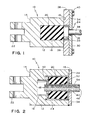
- Figure 1 is an elevation cross-sectional view of the overload protection device;
- Figure 2 is an elevation cross-sectional view of an alternate configuration of the overload protection device; and
- Figure 3 is a plan view, which shows a truck-mounted brake assembly having a conventional prior art pneumatic brake cylinder device, and is accordingly labeled "Prior Art".
-
- Prior to proceeding to a more detailed description of the invention, it should be noted that identical components having identical functions have been designated with identical reference numerals for the sake of clarity.
- Referring more particularly to Figures 1 and 3 of the drawings is an overload protection device, generally designated 10, for a truck-mounted railcar brake assembly, generally designated 56. The
overload protection device 10 comprises abody member 12 having afirst end 14, asecond end 16, and at least one cavity of a predetermined size and shape disposed within thebody member 12. Acompression member 20 of a predetermined size, shape, material, and load rating is compressed to a predetermined initial load and disposed within thecavity 18 of thebody member 12. Preferably, thecompression member 20 is selected from the group consisting of compression spring, Belleville spring, and elastomer. It is also preferred that the predetermined initial load of thecompression member 20 is about 10,000 pounds. Afirst means 22 is secured to and disposed on thefirst end 14 of the body member for engagement with a portion of thebrake assembly 56. A second means, generally designated 24, is disposed on thesecond end 16 of thebody member 12 for attaching to a force-transmittingmember 58. Afirst portion 32 of thesecond means 24 is engageable with thecompression member 20 for transmitting an excess force generated from therailcar brake assembly 56 to thecompression member 20. Theoverload protection device 10 will compensate for a potential railcar brake overload condition. - Now refer again to Figures 1 and 3 of the drawings. Illustrated therein is a preferred embodiment of the overload protection device, generally designated 10, for a truck-mounted railcar brake assembly generally designated 56. The
overload protection device 10 comprises abody member 12 having afirst end 14, asecond end 16, and at least onecavity 18 of a predetermined size and shape disposed within thebody member 12. Acompression member 20 of a predetermined size, shape, material, and load rating is compressed to a predetermined initial load and disposed within thecavity 18 of thebody member 12. Preferably, thecompression member 20 is selected from the group consisting of compression spring, Belleville spring, and elastomer. It is also preferred that the predetermined initial load of thecompression member 20 is about 10,000 pounds. Aflange 26 of a predetermined size and shape has afirst surface 28 and asecond surface 30. The preferred shape of theflange 26 is annular. Thefirst surface 28 is disposed on thesecond end 16 of thebody member 12. A first means 22 is secured to and disposed on thefirst end 14 of thebody member 12 for engagement with a portion of thebrake assembly 56. A second means, generally designated 24, is reciprocally mounted adjacent to thesecond end 16 of thebody member 12 for attaching to a force-transmittingmember 58. Afirst portion 32 of the second means 24 is engageable with thecompression member 20 for transmitting an excess force generated from therailcar brake assembly 56 to thecompression member 20. Preferably, thefirst portion 32 is a plate-like member. A retainingelement 34 is secured to and disposed on thesecond surface 30 of theflange 26. The retainingelement 34 has anaperture 36 of a predetermined size and shape concentrically disposed therein; wherein asecond portion 38 of the second means 24 is reciprocally disposed therein. Preferably, thesecond portion 38 is a push rod, and the retainingelement 34 has an attachment means 40 to saidflange 26, which is a plurality of bolts having a predetermined length and diameter. This arrangement will permit theoverload protection device 10 to compensate for a potential railcar brake overload condition. - Now refer more particularly to Figures 2 and 3 of the drawings. Illustrated therein is an overload protection device, generally designated 10, for a truck-mounted railcar brake assembly generally designated 56. The
overload protection device 10 comprises abody member 12 having afirst end 14, asecond end 16, and at least onecavity 18 of a predetermined size and shape disposed within thebody member 12. Preferably, thecavity 18 is cylindrical shaped. Acompression member 20 of a predetermined size, shape, material, and load rating has aconcentric bore 42 of a predetermined size and shape disposed within. The preferred shape of thecompression member 20 is cylindrical. Thecompression member 20 is compressed to a predetermined initial load, and disposed within thecavity 18 of thebody member 12. Preferably, an alignment means 44, which is at least one guide pin of a predetermined length and diameter, is disposed within thecavity 18 of thebody member 12 for engaging with thecompression member 20. This alignment means 44 will maintain thecompression member 20 in a predetermined location. It is preferred that thecompression member 20 is selected from the group consisting of compression spring, Belleville spring, and elastomer. It is also preferred that the predetermined initial load of thecompression member 20 is about 10,000 pounds. A first means 22 is secured to and disposed on thefirst end 14 of thebody member 12 for engaging a portion of thebrake assembly 56. It is preferred that the first means 22 is an integrally cast coupling device. A second means 24 is disposed within theconcentric bore 42 of thecompression member 20. This second means 24 is engageable with thecompression member 20 and connectable to a force- transmittingmember 58. Preferably, the second means 24 is a cylindrical tube having aprimary end 46 and asecondary end 48, disposed within theconcentric bore 42 of thecompression member 20. Also preferred is the second means 24 has a threaded insidediameter 54 to accept a threaded push rod. Theprimary end 46 has a retainingmember 50 disposed thereon and engageable with thecompression member 20. Preferably, the retainingmember 50 is a washer of a predetermined thickness, inside diameter, and outside diameter. Preferably, the washer is welded to thesecond means 24. Thesecondary end 48 has acompression element 52 disposed thereon. Thecompression element 52 is engageable with thecompression member 20. Preferably, thecompression element 52 is a washer of a predetermined thickness, inside diameter, and outside diameter. Preferably, the washer is welded to thesecond means 24. A retainingelement 34 is secured to and disposed on thesecond end 16 of thebody member 12 for securing thecompression member 20 in thecavity 18 of thebody member 12. Preferably, the retainingelement 34 is a washer of a predetermined thickness, inside diameter, and outside diameter, and is welded to thesecond end 16 of thebody member 12. Theoverload protection device 10 will compensate for a potential railcar brake overload condition. - Although the invention has been shown in connection with a certain specific embodiment, it will be readily apparent to those skilled in the art that various changes in form and arrangement of parts and method may be made to suit requirements without departing from the spirit and scope of the invention.
Claims (20)
- An overload protection device for a truck-mounted railcar brake assembly, said overload protection device comprising:(a) a body member having a first end, a second end, and at least one cavity of a predetermined size and shape disposed within said body member;(b) a compression member of a predetermined size, shape, material, and load rating, said compression member compressed to a predetermined initial load, and disposed within said cavity of said body member;(c) a first means secured to and disposed on said first end of said body member for engagement with a portion of such brake assembly; and(d) a second means disposed on said second end of said body member for attaching to a force transmitting member, a first portion of said second means engageable with said compression member for transmitting an excess force generated from such railcar brake assembly to said compression member, whereby said overload protection device will compensate for a potential railcar brake overload condition.
- The overload protection device according to claim 1 wherein said compression member is selected from the group consisting of a compression spring, Belleville spring, and elastomer.
- The overload protection device according to claim 1 wherein said predetermined initial load is about 10,000 pounds.
- An overload protection device for a truck-mounted railcar brake assembly, said overload protection device comprising:(a) a body member having a first end, a second end, and at least one cavity of a predetermined size and shape disposed within said body member;(b) a compression member of a predetermined size, shape, material, and load rating, said compression member compressed to a predetermined initial load, and disposed within said cavity of said body member;(c) a flange of a predetermined size and shape having a first surface and a second surface, said first surface disposed on said second end of said body member;(d) a first means secured to and disposed on said first end of said body member for engagement with a portion of such brake assembly;(e) a second means reciprocally mounted adjacent said second end of said body member for attaching to a force transmitting member, a first portion of said second means engageable with said compression member for transmitting an excess force generated from such railcar brake assembly to said compression member; and(f) a retaining element secured to and disposed on said second surface of said flange, said retaining element further having an aperture of a predetermined size and shape concentrically disposed therein, wherein a second portion of said second means is reciprocally disposed therein, whereby said overload protection device will compensate for a potential railcar brake overload condition.
- The overload protection device according to claim 4 wherein said retaining element has an attachment means to said flange.
- The overload protection device according to claim 5 wherein said attachment means is a plurality of bolts having a predetermined length and diameter.
- An overload protection device for a truck-mounted railcar brake assembly, said overload protection device comprising:(a) a body member having a first end, a second end, and at least one cavity of a predetermined size and shape disposed within said body member;(b) a compression member of a predetermined size, shape, material, and load rating, having a concentric bore of a predetermined size and shape disposed within, compressed to a predetermined initial load, said compression member disposed within said cavity of said body member;(c) a first means secured to and disposed on said first end of said body member for engaging a portion of such brake assembly;(d) a second means disposed within said concentric bore of said compression member, engageable with said compression member and connectable to a force transmitting member; and(e) a retaining element secured to and disposed on said second end of said body member for securing said compression member in said cavity of said body member, whereby said overload protection device will compensate for a potential railcar brake overload condition.
- The overload protection device according to claim 7 wherein an alignment means is disposed within said cavity of said body member for engaging said compression member for maintaining said compression member in a predetermined location.
- The overload protection device according to claim 8 wherein said alignment means is at least one guide pin of a predetermined length and diameter.
- The overload protection device according to claim 7 wherein said cavity is a cylindrical shape.
- The overload protection device according to claim 7 wherein said shape of said compression member is cylindrical.
- The overload protection device according to claim 7 wherein said first means is a coupling device.
- The overload protection device according to claim 12 wherein said coupling device is integrally cast.
- The overload protection device according to claim 7 wherein said second means is a cylindrical tube having a primary end and a secondary end, said cylindrical tube disposed within said concentric bore of said compression member, said primary end further having a retaining member disposed thereon and engageable with said compression member, and said secondary end further having a compression element disposed thereon, said compression element engageable with said compression member.
- The overload protection device according to claim 7 wherein said second means has a threaded inside diameter to accept a threaded push rod.
- The overload protection device according to claim 14 wherein said retaining member is a washer of a predetermined thickness, inside diameter, and outside diameter.
- The overload protection device according to claim 16 wherein said washer is welded to said second means.
- The overload protection device according to claim 14 wherein said compression element is a washer of a predetermined thickness, inside diameter, and outside diameter.
- The overload protection device according to claim 18 wherein said washer is welded to said second means.
- The overload protection device according to claim 7 wherein said retaining element is a washer of a predetermined thickness, inside diameter, and outside diameter, and is welded to said second end of said body member.
Applications Claiming Priority (2)
| Application Number | Priority Date | Filing Date | Title |
|---|---|---|---|
| US876612 | 2001-06-07 | ||
| US09/876,612 US6619443B2 (en) | 2001-06-07 | 2001-06-07 | Overload protection device for a truck-mounted brake assembly |
Publications (3)
| Publication Number | Publication Date |
|---|---|
| EP1264753A2 true EP1264753A2 (en) | 2002-12-11 |
| EP1264753A3 EP1264753A3 (en) | 2003-08-27 |
| EP1264753B1 EP1264753B1 (en) | 2011-03-02 |
Family
ID=25368150
Family Applications (1)
| Application Number | Title | Priority Date | Filing Date |
|---|---|---|---|
| EP02291208A Expired - Lifetime EP1264753B1 (en) | 2001-06-07 | 2002-05-16 | Overload protection device for a truck-mounted brake assembly |
Country Status (10)
| Country | Link |
|---|---|
| US (1) | US6619443B2 (en) |
| EP (1) | EP1264753B1 (en) |
| CN (1) | CN1390729A (en) |
| AU (1) | AU782221B2 (en) |
| BR (1) | BR0201427B1 (en) |
| CA (1) | CA2381857C (en) |
| DE (1) | DE60239308D1 (en) |
| MX (1) | MXPA02005696A (en) |
| NZ (1) | NZ518506A (en) |
| ZA (1) | ZA200203451B (en) |
Families Citing this family (5)
| Publication number | Priority date | Publication date | Assignee | Title |
|---|---|---|---|---|
| US8033533B2 (en) * | 2003-08-21 | 2011-10-11 | Wabtec Holding Corp. | Universal brake assembly |
| US7011194B1 (en) | 2004-08-19 | 2006-03-14 | Robert Bosch Gmbh | Drum-in-hat torque limiter |
| US20060202550A1 (en) * | 2005-03-11 | 2006-09-14 | Westinghouse Air Brake Technologies Corporation | Load protection device for a truck-mounted brake assembly |
| US8978841B2 (en) * | 2005-07-06 | 2015-03-17 | Wabtec Holding Corp | Universal brake assembly |
| CN101716963B (en) * | 2009-11-16 | 2012-11-28 | 济南吉利汽车有限公司 | Device and method for loading rod pieces in independent suspension system of vehicle |
Citations (2)
| Publication number | Priority date | Publication date | Assignee | Title |
|---|---|---|---|---|
| US4613016A (en) | 1985-08-09 | 1986-09-23 | American Standard Inc. | Single-cylinder truck-mounted brake assembly |
| US5069312A (en) | 1990-10-15 | 1991-12-03 | Westinghouse Air Brake Company | Handbrake for single-cylinder truck-mounted railway car brake |
Family Cites Families (4)
| Publication number | Priority date | Publication date | Assignee | Title |
|---|---|---|---|---|
| DE616328C (en) * | 1934-02-27 | 1935-07-25 | Bromsregulator Svenska Ab | Adjustment device for vehicle brakes |
| DE3738294A1 (en) * | 1986-11-13 | 1988-06-09 | Linke Hofmann Busch | Safety device for an automatic linkage actuator in the event of incorrect functioning of the same in the brake linkage of rail vehicles |
| US5664478A (en) * | 1996-10-08 | 1997-09-09 | Nai Anchorlok, Inc. | Spring brake actuator with corrosion fuses |
| US6279689B1 (en) * | 1999-01-20 | 2001-08-28 | Westinghouse Air Brake Company | Hydraulic parking brake for a railroad vehicle braking system |
-
2001
- 2001-06-07 US US09/876,612 patent/US6619443B2/en not_active Expired - Fee Related
-
2002
- 2002-04-15 CA CA002381857A patent/CA2381857C/en not_active Expired - Fee Related
- 2002-04-16 AU AU34351/02A patent/AU782221B2/en not_active Ceased
- 2002-04-19 NZ NZ518506A patent/NZ518506A/en unknown
- 2002-04-25 BR BRPI0201427-0A patent/BR0201427B1/en not_active IP Right Cessation
- 2002-04-30 ZA ZA200203451A patent/ZA200203451B/en unknown
- 2002-05-16 EP EP02291208A patent/EP1264753B1/en not_active Expired - Lifetime
- 2002-05-16 DE DE60239308T patent/DE60239308D1/en not_active Expired - Lifetime
- 2002-06-05 CN CN02122093A patent/CN1390729A/en active Pending
- 2002-06-07 MX MXPA02005696A patent/MXPA02005696A/en active IP Right Grant
Patent Citations (2)
| Publication number | Priority date | Publication date | Assignee | Title |
|---|---|---|---|---|
| US4613016A (en) | 1985-08-09 | 1986-09-23 | American Standard Inc. | Single-cylinder truck-mounted brake assembly |
| US5069312A (en) | 1990-10-15 | 1991-12-03 | Westinghouse Air Brake Company | Handbrake for single-cylinder truck-mounted railway car brake |
Also Published As
| Publication number | Publication date |
|---|---|
| ZA200203451B (en) | 2002-12-09 |
| EP1264753B1 (en) | 2011-03-02 |
| NZ518506A (en) | 2002-12-20 |
| DE60239308D1 (en) | 2011-04-14 |
| BR0201427B1 (en) | 2010-06-01 |
| US6619443B2 (en) | 2003-09-16 |
| CA2381857A1 (en) | 2002-12-07 |
| MXPA02005696A (en) | 2002-12-13 |
| CN1390729A (en) | 2003-01-15 |
| CA2381857C (en) | 2005-07-26 |
| AU3435102A (en) | 2002-12-12 |
| US20020185339A1 (en) | 2002-12-12 |
| BR0201427A (en) | 2003-02-11 |
| EP1264753A3 (en) | 2003-08-27 |
| AU782221B2 (en) | 2005-07-14 |
Similar Documents
| Publication | Publication Date | Title |
|---|---|---|
| US5069312A (en) | Handbrake for single-cylinder truck-mounted railway car brake | |
| EP1127766B1 (en) | Spring applied parking brake assembly | |
| US7802662B2 (en) | Slack adjuster for railway vehicle brake rigging | |
| AU2014329506B2 (en) | Manual brake release mechanism for rail vehicles | |
| US20080035432A1 (en) | Railway car hand brake lever | |
| EP0642965A1 (en) | Single actuator truck mount brake system | |
| US4552056A (en) | Manual release and automatic reset arrangement for spring-applied/air-released brake | |
| US6702073B2 (en) | Hand brake lever interface for single-cylinder truck-mounted railway car brake | |
| US6619443B2 (en) | Overload protection device for a truck-mounted brake assembly | |
| US7341128B2 (en) | Disk brake arranged TMX | |
| EP0217589A2 (en) | Rail car brake apparatus | |
| AU2006223463B2 (en) | Load protection device for a truck-mounted brake assembly | |
| US6269916B1 (en) | Brake cylinder using dual piston assemblies | |
| US3842951A (en) | Two way automatic brake adjuster | |
| US11536337B2 (en) | Slack adjuster for a brake system | |
| EP1535817B1 (en) | Improved hand brake lever interface for single-cylinder truck-mounted railway car brake | |
| EP0812751B1 (en) | A slack adjustable force transmitting cylinder | |
| CA2167013C (en) | Single actuator truck mount brake system |
Legal Events
| Date | Code | Title | Description |
|---|---|---|---|
| PUAI | Public reference made under article 153(3) epc to a published international application that has entered the european phase |
Free format text: ORIGINAL CODE: 0009012 |
|
| AK | Designated contracting states |
Kind code of ref document: A2 Designated state(s): AT BE CH CY DE DK ES FI FR GB GR IE IT LI LU MC NL PT SE TR |
|
| AX | Request for extension of the european patent |
Free format text: AL;LT;LV;MK;RO;SI |
|
| PUAL | Search report despatched |
Free format text: ORIGINAL CODE: 0009013 |
|
| AK | Designated contracting states |
Designated state(s): AT BE CH CY DE DK ES FI FR GB GR IE IT LI LU MC NL PT SE TR |
|
| AX | Request for extension of the european patent |
Extension state: AL LT LV MK RO SI |
|
| 17P | Request for examination filed |
Effective date: 20031230 |
|
| 17Q | First examination report despatched |
Effective date: 20040220 |
|
| AKX | Designation fees paid |
Designated state(s): DE FR GB IT |
|
| GRAP | Despatch of communication of intention to grant a patent |
Free format text: ORIGINAL CODE: EPIDOSNIGR1 |
|
| GRAS | Grant fee paid |
Free format text: ORIGINAL CODE: EPIDOSNIGR3 |
|
| GRAA | (expected) grant |
Free format text: ORIGINAL CODE: 0009210 |
|
| AK | Designated contracting states |
Kind code of ref document: B1 Designated state(s): DE FR GB IT |
|
| REG | Reference to a national code |
Ref country code: GB Ref legal event code: FG4D |
|
| REF | Corresponds to: |
Ref document number: 60239308 Country of ref document: DE Date of ref document: 20110414 Kind code of ref document: P |
|
| REG | Reference to a national code |
Ref country code: DE Ref legal event code: R096 Ref document number: 60239308 Country of ref document: DE Effective date: 20110414 |
|
| PLBE | No opposition filed within time limit |
Free format text: ORIGINAL CODE: 0009261 |
|
| STAA | Information on the status of an ep patent application or granted ep patent |
Free format text: STATUS: NO OPPOSITION FILED WITHIN TIME LIMIT |
|
| 26N | No opposition filed |
Effective date: 20111205 |
|
| REG | Reference to a national code |
Ref country code: DE Ref legal event code: R097 Ref document number: 60239308 Country of ref document: DE Effective date: 20111205 |
|
| PG25 | Lapsed in a contracting state [announced via postgrant information from national office to epo] |
Ref country code: IT Free format text: LAPSE BECAUSE OF FAILURE TO SUBMIT A TRANSLATION OF THE DESCRIPTION OR TO PAY THE FEE WITHIN THE PRESCRIBED TIME-LIMIT Effective date: 20110302 |
|
| PGFP | Annual fee paid to national office [announced via postgrant information from national office to epo] |
Ref country code: DE Payment date: 20120510 Year of fee payment: 11 |
|
| PGFP | Annual fee paid to national office [announced via postgrant information from national office to epo] |
Ref country code: FR Payment date: 20120608 Year of fee payment: 11 Ref country code: GB Payment date: 20120516 Year of fee payment: 11 |
|
| GBPC | Gb: european patent ceased through non-payment of renewal fee |
Effective date: 20130516 |
|
| PG25 | Lapsed in a contracting state [announced via postgrant information from national office to epo] |
Ref country code: DE Free format text: LAPSE BECAUSE OF NON-PAYMENT OF DUE FEES Effective date: 20131203 |
|
| REG | Reference to a national code |
Ref country code: DE Ref legal event code: R119 Ref document number: 60239308 Country of ref document: DE Effective date: 20131203 |
|
| REG | Reference to a national code |
Ref country code: FR Ref legal event code: ST Effective date: 20140131 |
|
| PG25 | Lapsed in a contracting state [announced via postgrant information from national office to epo] |
Ref country code: GB Free format text: LAPSE BECAUSE OF NON-PAYMENT OF DUE FEES Effective date: 20130516 |
|
| PG25 | Lapsed in a contracting state [announced via postgrant information from national office to epo] |
Ref country code: FR Free format text: LAPSE BECAUSE OF NON-PAYMENT OF DUE FEES Effective date: 20130531 |