EP1264752A2 - Electronic sensor for a quick release railcar hand brake - Google Patents
Electronic sensor for a quick release railcar hand brake Download PDFInfo
- Publication number
- EP1264752A2 EP1264752A2 EP02291210A EP02291210A EP1264752A2 EP 1264752 A2 EP1264752 A2 EP 1264752A2 EP 02291210 A EP02291210 A EP 02291210A EP 02291210 A EP02291210 A EP 02291210A EP 1264752 A2 EP1264752 A2 EP 1264752A2
- Authority
- EP
- European Patent Office
- Prior art keywords
- release
- disposed
- electronic sensor
- rotated
- hand brake
- Prior art date
- Legal status (The legal status is an assumption and is not a legal conclusion. Google has not performed a legal analysis and makes no representation as to the accuracy of the status listed.)
- Granted
Links
Images


Classifications
-
- B—PERFORMING OPERATIONS; TRANSPORTING
- B60—VEHICLES IN GENERAL
- B60T—VEHICLE BRAKE CONTROL SYSTEMS OR PARTS THEREOF; BRAKE CONTROL SYSTEMS OR PARTS THEREOF, IN GENERAL; ARRANGEMENT OF BRAKING ELEMENTS ON VEHICLES IN GENERAL; PORTABLE DEVICES FOR PREVENTING UNWANTED MOVEMENT OF VEHICLES; VEHICLE MODIFICATIONS TO FACILITATE COOLING OF BRAKES
- B60T13/00—Transmitting braking action from initiating means to ultimate brake actuator with power assistance or drive; Brake systems incorporating such transmitting means, e.g. air-pressure brake systems
- B60T13/10—Transmitting braking action from initiating means to ultimate brake actuator with power assistance or drive; Brake systems incorporating such transmitting means, e.g. air-pressure brake systems with fluid assistance, drive, or release
- B60T13/66—Electrical control in fluid-pressure brake systems
- B60T13/665—Electrical control in fluid-pressure brake systems the systems being specially adapted for transferring two or more command signals, e.g. railway systems
-
- B—PERFORMING OPERATIONS; TRANSPORTING
- B60—VEHICLES IN GENERAL
- B60T—VEHICLE BRAKE CONTROL SYSTEMS OR PARTS THEREOF; BRAKE CONTROL SYSTEMS OR PARTS THEREOF, IN GENERAL; ARRANGEMENT OF BRAKING ELEMENTS ON VEHICLES IN GENERAL; PORTABLE DEVICES FOR PREVENTING UNWANTED MOVEMENT OF VEHICLES; VEHICLE MODIFICATIONS TO FACILITATE COOLING OF BRAKES
- B60T11/00—Transmitting braking action from initiating means to ultimate brake actuator without power assistance or drive or where such assistance or drive is irrelevant
- B60T11/10—Transmitting braking action from initiating means to ultimate brake actuator without power assistance or drive or where such assistance or drive is irrelevant transmitting by fluid means, e.g. hydraulic
- B60T11/103—Transmitting braking action from initiating means to ultimate brake actuator without power assistance or drive or where such assistance or drive is irrelevant transmitting by fluid means, e.g. hydraulic in combination with other control devices
- B60T11/105—Transmitting braking action from initiating means to ultimate brake actuator without power assistance or drive or where such assistance or drive is irrelevant transmitting by fluid means, e.g. hydraulic in combination with other control devices with brake locking after actuation, release of the brake by a different control device, e.g. gear lever
-
- B—PERFORMING OPERATIONS; TRANSPORTING
- B60—VEHICLES IN GENERAL
- B60T—VEHICLE BRAKE CONTROL SYSTEMS OR PARTS THEREOF; BRAKE CONTROL SYSTEMS OR PARTS THEREOF, IN GENERAL; ARRANGEMENT OF BRAKING ELEMENTS ON VEHICLES IN GENERAL; PORTABLE DEVICES FOR PREVENTING UNWANTED MOVEMENT OF VEHICLES; VEHICLE MODIFICATIONS TO FACILITATE COOLING OF BRAKES
- B60T7/00—Brake-action initiating means
- B60T7/02—Brake-action initiating means for personal initiation
- B60T7/04—Brake-action initiating means for personal initiation foot actuated
- B60T7/042—Brake-action initiating means for personal initiation foot actuated by electrical means, e.g. using travel or force sensors
-
- B—PERFORMING OPERATIONS; TRANSPORTING
- B61—RAILWAYS
- B61H—BRAKES OR OTHER RETARDING DEVICES SPECIALLY ADAPTED FOR RAIL VEHICLES; ARRANGEMENT OR DISPOSITION THEREOF IN RAIL VEHICLES
- B61H13/00—Actuating rail-vehicle brakes
- B61H13/02—Hand or other personal actuation
- B61H13/04—Hand or other personal actuation by mechanisms incorporating toothed gearing
Definitions
- the present invention relates, in general, to an electronic sensor for a quick release mechanism for a railroad car vertical hand brake, and more particularly, to an electronic sensor that transmits a signal to the train operator when the hand brake is in the released position.
- a railroad car vertical hand brake Prior to the present invention, a railroad car vertical hand brake includes a brake release mechanism that provides free release of the brakes by disengaging the winding gear to permit free rotation of the main gear wheel.
- the quick release mechanism maintains a railcar hand brake in the full release position while the train is moving, preventing worn wheels.
- a railroad operator often has to climb onto the railcar to visually determine that the hand brake is released before moving the train. This procedure can be hazardous to the operator, and time-consuming.
- the present invention provides an electronic sensor for a quick release mechanism in a railcar vertical hand brake having a housing equipped with a flexible clamp mounted on an inside surface of a wall of the housing, and a release shaft having a member disposed perpendicular to and about a circumference thereof, a first element disposed on the member which interposes with the flexible clamp when the release shaft is rotated to both achieve and maintain a full brake release, and a second element disposed on the member to engage a projection on a ratchet wheel when an operating shaft of the hand brake is rotated to disengage the first element from the flexible clamp to allow a brake application.
- the electronic sensor comprises a sensing means disposed in a predetermined position for detecting when the release shaft is rotated into a release position and for communicating a signal, indicating that the hand brake is in the release position.
- a means is disposed in a predetermined position for activating the sensing means when the release shaft is rotated.
- the present invention provides an electronic sensor for a quick release mechanism in a railcar vertical hand brake having a housing equipped with a flexible clamp mounted on an inside surface of a wall of the housing, and a release shaft having a member disposed perpendicular to and about a circumference thereof, a first element disposed on the member which interposes with the flexible clamp when the release shaft is rotated to both achieve and maintain a full brake release, and a second element disposed on the member to engage a projection on a ratchet wheel when an operating shaft of the hand brake is rotated to disengage the first element from the flexible clamp to allow a brake application.
- the electronic sensor comprises a sensing means disposed in a predetermined position for detecting when the release shaft is rotated into a release position and for communicating a signal, indicating that the hand brake is in the release position.
- a magnetically charged part is disposed in a predetermined position for activating the sensing means when the release shaft is rotated.
- the present invention provides an electronic sensor for a quick release mechanism in a railcar vertical hand brake having a housing equipped with a flexible clamp mounted on an inside surface of a wall of the housing, and a release shaft having a member disposed perpendicular to and about a circumference thereof, a first element disposed on the member which interposes with the flexible clamp when the release shaft is rotated to both achieve and maintain a full brake release, and a second element disposed on the member to engage a projection on a ratchet wheel when an operating shaft of the hand brake is rotated to disengage the first element from the flexible clamp to allow a brake application.
- the electronic sensor comprises a sensing means disposed in a predetermined position for detecting when the release shaft is rotated into a release position and for communicating a signal, indicating that the hand brake is in the release position.
- a light beam is disposed in a predetermined position for activating the sensing means when the release shaft is rotated.
- Another object of the present invention is to provide an electronic sensor for a quick release mechanism in a railcar hand brake having an electronic signal to notify the train operator that the railcar vertical hand brake has been fully released without having to physically check the hand brake.
- Still a further object of the present invention is to provide an electronic sensor for a quick release mechanism in a railcar hand brake that will reduce potential injury to a railcar operator by minimizing the need to climb onto a railcar to determine if the hand brake is released.
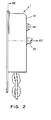
- an electronic sensor for a quick release mechanism, generally designed 12, for a railcar vertical hand brake, generally designated 1, having a housing 14 equipped with a flexible clamp 26 mounted on an inside surface 17 of a wall 16 of the housing 14.
- a release shaft 28 has a member 30 disposed perpendicular to and about the circumference of the release shaft 28.
- a first element 32 is disposed on the member 30, which interposes with the flexible clamp 26 when the release shaft 28 is rotated to both achieve and maintain a full brake release.
- a second element 34 is disposed on the member 30 to engage a projection 24 on a ratchet wheel 22 when an operating shaft 20 of the hand brake 1 is rotated to disengage the first element 32 from the flexible clamp 26 to allow for brake application.
- the electronic sensor 10 comprises a sensing means 36 disposed in a predetermined position for detecting when the release shaft 28 is rotated into a release position, and for communicating a signal, indicating that the hand brake 1 is in the release position.
- a means for activating 38 the sensing means 36 when the release shaft 28 is rotated is disposed in a predetermined position.
- the sensing means 36 is a sensor capable of communicating the signal when the sensor 36 is positioned within a sensitivity range of the activating means 38 when the release shaft 28 is rotated.
- the sensor is disposed on at least one of the member 30 and the housing 14.
- the sensor is disposed on the inside surface 17 of the wall 16 of the housing 14. Also preferred is that the sensor is at least one of a magnetic switch and a Hall effect sensor.
- the means for activating 38 the sensing means 36 is preferably at least one of a magnetically charged part, and a light beam.
- the activating means 38 is a magnetically charged part.
- the magnetically charged part is on at least one of the member 30 and the housing 14.
- the magnetically charged part is preferably on the member 30, and is at least one of a magnet and a ferromagnetic material of a predetermined magnetic field strength.
- the magnetically charged part is a magnet, and is at least one of affixed on and embedded in the first element 32 of the member 30.
- the magnet is embedded in the first element 32 of the member 30.
- an electronic sensor for a quick release mechanism, generally designed 12, for a railcar vertical hand brake, generally designated 1, having a housing 14 equipped with a flexible clamp 26 mounted on an inside surface 17 of a wall 16 of the housing 14.
- a release shaft 28 has a member 30 disposed perpendicular to and about the circumference of the release shaft 28.
- a first element 32 is disposed on the member 30, which interposes with the flexible clamp 26 when the release shaft 28 is rotated to both achieve and maintain a full brake release.
- a second element 34 is disposed on the member 30 to engage a projection 24 on a ratchet wheel 22 when an operating shaft 20 of the hand brake 1 is rotated to disengage the first element 32 from the flexible clamp 26 to allow for brake application.
- the electronic sensor 10 comprises a sensing means 36 disposed in a predetermined position for detecting when the release shaft 28 is rotated into a release position, and for communicating a signal, indicating that the hand brake is in the release position.
- a magnetically charged part 38 is disposed in a predetermined position for activating the sensing means 36 when the release shaft 28 is rotated.
- the sensing means 36 is a sensor capable of communicating a signal when the sensor is positioned within a sensitivity range of the magnetically charged part 38 when the release shaft 28 is rotated.
- the senor is disposed on at least one of the member 30 and the housing 14.
- the sensor is disposed on the inside surface 17 of the wall 16 of the housing 14.
- the sensor is at least one of a magnetic switch and a Hall effect sensor.
- the magnetically charged part 38 can be disposed on at least one of the member 30 and the housing 14.
- the magnetically charged part 38 is disposed on the member 30.
- the magnetically charged part 38 is also at least one of a magnet and a ferromagnetic material of a predetermined magnetic field strength.
- the magnetically charged part 38 is a magnet, and is at least one of affixed on and embedded in the first element 32 of the member 30.
- the magnet is embedded in the first element 32 of the member 30.
- an electronic sensor for a quick release mechanism, generally designed 12, for a railcar vertical hand brake, generally designated 1, having a housing 14 equipped with a flexible clamp 26 mounted on an inside surface 17 of a wall 16 of the housing 14.
- a release shaft 28 has a member 30 disposed perpendicular to and about the circumference of the release shaft 28.
- a first element 32 is disposed on the member 30, which interposes with the flexible clamp 26 when the release shaft 28 is rotated to both achieve and maintain a full brake release.
- a second element 34 is disposed on the member 30 to engage a projection 24 on a ratchet wheel 22 when an operating shaft 20 of the hand brake 1 is rotated to disengage the first element 32 from the flexible clamp 26 to allow for brake application.
- the electronic sensor 10 comprises a sensing means 36 disposed in a predetermined position for detecting when the release shaft 28 is rotated into a release position, and for communicating a signal, indicating that the hand brake 1 is in the release position.
- a light beam 40 is disposed in a predetermined position for activating the sensing means 36 when the release shaft 28 is rotated. Preferably, the light beam 40 radiates perpendicular to the rotational movement of the member 30. The light beam 40 communicates with the sensing means 36.
- the release shaft 28 rotated.
- the first element 32 interposes with the flexible clamp 26, whereby the flexible clamp 26 secures the first element 32.
- the magnet, or activating means 38 is disposed on the first element 32 of the member 30 and suitably situated such that it is simultaneously driven into a position that locates it within the detection range of the sensing means 36.
- the sensing means 36 is the sensor that is disposed on the inside surface 17 of the housing 14 wall 16. The magnet activates the sensor, which outputs and transmits a signal to the train operator through an appropriate electrical interface. This signal notifies the train operator that the hand brake 1 is in the fully released position.
- the operating shaft 20 When brake application is desired, the operating shaft 20 is rotated in such a direction to move the projection 24 on the ratchet wheel 22 into engagement with the second element 34. This movement disengages the first element 32 from the flexible clamp 26, moving the magnet out of the sensor's detection range. Signal transmission ceases, indicating to the train operator that the hand brake 1 is in the brake application position.
Landscapes
- Engineering & Computer Science (AREA)
- Mechanical Engineering (AREA)
- Transportation (AREA)
- Braking Arrangements (AREA)
- Valves And Accessory Devices For Braking Systems (AREA)
- Regulating Braking Force (AREA)
- Braking Elements And Transmission Devices (AREA)
- Rotary Switch, Piano Key Switch, And Lever Switch (AREA)
- Handcart (AREA)
- Electric Propulsion And Braking For Vehicles (AREA)
Abstract
Description
Claims (20)
- An electronic sensor for a quick release mechanism in a railcar vertical hand brake, such hand brake having a housing equipped with a flexible clamp mounted on an inside wall of such housing and a release shaft, such release shaft having a member disposed perpendicular to and about a circumference thereof, a first element is disposed on such member which interposes with such flexible clamp when such release shaft is rotated to both achieve and maintain a full brake release and a second element is disposed on such member to engage a projection on a ratchet wheel when an operating shaft of such hand brake is rotated to disengage such first element from such flexible clamp to allow a brake application, said electronic sensor comprising:(a) a sensing means disposed in a predetermined position for detecting when such release shaft is rotated into a release position and for communicating a signal, indicating that such hand brake is in the release position; and(b) a means disposed in a predetermined position for activating said sensing means when such release shaft is rotated.
- The electronic sensor according to claim 1 wherein said sensing means is a sensor capable of communicating said signal when said sensor is positioned within a sensitivity range of said activating means when said release shaft is rotated.
- The electronic sensor according to claim 2 wherein said sensor is disposed on at least one of such member and such housing.
- The electronic sensor according to claim 3 wherein said sensor is disposed on such housing inside wall surface.
- The electronic sensor according to claim 4 wherein said sensor is at least one of a magnetic switch and a Hall effect sensor.
- The electronic sensor according to claim 1 wherein said activating means is at least one of a magnetically charged part and a light beam.
- The electronic sensor according to claim 6 wherein said activating means is a magnetically charged part.
- The electronic sensor according to claim 7 wherein said magnetically charged part is on at least one of such member and such housing.
- The electronic sensor according to claim 8 wherein said magnetically charged part is on such member.
- The electronic sensor according to claim 9 wherein said magnetically charged part is at least one of a magnet and a ferromagnetic material of a predetermined magnetic field strength.
- The electronic sensor according to claim 10 wherein said magnetically charged part is a magnet.
- The electronic sensor according to claim 11 wherein said magnet is at least one of affixed on and embedded in such first element of such member.
- The electronic sensor according to claim 12 wherein said magnet is embedded in such first element of such member.
- An electronic sensor for a quick release mechanism in a railcar hand brake, such hand brake having a housing equipped with a flexible clamp mounted on an inside wall of such housing and a release shaft, such release shaft having a member disposed perpendicular to and about a circumference thereof, a first element is disposed on such member which interposes with such flexible clamp when such release shaft is rotated to both achieve and maintain a full brake release and a second element is disposed on such member to engage a projection on a ratchet wheel when an operating shaft of such hand brake is rotated to disengage such first element from such flexible clamp to allow a brake application, said electronic sensor comprising:(a) a sensing means disposed in a predetermined position for detecting when such release shaft is rotated into a release position and for communicating a signal, indicating that such hand brake is in the release position; and(b) a magnetically charged part disposed in a predetermined position for activating said sensing means when such release shaft is rotated.
- The electronic sensor according to claim 14 wherein said sensing means is a sensor capable of communicating said signal when said sensor is positioned within a sensitivity range of said magnetically charged part when such release shaft is rotated.
- The electronic sensor according to claim 15 wherein said sensor is disposed on at least one of such member and such housing.
- The electronic sensor according to claim 16 wherein said sensor is at least one of a magnetic switch and a Hall effect sensor.
- The electronic sensor according to claim 14 wherein said magnetically charged part is on at least one of such member and such housing.
- The electronic sensor according to claim 18 wherein said magnetically charged part is a magnet.
- An electronic sensor for a quick release mechanism in a railcar hand brake, such hand brake having a housing equipped with a flexible clamp mounted on an inside wall of such housing and a release shaft, such release shaft having a member disposed perpendicular to and about a circumference thereof, a first element is disposed on such member which interposes with such flexible clamp when such release shaft is rotated to both achieve and maintain a full brake release and a second element is disposed on such member to engage a projection on a ratchet wheel when an operating shaft of such hand brake is rotated to disengage such first element from such flexible clamp to allow a brake application, said electronic sensor comprising:a) a sensing means disposed in a predetermined position for detecting when such release shaft is rotated into a release position and for communicating a signal, indicating that such hand brake is in the release position; and(b) a light beam disposed in a predetermined position for activating said sensing means when such release shaft is rotated.
Applications Claiming Priority (2)
| Application Number | Priority Date | Filing Date | Title |
|---|---|---|---|
| US876337 | 2001-06-07 | ||
| US09/876,337 US6364069B1 (en) | 2001-06-07 | 2001-06-07 | Electronic sensor for a quick release hand brake |
Publications (3)
| Publication Number | Publication Date |
|---|---|
| EP1264752A2 true EP1264752A2 (en) | 2002-12-11 |
| EP1264752A3 EP1264752A3 (en) | 2003-01-22 |
| EP1264752B1 EP1264752B1 (en) | 2004-10-20 |
Family
ID=25367473
Family Applications (1)
| Application Number | Title | Priority Date | Filing Date |
|---|---|---|---|
| EP02291210A Expired - Lifetime EP1264752B1 (en) | 2001-06-07 | 2002-05-16 | Electronic sensor for a quick release railcar hand brake |
Country Status (10)
| Country | Link |
|---|---|
| US (1) | US6364069B1 (en) |
| EP (1) | EP1264752B1 (en) |
| CN (1) | CN1328102C (en) |
| AU (1) | AU782137B2 (en) |
| BR (1) | BRPI0201505B8 (en) |
| CA (1) | CA2382709C (en) |
| DE (1) | DE60201628D1 (en) |
| MX (1) | MXPA02005556A (en) |
| NZ (1) | NZ518559A (en) |
| ZA (1) | ZA200203319B (en) |
Cited By (1)
| Publication number | Priority date | Publication date | Assignee | Title |
|---|---|---|---|---|
| US12429242B2 (en) | 2022-01-18 | 2025-09-30 | Computime Electronics (Shenzhen) Co. Ltd. | Thermostat with detachable dial control |
Families Citing this family (12)
| Publication number | Priority date | Publication date | Assignee | Title |
|---|---|---|---|---|
| US6848754B2 (en) * | 2000-02-18 | 2005-02-01 | Westinghouse Air Brake Technologies Corporation | Automatic application hand brake |
| US6474450B1 (en) * | 2001-06-05 | 2002-11-05 | Westinghouse Air Brake Technologies | Mechanical sensor for a quick release hand brake |
| US6474451B1 (en) * | 2001-08-16 | 2002-11-05 | Honeywell International Inc. | Side tension brake condition sensor |
| US7021430B2 (en) * | 2003-03-25 | 2006-04-04 | Westinghouse Air Brake Technologies Corporation | Release hold mechanism for a hand brake having a quick release mechanism |
| US7156471B2 (en) * | 2004-10-28 | 2007-01-02 | Wabtec Holding Corp. | Two-stage cylinder for applying automatic set and release hand brake |
| US8033236B2 (en) * | 2005-09-16 | 2011-10-11 | Ellcon National, Inc. | Handbrake load indicator |
| US8839915B2 (en) * | 2005-10-18 | 2014-09-23 | Sharma & Associates, Inc. | Railway freight car hand brake sensor |
| US7757825B2 (en) * | 2007-05-30 | 2010-07-20 | Ellcon National, Inc. | Quick release hand brake |
| US8172045B2 (en) * | 2008-09-11 | 2012-05-08 | Ellcon National, Inc. | Remote hand brake |
| US8616341B2 (en) * | 2011-02-16 | 2013-12-31 | Wabtec Holding Corp | Device and method for sensing applied condition of a railroad handbrake |
| US10029713B2 (en) | 2015-01-09 | 2018-07-24 | New York Air Brake, LLC | Rail handbrake with prolonged release |
| RU2746868C2 (en) * | 2017-02-02 | 2021-04-21 | Овинто Квба | Method and the system for controlling the hand brake of a railway car |
Family Cites Families (7)
| Publication number | Priority date | Publication date | Assignee | Title |
|---|---|---|---|---|
| US5738416A (en) * | 1994-07-22 | 1998-04-14 | Westinghouse Air Brake Company | Railway braking apparatus to effect a change in a handbrake |
| US5519299A (en) * | 1994-11-16 | 1996-05-21 | Westinghouse Air Brake Company | Method and apparatus for determining and encoding the position of a reverser handle on a locomotive control stand |
| US5799545A (en) * | 1996-02-20 | 1998-09-01 | Westinghouse Air Brake Company | Ergonomic hand wheel for railway car hand brake |
| US6006868A (en) * | 1996-11-14 | 1999-12-28 | Technical Services And Marketing Inc. | System for monitoring brake status on a rail car |
| US6170619B1 (en) * | 1998-10-29 | 2001-01-09 | Honeywell Inc | Manual hand brake sensor for a railroad car |
| US6237722B1 (en) * | 1998-12-10 | 2001-05-29 | Honeywell International Inc | Railroad handbrake “off” sensor |
| US6364428B1 (en) * | 2000-09-18 | 2002-04-02 | Westinghouse Air Brake Technologies Corporation | Apparatus for a quick release mechanism in a railcar hand brake |
-
2001
- 2001-06-07 US US09/876,337 patent/US6364069B1/en not_active Expired - Lifetime
-
2002
- 2002-04-19 CA CA002382709A patent/CA2382709C/en not_active Expired - Lifetime
- 2002-04-22 AU AU35599/02A patent/AU782137B2/en not_active Ceased
- 2002-04-24 NZ NZ518559A patent/NZ518559A/en unknown
- 2002-04-25 ZA ZA200203319A patent/ZA200203319B/en unknown
- 2002-04-30 BR BRPI0201505A patent/BRPI0201505B8/en not_active IP Right Cessation
- 2002-05-16 EP EP02291210A patent/EP1264752B1/en not_active Expired - Lifetime
- 2002-05-16 DE DE60201628T patent/DE60201628D1/en not_active Expired - Lifetime
- 2002-06-05 MX MXPA02005556A patent/MXPA02005556A/en active IP Right Grant
- 2002-06-05 CN CNB021220921A patent/CN1328102C/en not_active Expired - Fee Related
Cited By (1)
| Publication number | Priority date | Publication date | Assignee | Title |
|---|---|---|---|---|
| US12429242B2 (en) | 2022-01-18 | 2025-09-30 | Computime Electronics (Shenzhen) Co. Ltd. | Thermostat with detachable dial control |
Also Published As
| Publication number | Publication date |
|---|---|
| NZ518559A (en) | 2002-12-20 |
| CA2382709A1 (en) | 2002-12-07 |
| BRPI0201505B8 (en) | 2016-05-31 |
| EP1264752A3 (en) | 2003-01-22 |
| CA2382709C (en) | 2005-03-29 |
| BR0201505B1 (en) | 2013-09-17 |
| CN1390736A (en) | 2003-01-15 |
| US6364069B1 (en) | 2002-04-02 |
| DE60201628D1 (en) | 2004-11-25 |
| AU3559902A (en) | 2002-12-12 |
| CN1328102C (en) | 2007-07-25 |
| BR0201505A (en) | 2003-02-11 |
| EP1264752B1 (en) | 2004-10-20 |
| MXPA02005556A (en) | 2002-12-13 |
| ZA200203319B (en) | 2002-10-29 |
| AU782137B2 (en) | 2005-07-07 |
Similar Documents
| Publication | Publication Date | Title |
|---|---|---|
| US6364069B1 (en) | Electronic sensor for a quick release hand brake | |
| US11850736B2 (en) | Joint assembly | |
| US5358075A (en) | Brake movement and adjustment monitoring device | |
| US20090025506A1 (en) | Vehicle Pedal Controls proof against Misapplication of Accelerator | |
| EP1323605A3 (en) | System and method for aircraft braking system usage monitoring | |
| CA2402889A1 (en) | Brake monitoring system | |
| EP1291311A4 (en) | CONTROL PANEL FOR ELEVATOR | |
| US6170619B1 (en) | Manual hand brake sensor for a railroad car | |
| EP1527904A3 (en) | Loose wheel indicator | |
| US4266633A (en) | Brake wear warning system | |
| EP0632291A3 (en) | Method for measuring wear in the lining of a container provided with a pivoted axle and an opening, and a container | |
| CN112839828B (en) | Sensor device with pivot bearing arrangement | |
| US20020134150A1 (en) | Automatic car tire pressure detecting apparatus | |
| US20070084676A1 (en) | Railway freight car hand brake sensor | |
| JP2004210251A (en) | Manual transmission vehicle shift position detection device | |
| BR0110440A (en) | Device for detecting the position of an elevator car | |
| WO2006085156A3 (en) | Drive unit for x-ray system | |
| EP1275571A3 (en) | Apparatus for operating a vertical wheel hand brake | |
| GB2292429B (en) | Brake wear indicator | |
| WO1996022175A3 (en) | Safety device for electrically driven hand tools, in particular circular and compass saws | |
| KR20030007891A (en) | Method for operating a device for tranporting workpieces for a pressing system | |
| EP3576996B1 (en) | Method and system for monitoring of rail wagon hand brake | |
| PL146163B1 (en) | Apparatus for measuring slip between hoisting rope of a winding machine and associated koepe pulley | |
| KR20180016886A (en) | Military trailer parking brake system | |
| EP1188705A3 (en) | Hose reel control |
Legal Events
| Date | Code | Title | Description |
|---|---|---|---|
| PUAI | Public reference made under article 153(3) epc to a published international application that has entered the european phase |
Free format text: ORIGINAL CODE: 0009012 |
|
| PUAL | Search report despatched |
Free format text: ORIGINAL CODE: 0009013 |
|
| AK | Designated contracting states |
Kind code of ref document: A2 Designated state(s): AT BE CH CY DE DK ES FI FR GB GR IE IT LI LU MC NL PT SE TR |
|
| AX | Request for extension of the european patent |
Free format text: AL;LT;LV;MK;RO;SI |
|
| AK | Designated contracting states |
Kind code of ref document: A3 Designated state(s): AT BE CH CY DE DK ES FI FR GB GR IE IT LI LU MC NL PT SE TR |
|
| AX | Request for extension of the european patent |
Free format text: AL;LT;LV;MK;RO;SI |
|
| RIC1 | Information provided on ipc code assigned before grant |
Free format text: 7B 61H 13/02 A, 7B 60T 13/38 B, 7B 60T 17/08 B, 7B 61H 13/04 B |
|
| 17P | Request for examination filed |
Effective date: 20030304 |
|
| 17Q | First examination report despatched |
Effective date: 20030620 |
|
| AKX | Designation fees paid |
Designated state(s): DE FR GB IT |
|
| GRAP | Despatch of communication of intention to grant a patent |
Free format text: ORIGINAL CODE: EPIDOSNIGR1 |
|
| GRAA | (expected) grant |
Free format text: ORIGINAL CODE: 0009210 |
|
| GRAS | Grant fee paid |
Free format text: ORIGINAL CODE: EPIDOSNIGR3 |
|
| AK | Designated contracting states |
Kind code of ref document: B1 Designated state(s): DE FR GB IT |
|
| PG25 | Lapsed in a contracting state [announced via postgrant information from national office to epo] |
Ref country code: IT Free format text: LAPSE BECAUSE OF FAILURE TO SUBMIT A TRANSLATION OF THE DESCRIPTION OR TO PAY THE FEE WITHIN THE PRESCRIBED TIME-LIMIT;WARNING: LAPSES OF ITALIAN PATENTS WITH EFFECTIVE DATE BEFORE 2007 MAY HAVE OCCURRED AT ANY TIME BEFORE 2007. THE CORRECT EFFECTIVE DATE MAY BE DIFFERENT FROM THE ONE RECORDED. Effective date: 20041020 Ref country code: FR Free format text: LAPSE BECAUSE OF FAILURE TO SUBMIT A TRANSLATION OF THE DESCRIPTION OR TO PAY THE FEE WITHIN THE PRESCRIBED TIME-LIMIT Effective date: 20041020 |
|
| REG | Reference to a national code |
Ref country code: GB Ref legal event code: FG4D |
|
| REG | Reference to a national code |
Ref country code: IE Ref legal event code: FG4D |
|
| REF | Corresponds to: |
Ref document number: 60201628 Country of ref document: DE Date of ref document: 20041125 Kind code of ref document: P |
|
| PG25 | Lapsed in a contracting state [announced via postgrant information from national office to epo] |
Ref country code: DE Free format text: LAPSE BECAUSE OF FAILURE TO SUBMIT A TRANSLATION OF THE DESCRIPTION OR TO PAY THE FEE WITHIN THE PRESCRIBED TIME-LIMIT Effective date: 20050121 |
|
| PGFP | Annual fee paid to national office [announced via postgrant information from national office to epo] |
Ref country code: FR Payment date: 20050511 Year of fee payment: 4 |
|
| PGFP | Annual fee paid to national office [announced via postgrant information from national office to epo] |
Ref country code: DE Payment date: 20050512 Year of fee payment: 4 |
|
| PLBE | No opposition filed within time limit |
Free format text: ORIGINAL CODE: 0009261 |
|
| STAA | Information on the status of an ep patent application or granted ep patent |
Free format text: STATUS: NO OPPOSITION FILED WITHIN TIME LIMIT |
|
| 26N | No opposition filed |
Effective date: 20050721 |
|
| EN | Fr: translation not filed | ||
| PGFP | Annual fee paid to national office [announced via postgrant information from national office to epo] |
Ref country code: GB Payment date: 20070516 Year of fee payment: 6 |
|
| GBPC | Gb: european patent ceased through non-payment of renewal fee |
Effective date: 20080516 |
|
| PG25 | Lapsed in a contracting state [announced via postgrant information from national office to epo] |
Ref country code: GB Free format text: LAPSE BECAUSE OF NON-PAYMENT OF DUE FEES Effective date: 20080516 |