EP1264637A1 - Laboratory microchip device for chemical processing or analysis - Google Patents
Laboratory microchip device for chemical processing or analysis Download PDFInfo
- Publication number
- EP1264637A1 EP1264637A1 EP01113937A EP01113937A EP1264637A1 EP 1264637 A1 EP1264637 A1 EP 1264637A1 EP 01113937 A EP01113937 A EP 01113937A EP 01113937 A EP01113937 A EP 01113937A EP 1264637 A1 EP1264637 A1 EP 1264637A1
- Authority
- EP
- European Patent Office
- Prior art keywords
- well
- reservoir
- microchip
- liquid
- flow
- Prior art date
- Legal status (The legal status is an assumption and is not a legal conclusion. Google has not performed a legal analysis and makes no representation as to the accuracy of the status listed.)
- Granted
Links
- 238000004458 analytical method Methods 0.000 title description 9
- 238000012993 chemical processing Methods 0.000 title 1
- 239000007788 liquid Substances 0.000 claims abstract description 37
- 238000005259 measurement Methods 0.000 claims abstract description 11
- 238000000034 method Methods 0.000 claims description 6
- 230000002572 peristaltic effect Effects 0.000 claims description 6
- 238000009506 drug dissolution testing Methods 0.000 claims description 2
- 238000012544 monitoring process Methods 0.000 claims 1
- 102000004169 proteins and genes Human genes 0.000 claims 1
- 108090000623 proteins and genes Proteins 0.000 claims 1
- 239000013074 reference sample Substances 0.000 claims 1
- 238000007789 sealing Methods 0.000 claims 1
- 239000003153 chemical reaction reagent Substances 0.000 description 14
- 238000005086 pumping Methods 0.000 description 9
- 230000000694 effects Effects 0.000 description 4
- 238000001514 detection method Methods 0.000 description 3
- IJGRMHOSHXDMSA-UHFFFAOYSA-N Atomic nitrogen Chemical compound N#N IJGRMHOSHXDMSA-UHFFFAOYSA-N 0.000 description 2
- 238000005370 electroosmosis Methods 0.000 description 2
- 238000001962 electrophoresis Methods 0.000 description 2
- 239000007789 gas Substances 0.000 description 2
- 239000000126 substance Substances 0.000 description 2
- 102000004190 Enzymes Human genes 0.000 description 1
- 108090000790 Enzymes Proteins 0.000 description 1
- 238000010521 absorption reaction Methods 0.000 description 1
- 230000002411 adverse Effects 0.000 description 1
- 239000003570 air Substances 0.000 description 1
- 239000012080 ambient air Substances 0.000 description 1
- 238000003556 assay Methods 0.000 description 1
- 238000001704 evaporation Methods 0.000 description 1
- 230000008020 evaporation Effects 0.000 description 1
- 239000001307 helium Substances 0.000 description 1
- 229910052734 helium Inorganic materials 0.000 description 1
- SWQJXJOGLNCZEY-UHFFFAOYSA-N helium atom Chemical compound [He] SWQJXJOGLNCZEY-UHFFFAOYSA-N 0.000 description 1
- 238000004519 manufacturing process Methods 0.000 description 1
- 238000012986 modification Methods 0.000 description 1
- 230000004048 modification Effects 0.000 description 1
- 229910052757 nitrogen Inorganic materials 0.000 description 1
- 230000035899 viability Effects 0.000 description 1
Images



Classifications
-
- B—PERFORMING OPERATIONS; TRANSPORTING
- B01—PHYSICAL OR CHEMICAL PROCESSES OR APPARATUS IN GENERAL
- B01L—CHEMICAL OR PHYSICAL LABORATORY APPARATUS FOR GENERAL USE
- B01L3/00—Containers or dishes for laboratory use, e.g. laboratory glassware; Droppers
- B01L3/50—Containers for the purpose of retaining a material to be analysed, e.g. test tubes
- B01L3/502—Containers for the purpose of retaining a material to be analysed, e.g. test tubes with fluid transport, e.g. in multi-compartment structures
- B01L3/5027—Containers for the purpose of retaining a material to be analysed, e.g. test tubes with fluid transport, e.g. in multi-compartment structures by integrated microfluidic structures, i.e. dimensions of channels and chambers are such that surface tension forces are important, e.g. lab-on-a-chip
- B01L3/502715—Containers for the purpose of retaining a material to be analysed, e.g. test tubes with fluid transport, e.g. in multi-compartment structures by integrated microfluidic structures, i.e. dimensions of channels and chambers are such that surface tension forces are important, e.g. lab-on-a-chip characterised by interfacing components, e.g. fluidic, electrical, optical or mechanical interfaces
-
- G—PHYSICS
- G01—MEASURING; TESTING
- G01N—INVESTIGATING OR ANALYSING MATERIALS BY DETERMINING THEIR CHEMICAL OR PHYSICAL PROPERTIES
- G01N35/00—Automatic analysis not limited to methods or materials provided for in any single one of groups G01N1/00 - G01N33/00; Handling materials therefor
- G01N35/10—Devices for transferring samples or any liquids to, in, or from, the analysis apparatus, e.g. suction devices, injection devices
- G01N35/1095—Devices for transferring samples or any liquids to, in, or from, the analysis apparatus, e.g. suction devices, injection devices for supplying the samples to flow-through analysers
-
- B—PERFORMING OPERATIONS; TRANSPORTING
- B01—PHYSICAL OR CHEMICAL PROCESSES OR APPARATUS IN GENERAL
- B01L—CHEMICAL OR PHYSICAL LABORATORY APPARATUS FOR GENERAL USE
- B01L2200/00—Solutions for specific problems relating to chemical or physical laboratory apparatus
- B01L2200/02—Adapting objects or devices to another
- B01L2200/026—Fluid interfacing between devices or objects, e.g. connectors, inlet details
- B01L2200/027—Fluid interfacing between devices or objects, e.g. connectors, inlet details for microfluidic devices
-
- B—PERFORMING OPERATIONS; TRANSPORTING
- B01—PHYSICAL OR CHEMICAL PROCESSES OR APPARATUS IN GENERAL
- B01L—CHEMICAL OR PHYSICAL LABORATORY APPARATUS FOR GENERAL USE
- B01L2300/00—Additional constructional details
- B01L2300/04—Closures and closing means
- B01L2300/046—Function or devices integrated in the closure
-
- B—PERFORMING OPERATIONS; TRANSPORTING
- B01—PHYSICAL OR CHEMICAL PROCESSES OR APPARATUS IN GENERAL
- B01L—CHEMICAL OR PHYSICAL LABORATORY APPARATUS FOR GENERAL USE
- B01L2400/00—Moving or stopping fluids
- B01L2400/04—Moving fluids with specific forces or mechanical means
- B01L2400/0403—Moving fluids with specific forces or mechanical means specific forces
- B01L2400/0415—Moving fluids with specific forces or mechanical means specific forces electrical forces, e.g. electrokinetic
-
- B—PERFORMING OPERATIONS; TRANSPORTING
- B01—PHYSICAL OR CHEMICAL PROCESSES OR APPARATUS IN GENERAL
- B01L—CHEMICAL OR PHYSICAL LABORATORY APPARATUS FOR GENERAL USE
- B01L2400/00—Moving or stopping fluids
- B01L2400/04—Moving fluids with specific forces or mechanical means
- B01L2400/0475—Moving fluids with specific forces or mechanical means specific mechanical means and fluid pressure
- B01L2400/0487—Moving fluids with specific forces or mechanical means specific mechanical means and fluid pressure fluid pressure, pneumatics
-
- G—PHYSICS
- G01—MEASURING; TESTING
- G01N—INVESTIGATING OR ANALYSING MATERIALS BY DETERMINING THEIR CHEMICAL OR PHYSICAL PROPERTIES
- G01N35/00—Automatic analysis not limited to methods or materials provided for in any single one of groups G01N1/00 - G01N33/00; Handling materials therefor
- G01N35/00029—Automatic analysis not limited to methods or materials provided for in any single one of groups G01N1/00 - G01N33/00; Handling materials therefor provided with flat sample substrates, e.g. slides
- G01N2035/00099—Characterised by type of test elements
- G01N2035/00158—Elements containing microarrays, i.e. "biochip"
-
- Y—GENERAL TAGGING OF NEW TECHNOLOGICAL DEVELOPMENTS; GENERAL TAGGING OF CROSS-SECTIONAL TECHNOLOGIES SPANNING OVER SEVERAL SECTIONS OF THE IPC; TECHNICAL SUBJECTS COVERED BY FORMER USPC CROSS-REFERENCE ART COLLECTIONS [XRACs] AND DIGESTS
- Y10—TECHNICAL SUBJECTS COVERED BY FORMER USPC
- Y10T—TECHNICAL SUBJECTS COVERED BY FORMER US CLASSIFICATION
- Y10T436/00—Chemistry: analytical and immunological testing
- Y10T436/11—Automated chemical analysis
Definitions
- the present invention concerns an improved microchip apparatus. More specifically, the present invention concerns a new apparatus for introducing samples and reagents to a microchip.
- microchip type devices for chemical analysis is well known.
- Microchip based analytical instruments are commercially available, such as Agilent's Bio Analyser 2100. In the Bio Analyser samples and reagents are introduced to the microchip manually using a pipette or syringe.
- Figure 1 shows a current microchip type device.
- the sample or reagent 1 is deposited into reservoir 2 located on microchip 3 with syringe 4.
- the sample or reagent is then caused to flow through microchannel 5 with known techniques, such as electrophoresis or electroosmosis.
- a problem with the above device is that the sample/reagent must be manually deposited into the reservoir. Often a microchip will contain many tens of reservoirs, thus this process is time consuming and often inaccurate.
- the present invention overcomes these problems by providing an apparatus in which the sample/reagent is continuously circulated through the reservoir thus maintaining a constant volume of liquid in the reservoir.
- a measurement apparatus comprising: a microchip having a well disposal therein, said well being capable of containing a volume of a liquid, and a microchannel connected to said well and arranged to allow said liquid to flow there through, characterised in that said apparatus further comprises a reservoir disposal externally to said microchip, an input line connecting said reservoir to said well and arranged to allow liquid to flow from said reservoir to said well, an output line connected to said well and arranged to allow liquid to flow from said well, and pump means disposed along said input line and arranged to facilitate said flow of liquid from said reservoir to said well and said flow of liquid from said well in a manner such that the volume of liquid contained within said well remains substantially constant.
- the physical parameters of the reagent are held substantially constant.
- microchip and pumping system 15 comprises microchip 20, pump means 26, external reservoir 24, and input and output lines 28 and 29 respectively.
- Microchip 20 comprises a lower plate 31 and an upper plate 32, which are arranged to form microchannel 25.
- a well 21 is formed in the upper plate.
- the diameter of the reservoir is typically 5mm, however, as will be appreciated, the diameter can be varied according to the specific application.
- a microchip carrier 33 is attached to the upper plate and has side walls 34, which further extend the height of the reservoir.
- the microchip includes a cover plate 22 disposed over the top of the reservoir.
- An O-ring 30 is placed between the cover plate and the side walls 34 of the microchip carrier to from a substantially airtight seal between the cover plate and the microchip carrier.
- the cover plate preferably includes a groove 36 in which the O-ring is placed.
- an inlet aperture 41 and an outlet aperture 42 are disposed within the cover plate so that when lines 28, 29 are inserted, a substantially airtight seal is established between the apertures and the lines. Preferably, this is achieved by using some type of flexible rubber tubing for input and output lines.
- External reservoir 24 which contains a volume reagent or sample is located at a convenient distance from the microchip and includes a lid 45 which when placed on the reservoir forms a substantially airtight seal with the reservoir.
- the lid has disposed therein an output aperture 46 and an input aperture 47. Similar to the arrangements described above for the microchip cover plate, the lid apertures are arranged to receive the input and output lines 28, 29 in such a way as to maintain an air-tight volume within the reservoir.
- a pump means 26 is located along input line 28 and is arranged to pump liquid from the external reservoir 24 to the microchip well 21.
- the pump means is a peristaltic pump, however, as will be appreciated, other types of pumps could be used without departing from the scope of the present invention.
- a single pump can be used to cause liquid to flow from the reservoir to the well and from the well to the reservoir.
- the input line 28 extends further into the microchip well than the output line 29. This arrangement ensures that a minimum volume of liquid is pumped into the well before any liquid can be pumped out of the well and back into the reservoir.
- the input line 28 extends deeper into the external reservoir then the output line 29. This arrangement ensures that liquid from the lower portion of the external reservoir is pumped to the well.
- the overall effect of the arrangement of input and output lines described above is that a constant volume is maintained in the well and that a mixing effect occurs in the external reservoir.
- this mixing effect helps to prevent any setting of the liquid in the reservoir.
- the constant exchange of liquid between the well and the reservoir helps to maintain a constant value of the physical parameters, such as temperature, pH and concentration, of the liquid in the microchip well.
- FIG 3 where parts also appearing in figure 2 bear identical numerical designation, a more detailed view of the microchip and well arrangement is shown in which the input line 28 and output line 29 are extending substantially the same distances into the well.
- FIG. 5a-d show some possible pumping arrangements.
- a single pumps means 26 is used with the microchip 20 shown in figure 2.
- the pump means is preferable a peristaltic pump.
- the peristaltic pump causes liquid to flow from the external reservoir 24 into the microchip 20 and back out of the microchip into the external reservoir.
- the single pump and sealed microchip ensuring a constant volume is maintained in the microchip well.
- two peristaltic pumps 26, 27 are employed with microchip 40 shown in figure 4.
- the first pump 26 operates to pump liquid from the external reservoir to the microchip
- the second pump 27 operates to pump liquid from the microchip to the external reservoir.
- the volume of liquid in the microchip well can be controlled. For example, if both pumps are pumping at the same flow rate, the volume in the microchip well will remain substantially constant. However, if second pump 27 is operating at a higher flow rate than first pump 26, the volume of liquid in the microchip well will decrease.
- a syringe pump 55 is used in replacement of the peristaltic pump 26 of figure 5a.
- pumping is achieved by means of inputting a gas, such as Nitrogen or Helium, under pressure into the external reservoir 24 via a gas inlet line 56.
- a gas such as Nitrogen or Helium
- gas inlet line 56 As pressure increases in the external reservoir, liquid present in the reservoir is forced to flow from the reservoir via line 28 into the microchip and ultimately out of the microchip via line 29.
- microchip 20 comprising a single microchip well 21 with input and output lines 28, 29 and a single microchannel 25.
- Sample and/or reagent is pumped into the microchip well 21 and caused to flow through the microchannel 25 by known methods such as electrophoresis or electroosmosis.
- flow through the microchannel can be driven by a vacuum pump disposed at the end of the microchannel.
- detection point 61 located along microchannel 25 analysis of the sample occurs. Such analysis can be by any one of a variety of known techniques such as fluorescence, absorption, or electrochemical analyses.
- a plurality of microchip wells 60a-60d are disposed on the microchip, each with a microchannel 25a-25d, an input line 28a-28d and an output line 29a-29d respectively. Similar to the arrangement described above for figure 6a, on-chip analysis occurs at detection area 62 located along microchannels 25a-25d.
- an on-chip reference well 71 is disposed on the microchip 20.
- the presence of an on-chip reference allows for real time reference measurements to be taken under virtually the same experimental conditions as the sample measurements, thus improving the overall accuracy of the analysis.
- the microchip shown in figure 6b can be incorporated with a plurality of external reservoirs 24a-24n and pumping means 26 to form an on-line parallel on-chip measurement system.
- Such a system may be used for dissolution testing, a tool well known within the pharmaceutical industry.
- the present invention allows for larger reservoir making the storage of greater quantities of reagents possible.
- the evaporation of liquid on-chip is reduced or eliminated, thus no concentration changes or reagent solutions occur during analysis.
- Reagents can be kept in external reservoirs at defined temperature which is important for cell assays and unstable enzymes. Cells do not need to be handled in a buoyancy adjusting buffer to avoid cell settling over measurement time. Viability and/or fluorescence label intensity of cells can be checked without interruption of a testing run.
Landscapes
- Chemical & Material Sciences (AREA)
- Health & Medical Sciences (AREA)
- General Health & Medical Sciences (AREA)
- Analytical Chemistry (AREA)
- Life Sciences & Earth Sciences (AREA)
- Biochemistry (AREA)
- Physics & Mathematics (AREA)
- General Physics & Mathematics (AREA)
- Immunology (AREA)
- Pathology (AREA)
- Dispersion Chemistry (AREA)
- Hematology (AREA)
- Clinical Laboratory Science (AREA)
- Chemical Kinetics & Catalysis (AREA)
- Automatic Analysis And Handling Materials Therefor (AREA)
Abstract
Description
- The present invention concerns an improved microchip apparatus. More specifically, the present invention concerns a new apparatus for introducing samples and reagents to a microchip.
- The use of microchip type devices for chemical analysis is well known. Microchip based analytical instruments are commercially available, such as Agilent's Bio Analyser 2100. In the Bio Analyser samples and reagents are introduced to the microchip manually using a pipette or syringe.
- Figure 1 shows a current microchip type device. The sample or reagent 1 is deposited into
reservoir 2 located onmicrochip 3 with syringe 4. The sample or reagent is then caused to flow throughmicrochannel 5 with known techniques, such as electrophoresis or electroosmosis. - A problem with the above device is that the sample/reagent must be manually deposited into the reservoir. Often a microchip will contain many tens of reservoirs, thus this process is time consuming and often inaccurate.
- A further problem exists with this current method in that while the last reservoirs on the chip are being filled some of sample/reagent deposited into the first reservoir may have evaporated. This can have the negative effect of altering some of the physical or chemical parameters of the sample/reagent, such as the temperature or pH, ultimately adversely effecting the accuracy of the analytical data.
- It is an object of the present invention to overcome the above-mentioned technical problems.
- The present invention overcomes these problems by providing an apparatus in which the sample/reagent is continuously circulated through the reservoir thus maintaining a constant volume of liquid in the reservoir.
- According to the present invention there is provided a measurement apparatus comprising: a microchip having a well disposal therein, said well being capable of containing a volume of a liquid, and a microchannel connected to said well and arranged to allow said liquid to flow there through, characterised in that said apparatus further comprises a reservoir disposal externally to said microchip, an input line connecting said reservoir to said well and arranged to allow liquid to flow from said reservoir to said well, an output line connected to said well and arranged to allow liquid to flow from said well, and pump means disposed along said input line and arranged to facilitate said flow of liquid from said reservoir to said well and said flow of liquid from said well in a manner such that the volume of liquid contained within said well remains substantially constant.
- Advantageously, by keeping a constant volume in the reservoir, the physical parameters of the reagent are held substantially constant.
- While the principle advantages and features of the invention have been described above, a greater understanding and appreciation of the invention may be obtained by referring to the drawings and detailed description of a preferred embodiments, presented by way of example only, in which;
- Figure 2 shows a schematic of the microchip and pump arrangement;
- Figure 3 shows a more detailed view preferred embodiment of the reservoir area of the microchip shown in figure 2;
- Figure 4 shows an alternative embodiment of the reservoir area of the microchip;
- Figures 5a-5d show a variety of possible pumping arrangements;
- Figure 6a shows a single microchannel and reservoir arrangement on the microchip;
- Figure 6b shows a multiple microchannel and reservoirs arrangement on the microchip;
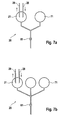
- Figure 7a shows a first possible measurement arrangement on the microchip;
- Figure 7b shows a further possible measurement arrangement on the microchip; and
- Figure 8 shows a schematic of a possible on-line measurement system using the microchip and pumping arrangement of the present invention.
-
- In figure 2 the microchip and
pumping system 15 comprisesmicrochip 20, pump means 26,external reservoir 24, and input andoutput lines - The microchip is of the type known in the art and as such will only be briefly described below.
Microchip 20 comprises alower plate 31 and anupper plate 32, which are arranged to formmicrochannel 25. Awell 21 is formed in the upper plate. The diameter of the reservoir is typically 5mm, however, as will be appreciated, the diameter can be varied according to the specific application. Amicrochip carrier 33 is attached to the upper plate and hasside walls 34, which further extend the height of the reservoir. - According to an aspect of the present invention, the microchip includes a
cover plate 22 disposed over the top of the reservoir. An O-ring 30 is placed between the cover plate and theside walls 34 of the microchip carrier to from a substantially airtight seal between the cover plate and the microchip carrier. The cover plate preferably includes agroove 36 in which the O-ring is placed. - Also disposed within the cover plate are an
inlet aperture 41 and anoutlet aperture 42 arranged to receiveinput line 28 andoutput line 29 respectively.Apertures lines -
External reservoir 24, which contains a volume reagent or sample is located at a convenient distance from the microchip and includes alid 45 which when placed on the reservoir forms a substantially airtight seal with the reservoir. The lid has disposed therein anoutput aperture 46 and aninput aperture 47. Similar to the arrangements described above for the microchip cover plate, the lid apertures are arranged to receive the input andoutput lines - A pump means 26 is located along
input line 28 and is arranged to pump liquid from theexternal reservoir 24 to themicrochip well 21. In this embodiment the pump means is a peristaltic pump, however, as will be appreciated, other types of pumps could be used without departing from the scope of the present invention. - Advantageously, by manufacturing an airtight seal within the reservoir and the well a single pump can be used to cause liquid to flow from the reservoir to the well and from the well to the reservoir.
- In a further aspect of the invention, the
input line 28 extends further into the microchip well than theoutput line 29. This arrangement ensures that a minimum volume of liquid is pumped into the well before any liquid can be pumped out of the well and back into the reservoir. - In yet a further aspect of the present invention, the
input line 28 extends deeper into the external reservoir then theoutput line 29. This arrangement ensures that liquid from the lower portion of the external reservoir is pumped to the well. - The overall effect of the arrangement of input and output lines described above is that a constant volume is maintained in the well and that a mixing effect occurs in the external reservoir. Advantageously, this mixing effect helps to prevent any setting of the liquid in the reservoir.
- Furthermore, the constant exchange of liquid between the well and the reservoir helps to maintain a constant value of the physical parameters, such as temperature, pH and concentration, of the liquid in the microchip well.
- In figure 3, where parts also appearing in figure 2 bear identical numerical designation, a more detailed view of the microchip and well arrangement is shown in which the
input line 28 andoutput line 29 are extending substantially the same distances into the well. - In figure 4, where parts also appearing in figures 2 and 3 bear identical numerical designation, the microchip is shown with the
lid 22 not sealed to the well. In this alternative arrangement the well is open to ambient air pressure. - In this arrangement movement of liquid to the well is caused by a first pump (not shown) and removal of liquid from the well is caused by a second pump (not shown).
- A variety of pumping means can be used with the microchips described in figures 2-4 above. Figures 5a-d show some possible pumping arrangements.
- In figures 5a a single pumps means 26 is used with the
microchip 20 shown in figure 2. The pump means is preferable a peristaltic pump. In operation the peristaltic pump causes liquid to flow from theexternal reservoir 24 into themicrochip 20 and back out of the microchip into the external reservoir. The single pump and sealed microchip ensuring a constant volume is maintained in the microchip well. - In figures 5b two
peristaltic pumps microchip 40 shown in figure 4. Thefirst pump 26 operates to pump liquid from the external reservoir to the microchip, while thesecond pump 27 operates to pump liquid from the microchip to the external reservoir. By controlling the pump rates of the two pumps the volume of liquid in the microchip well can be controlled. For example, if both pumps are pumping at the same flow rate, the volume in the microchip well will remain substantially constant. However, ifsecond pump 27 is operating at a higher flow rate thanfirst pump 26, the volume of liquid in the microchip well will decrease. - In figure 5c a
syringe pump 55 is used in replacement of theperistaltic pump 26 of figure 5a. - In figure 5d pumping is achieved by means of inputting a gas, such as Nitrogen or Helium, under pressure into the
external reservoir 24 via agas inlet line 56. As pressure increases in the external reservoir, liquid present in the reservoir is forced to flow from the reservoir vialine 28 into the microchip and ultimately out of the microchip vialine 29. - As will be appreciated, other pumping means could be used in addition to the examples given above without departing from the scope of the present invention.
- In yet a further embodiment of the present invention, several possible arrangements of microchip wells and microchannels are disclosed.
- In
figure 6a microchip 20 is shown comprising a single microchip well 21 with input andoutput lines single microchannel 25. Sample and/or reagent is pumped into the microchip well 21 and caused to flow through themicrochannel 25 by known methods such as electrophoresis or electroosmosis. Alternatively, flow through the microchannel can be driven by a vacuum pump disposed at the end of the microchannel. Atdetection point 61 located alongmicrochannel 25 analysis of the sample occurs. Such analysis can be by any one of a variety of known techniques such as fluorescence, absorption, or electrochemical analyses. - In figure 6b, a plurality of
microchip wells 60a-60d are disposed on the microchip, each with a microchannel 25a-25d, aninput line 28a-28d and anoutput line 29a-29d respectively. Similar to the arrangement described above for figure 6a, on-chip analysis occurs atdetection area 62 located along microchannels 25a-25d. - Advantageously, by disposing a plurality of wells and channels on a single microchip, simultaneous multiple parallel on-chip detection is possible. The arrangement of wells and channels shown in figure 6b advantageously allows for faster sample throughput, thus reducing both cost and analysis time.
- It is possible to include further features on the microchip. In a further embodiment of the present invention, and as shown in figures 7a and 7b, an on-chip reference well 71 is disposed on the
microchip 20. - Advantageously, the presence of an on-chip reference allows for real time reference measurements to be taken under virtually the same experimental conditions as the sample measurements, thus improving the overall accuracy of the analysis.
- In yet a further possible embodiment of the present invention, and as shown in figure 8, the microchip shown in figure 6b can be incorporated with a plurality of
external reservoirs 24a-24n and pumping means 26 to form an on-line parallel on-chip measurement system. Such a system may be used for dissolution testing, a tool well known within the pharmaceutical industry. - In addition to the above mentioned advantageously, the present invention allows for larger reservoir making the storage of greater quantities of reagents possible. The evaporation of liquid on-chip is reduced or eliminated, thus no concentration changes or reagent solutions occur during analysis. Reagents can be kept in external reservoirs at defined temperature which is important for cell assays and unstable enzymes. Cells do not need to be handled in a buoyancy adjusting buffer to avoid cell settling over measurement time. Viability and/or fluorescence label intensity of cells can be checked without interruption of a testing run.
- Further advantages of the present invention are the ability for online replenishment of the microchip without having to refocus the optics, thus saving time, providing higher throughput, and reducing the danger of microchip being clogged by air bubbles or sedimented cells.
- It is not intended that the present invention be limited to the above embodiments and other modifications and variations are envisaged within the scope of the claims.
Claims (16)
- Measurement apparatus comprising:characterised in that said apparatus further comprises a reservoir (24) disposal externally to said microchip, an input line (28) connecting said reservoir to said well and arranged to allow liquid to flow from said reservoir to said well, an output line (29) connected to said well and arranged to allow liquid to flow from said well, and pump means (26) disposed along said input line and arranged to facilitate said flow of liquid from said reservoir to said well and said flow of liquid from said well in a manner such that the volume of liquid contained within said well remains substantially constant.a microchip (20) having a well (21) disposal therein, said well being capable of containing a volume of a liquid, and a microchannel (25) connected to said well and arranged to allow said liquid to flow there through,
- Apparatus as claimed in Claim 1 wherein said output line (29) is further connected to said reservoir (24).
- Apparatus as claimed in any preceding Claim, wherein a lid (45) is hermetically disposed over said well thereby sealing said well (21) in an airtight manner.
- Apparatus as claimed in any preceding Claim wherein said input line (28) extends further into said well (21) than said output line (29).
- Apparatus as claimed in any preceding Claim wherein said reservoir (24) is hermetically sealed.
- Apparatus as claimed in Claims 2-5, wherein said input line (28) extends further into said reservoir (24) than said output line (29).
- Apparatus as claimed in Claim 2 comprising a further pump means (27) disposed along said output line (29) to facilitate said flow of liquid from said well (21) to said reservoir (24).
- Apparatus as claimed in any preceding Claim, where said pump means (26) and/or said further pump means (27) is a peristaltic pump.
- Apparatus as claimed in Claims 1-7, wherein said pump means (26) and/or said further pump means (27) is a syringe pump.
- Apparatus as claimed in Claims 1-6, where said pump means is gas under pressure.
- Apparatus as claimed in any preceding Claim, wherein said microchip (20) comprises a plurality of wells (21a-21d) and a plurality of microchannels (25a-25d).
- Apparatus as claimed in Claim 11, wherein at least one of said plurality of wells contains a reference sample.
- Apparatus as claimed in any preceding Claim, wherein said liquid is a solution containing proteins.
- Apparatus as claimed in any preceding Claim, wherein said liquid is a solution containing cells.
- The use of said apparatus as claimed in any preceding Claim for on-line process monitoring.
- The use of said apparatus as claimed in Claims 1-14 for dissolution testing.
Priority Applications (3)
| Application Number | Priority Date | Filing Date | Title |
|---|---|---|---|
| EP01113937A EP1264637B1 (en) | 2001-06-07 | 2001-06-07 | Laboratory microchip device and method for chemical analysis |
| DE60118533T DE60118533T2 (en) | 2001-06-07 | 2001-06-07 | Analytical microchip with input and output lines between tub and container |
| US10/121,495 US7186382B2 (en) | 2001-06-07 | 2002-04-12 | Microchip apparatus |
Applications Claiming Priority (1)
| Application Number | Priority Date | Filing Date | Title |
|---|---|---|---|
| EP01113937A EP1264637B1 (en) | 2001-06-07 | 2001-06-07 | Laboratory microchip device and method for chemical analysis |
Publications (2)
| Publication Number | Publication Date |
|---|---|
| EP1264637A1 true EP1264637A1 (en) | 2002-12-11 |
| EP1264637B1 EP1264637B1 (en) | 2006-04-05 |
Family
ID=8177667
Family Applications (1)
| Application Number | Title | Priority Date | Filing Date |
|---|---|---|---|
| EP01113937A Expired - Lifetime EP1264637B1 (en) | 2001-06-07 | 2001-06-07 | Laboratory microchip device and method for chemical analysis |
Country Status (3)
| Country | Link |
|---|---|
| US (1) | US7186382B2 (en) |
| EP (1) | EP1264637B1 (en) |
| DE (1) | DE60118533T2 (en) |
Cited By (1)
| Publication number | Priority date | Publication date | Assignee | Title |
|---|---|---|---|---|
| US11959471B2 (en) | 2021-07-23 | 2024-04-16 | Waters Technologies Corporation | Peristaltic pump having temperature-compensated volumetric delivery |
Families Citing this family (7)
| Publication number | Priority date | Publication date | Assignee | Title |
|---|---|---|---|---|
| US9044774B2 (en) * | 2007-12-18 | 2015-06-02 | Intermolecular, Inc. | Vented combinatorial processing cell |
| US8145434B2 (en) * | 2009-04-10 | 2012-03-27 | Pharmaco-Kinesis Corporation | Method and apparatus for forming a homeostatic loop employing an aptamer biosensor |
| US8870756B2 (en) * | 2010-10-08 | 2014-10-28 | ERBE-USA, Inc. | Hybrid apparatus for fluid supply for endoscopic irrigation and lens cleaning |
| USD750235S1 (en) | 2014-03-19 | 2016-02-23 | ERBE-USA, Inc. | Endoscope connector |
| PL3672470T3 (en) | 2017-08-24 | 2024-06-10 | ERBE-USA, Inc. | DEVICE FOR IMPROVING VISUALIZATION DURING ENDOSCOPIC TREATMENTS |
| US20220228202A1 (en) * | 2021-01-20 | 2022-07-21 | Applied Materials, Inc. | Positive pressure driven flow for multiplexed fluorescence in situ hybridization imaging system |
| DE102021005140A1 (en) | 2021-10-14 | 2023-04-20 | Evorion Biotechnologies Gmbh | Device for controlling the flow of a liquid through a microfluidic connection device |
Citations (2)
| Publication number | Priority date | Publication date | Assignee | Title |
|---|---|---|---|---|
| US5980704A (en) * | 1995-06-07 | 1999-11-09 | David Sarnoff Research Center Inc. | Method and system for inhibiting cross-contamination in fluids of combinatorial chemistry device |
| US6090251A (en) * | 1997-06-06 | 2000-07-18 | Caliper Technologies, Inc. | Microfabricated structures for facilitating fluid introduction into microfluidic devices |
Family Cites Families (5)
| Publication number | Priority date | Publication date | Assignee | Title |
|---|---|---|---|---|
| US5658413A (en) * | 1994-10-19 | 1997-08-19 | Hewlett-Packard Company | Miniaturized planar columns in novel support media for liquid phase analysis |
| US6149787A (en) * | 1998-10-14 | 2000-11-21 | Caliper Technologies Corp. | External material accession systems and methods |
| US6110332A (en) * | 1998-10-26 | 2000-08-29 | The Regents Of The University Of California | T-load microchannel array and fabrication method |
| US6572828B1 (en) * | 1999-07-16 | 2003-06-03 | General Electric Company | Method and apparatus for high-throughput chemical screening |
| US6692708B2 (en) * | 2001-04-05 | 2004-02-17 | Symyx Technologies, Inc. | Parallel reactor for sampling and conducting in situ flow-through reactions and a method of using same |
-
2001
- 2001-06-07 EP EP01113937A patent/EP1264637B1/en not_active Expired - Lifetime
- 2001-06-07 DE DE60118533T patent/DE60118533T2/en not_active Expired - Fee Related
-
2002
- 2002-04-12 US US10/121,495 patent/US7186382B2/en not_active Expired - Fee Related
Patent Citations (2)
| Publication number | Priority date | Publication date | Assignee | Title |
|---|---|---|---|---|
| US5980704A (en) * | 1995-06-07 | 1999-11-09 | David Sarnoff Research Center Inc. | Method and system for inhibiting cross-contamination in fluids of combinatorial chemistry device |
| US6090251A (en) * | 1997-06-06 | 2000-07-18 | Caliper Technologies, Inc. | Microfabricated structures for facilitating fluid introduction into microfluidic devices |
Cited By (1)
| Publication number | Priority date | Publication date | Assignee | Title |
|---|---|---|---|---|
| US11959471B2 (en) | 2021-07-23 | 2024-04-16 | Waters Technologies Corporation | Peristaltic pump having temperature-compensated volumetric delivery |
Also Published As
| Publication number | Publication date |
|---|---|
| DE60118533D1 (en) | 2006-05-18 |
| EP1264637B1 (en) | 2006-04-05 |
| US20020185379A1 (en) | 2002-12-12 |
| US7186382B2 (en) | 2007-03-06 |
| DE60118533T2 (en) | 2006-08-24 |
Similar Documents
| Publication | Publication Date | Title |
|---|---|---|
| US9207249B2 (en) | Automated system for handling microfluidic devices | |
| EP1230028B1 (en) | Method and apparatus for directly sampling a fluid for microfiltration | |
| EP1263533B1 (en) | Microfluidic analysis cartridge | |
| US8252163B2 (en) | Analysis apparatus for capillary electrophoresis | |
| US8512638B2 (en) | Microchip and analyzer using the same | |
| US7163660B2 (en) | Arrangement for taking up liquid analytes | |
| EP2175340B1 (en) | Reagent preparing apparatus, sample processing apparatus and reagent preparing method | |
| AU2004202662B2 (en) | Reducing working fluid dilution in liquid systems | |
| WO2001013127A1 (en) | Analyzing cartridge and liquid feed control device | |
| CN101696916A (en) | Device for analyzing and sieving liquid drops based on integrative sampling probe of chip | |
| US7186382B2 (en) | Microchip apparatus | |
| US7470546B2 (en) | Method and arrangement for taking up a first medium, which is present in a first phase, into a capillary device | |
| WO2018190336A1 (en) | Liquid delivery device and liquid delivery method | |
| CN221117405U (en) | Chip sequencing system for rapid sample injection | |
| CN113376228B (en) | Microfluidic device for ammonia nitrogen detection and application | |
| CN101213023A (en) | Fluid analysis device and method | |
| CN1172183C (en) | A device for introducing liquid into a microanalysis chip | |
| JP2015203664A (en) | Microchannel device | |
| CN214346527U (en) | Microfluid device | |
| US20260056223A1 (en) | Cuvette for analyzing a fluid | |
| KR20260003815A (en) | Cuvette design for use in the cuvette module | |
| CN221199386U (en) | Device for detecting and analyzing formed component | |
| WO2022074730A1 (en) | Sample processing device, sample processing apparatus, and sample processing method | |
| CN121588676A (en) | Methods for mixing fluids |
Legal Events
| Date | Code | Title | Description |
|---|---|---|---|
| PUAI | Public reference made under article 153(3) epc to a published international application that has entered the european phase |
Free format text: ORIGINAL CODE: 0009012 |
|
| AK | Designated contracting states |
Kind code of ref document: A1 Designated state(s): AT BE CH CY DE DK ES FI FR GB GR IE IT LI LU MC NL PT SE TR |
|
| AX | Request for extension of the european patent |
Free format text: AL;LT;LV;MK;RO;SI |
|
| 17P | Request for examination filed |
Effective date: 20030611 |
|
| AKX | Designation fees paid |
Designated state(s): CH DE FR GB LI |
|
| 17Q | First examination report despatched |
Effective date: 20031218 |
|
| RTI1 | Title (correction) |
Free format text: LABORATORY MICROCHIP DEVICE AND METHOD FOR CHEMICAL ANALYSIS |
|
| GRAP | Despatch of communication of intention to grant a patent |
Free format text: ORIGINAL CODE: EPIDOSNIGR1 |
|
| GRAS | Grant fee paid |
Free format text: ORIGINAL CODE: EPIDOSNIGR3 |
|
| GRAJ | Information related to disapproval of communication of intention to grant by the applicant or resumption of examination proceedings by the epo deleted |
Free format text: ORIGINAL CODE: EPIDOSDIGR1 |
|
| GRAP | Despatch of communication of intention to grant a patent |
Free format text: ORIGINAL CODE: EPIDOSNIGR1 |
|
| GRAS | Grant fee paid |
Free format text: ORIGINAL CODE: EPIDOSNIGR3 |
|
| GRAA | (expected) grant |
Free format text: ORIGINAL CODE: 0009210 |
|
| AK | Designated contracting states |
Kind code of ref document: B1 Designated state(s): CH DE FR GB LI |
|
| REG | Reference to a national code |
Ref country code: GB Ref legal event code: FG4D |
|
| REG | Reference to a national code |
Ref country code: CH Ref legal event code: EP |
|
| REF | Corresponds to: |
Ref document number: 60118533 Country of ref document: DE Date of ref document: 20060518 Kind code of ref document: P |
|
| RAP2 | Party data changed (patent owner data changed or rights of a patent transferred) |
Owner name: AGILENT TECHNOLOGIES, INC. |
|
| PLBE | No opposition filed within time limit |
Free format text: ORIGINAL CODE: 0009261 |
|
| STAA | Information on the status of an ep patent application or granted ep patent |
Free format text: STATUS: NO OPPOSITION FILED WITHIN TIME LIMIT |
|
| 26N | No opposition filed |
Effective date: 20070108 |
|
| EN | Fr: translation not filed | ||
| PG25 | Lapsed in a contracting state [announced via postgrant information from national office to epo] |
Ref country code: FR Free format text: LAPSE BECAUSE OF FAILURE TO SUBMIT A TRANSLATION OF THE DESCRIPTION OR TO PAY THE FEE WITHIN THE PRESCRIBED TIME-LIMIT Effective date: 20070309 |
|
| PGFP | Annual fee paid to national office [announced via postgrant information from national office to epo] |
Ref country code: CH Payment date: 20080611 Year of fee payment: 8 |
|
| PG25 | Lapsed in a contracting state [announced via postgrant information from national office to epo] |
Ref country code: FR Free format text: LAPSE BECAUSE OF FAILURE TO SUBMIT A TRANSLATION OF THE DESCRIPTION OR TO PAY THE FEE WITHIN THE PRESCRIBED TIME-LIMIT Effective date: 20060405 |
|
| PGFP | Annual fee paid to national office [announced via postgrant information from national office to epo] |
Ref country code: DE Payment date: 20090604 Year of fee payment: 9 Ref country code: GB Payment date: 20090603 Year of fee payment: 9 |
|
| REG | Reference to a national code |
Ref country code: CH Ref legal event code: PL |
|
| PG25 | Lapsed in a contracting state [announced via postgrant information from national office to epo] |
Ref country code: LI Free format text: LAPSE BECAUSE OF NON-PAYMENT OF DUE FEES Effective date: 20090630 Ref country code: CH Free format text: LAPSE BECAUSE OF NON-PAYMENT OF DUE FEES Effective date: 20090630 |
|
| GBPC | Gb: european patent ceased through non-payment of renewal fee |
Effective date: 20100607 |
|
| PG25 | Lapsed in a contracting state [announced via postgrant information from national office to epo] |
Ref country code: DE Free format text: LAPSE BECAUSE OF NON-PAYMENT OF DUE FEES Effective date: 20110101 |
|
| PG25 | Lapsed in a contracting state [announced via postgrant information from national office to epo] |
Ref country code: GB Free format text: LAPSE BECAUSE OF NON-PAYMENT OF DUE FEES Effective date: 20100607 |