EP1263069A2 - Système de piles à combustible et méthode pour la génération d'énergie électrique à l'aide d'un système de piles à combustible - Google Patents
Système de piles à combustible et méthode pour la génération d'énergie électrique à l'aide d'un système de piles à combustible Download PDFInfo
- Publication number
- EP1263069A2 EP1263069A2 EP02008622A EP02008622A EP1263069A2 EP 1263069 A2 EP1263069 A2 EP 1263069A2 EP 02008622 A EP02008622 A EP 02008622A EP 02008622 A EP02008622 A EP 02008622A EP 1263069 A2 EP1263069 A2 EP 1263069A2
- Authority
- EP
- European Patent Office
- Prior art keywords
- fuel cell
- cell system
- fuel
- energy
- hydrogen
- Prior art date
- Legal status (The legal status is an assumption and is not a legal conclusion. Google has not performed a legal analysis and makes no representation as to the accuracy of the status listed.)
- Granted
Links
- 239000000446 fuel Substances 0.000 title claims abstract description 279
- 238000000034 method Methods 0.000 title claims abstract description 38
- 239000007800 oxidant agent Substances 0.000 claims abstract description 21
- XLYOFNOQVPJJNP-UHFFFAOYSA-N water Substances O XLYOFNOQVPJJNP-UHFFFAOYSA-N 0.000 claims abstract description 11
- 229920005597 polymer membrane Polymers 0.000 claims abstract description 6
- 239000000126 substance Substances 0.000 claims abstract description 6
- 239000001257 hydrogen Substances 0.000 claims description 87
- 229910052739 hydrogen Inorganic materials 0.000 claims description 87
- UFHFLCQGNIYNRP-UHFFFAOYSA-N Hydrogen Chemical compound [H][H] UFHFLCQGNIYNRP-UHFFFAOYSA-N 0.000 claims description 80
- 238000001816 cooling Methods 0.000 claims description 24
- 239000003638 chemical reducing agent Substances 0.000 claims description 14
- QVGXLLKOCUKJST-UHFFFAOYSA-N atomic oxygen Chemical compound [O] QVGXLLKOCUKJST-UHFFFAOYSA-N 0.000 claims description 11
- 239000001301 oxygen Substances 0.000 claims description 11
- 229910052760 oxygen Inorganic materials 0.000 claims description 11
- 239000003054 catalyst Substances 0.000 claims description 6
- 230000015572 biosynthetic process Effects 0.000 claims description 3
- 230000001105 regulatory effect Effects 0.000 claims description 2
- 210000004027 cell Anatomy 0.000 description 182
- 239000003570 air Substances 0.000 description 69
- 230000008569 process Effects 0.000 description 10
- 239000003990 capacitor Substances 0.000 description 8
- 150000002431 hydrogen Chemical class 0.000 description 7
- 239000012528 membrane Substances 0.000 description 5
- 239000003792 electrolyte Substances 0.000 description 4
- 230000002349 favourable effect Effects 0.000 description 4
- 238000005215 recombination Methods 0.000 description 4
- 230000006798 recombination Effects 0.000 description 4
- 238000005265 energy consumption Methods 0.000 description 3
- 230000009286 beneficial effect Effects 0.000 description 2
- 230000000903 blocking effect Effects 0.000 description 2
- 238000007084 catalytic combustion reaction Methods 0.000 description 2
- 238000010586 diagram Methods 0.000 description 2
- 230000000694 effects Effects 0.000 description 2
- 239000010411 electrocatalyst Substances 0.000 description 2
- 239000011888 foil Substances 0.000 description 2
- 230000000977 initiatory effect Effects 0.000 description 2
- 238000005259 measurement Methods 0.000 description 2
- 238000012544 monitoring process Methods 0.000 description 2
- 239000000376 reactant Substances 0.000 description 2
- 230000007704 transition Effects 0.000 description 2
- 238000009423 ventilation Methods 0.000 description 2
- 230000009471 action Effects 0.000 description 1
- 230000006978 adaptation Effects 0.000 description 1
- 239000012080 ambient air Substances 0.000 description 1
- 230000003197 catalytic effect Effects 0.000 description 1
- 210000000170 cell membrane Anatomy 0.000 description 1
- 238000006243 chemical reaction Methods 0.000 description 1
- 238000004140 cleaning Methods 0.000 description 1
- 238000002485 combustion reaction Methods 0.000 description 1
- 238000005056 compaction Methods 0.000 description 1
- 238000010276 construction Methods 0.000 description 1
- 230000001276 controlling effect Effects 0.000 description 1
- 230000008878 coupling Effects 0.000 description 1
- 238000010168 coupling process Methods 0.000 description 1
- 238000005859 coupling reaction Methods 0.000 description 1
- 230000006378 damage Effects 0.000 description 1
- 230000005611 electricity Effects 0.000 description 1
- 238000002474 experimental method Methods 0.000 description 1
- 239000007788 liquid Substances 0.000 description 1
- 238000007726 management method Methods 0.000 description 1
- 230000001404 mediated effect Effects 0.000 description 1
- 230000004044 response Effects 0.000 description 1
- 239000007858 starting material Substances 0.000 description 1
- 230000003068 static effect Effects 0.000 description 1
- 230000001960 triggered effect Effects 0.000 description 1
- 238000011144 upstream manufacturing Methods 0.000 description 1
Images


Classifications
-
- H—ELECTRICITY
- H01—ELECTRIC ELEMENTS
- H01M—PROCESSES OR MEANS, e.g. BATTERIES, FOR THE DIRECT CONVERSION OF CHEMICAL ENERGY INTO ELECTRICAL ENERGY
- H01M8/00—Fuel cells; Manufacture thereof
- H01M8/04—Auxiliary arrangements, e.g. for control of pressure or for circulation of fluids
- H01M8/04298—Processes for controlling fuel cells or fuel cell systems
- H01M8/04694—Processes for controlling fuel cells or fuel cell systems characterised by variables to be controlled
- H01M8/04746—Pressure; Flow
- H01M8/04753—Pressure; Flow of fuel cell reactants
-
- H—ELECTRICITY
- H01—ELECTRIC ELEMENTS
- H01M—PROCESSES OR MEANS, e.g. BATTERIES, FOR THE DIRECT CONVERSION OF CHEMICAL ENERGY INTO ELECTRICAL ENERGY
- H01M8/00—Fuel cells; Manufacture thereof
- H01M8/24—Grouping of fuel cells, e.g. stacking of fuel cells
- H01M8/2457—Grouping of fuel cells, e.g. stacking of fuel cells with both reactants being gaseous or vaporised
-
- H—ELECTRICITY
- H01—ELECTRIC ELEMENTS
- H01M—PROCESSES OR MEANS, e.g. BATTERIES, FOR THE DIRECT CONVERSION OF CHEMICAL ENERGY INTO ELECTRICAL ENERGY
- H01M16/00—Structural combinations of different types of electrochemical generators
- H01M16/003—Structural combinations of different types of electrochemical generators of fuel cells with other electrochemical devices, e.g. capacitors, electrolysers
- H01M16/006—Structural combinations of different types of electrochemical generators of fuel cells with other electrochemical devices, e.g. capacitors, electrolysers of fuel cells with rechargeable batteries
-
- H—ELECTRICITY
- H01—ELECTRIC ELEMENTS
- H01M—PROCESSES OR MEANS, e.g. BATTERIES, FOR THE DIRECT CONVERSION OF CHEMICAL ENERGY INTO ELECTRICAL ENERGY
- H01M8/00—Fuel cells; Manufacture thereof
- H01M8/04—Auxiliary arrangements, e.g. for control of pressure or for circulation of fluids
- H01M8/04007—Auxiliary arrangements, e.g. for control of pressure or for circulation of fluids related to heat exchange
- H01M8/04014—Heat exchange using gaseous fluids; Heat exchange by combustion of reactants
-
- H—ELECTRICITY
- H01—ELECTRIC ELEMENTS
- H01M—PROCESSES OR MEANS, e.g. BATTERIES, FOR THE DIRECT CONVERSION OF CHEMICAL ENERGY INTO ELECTRICAL ENERGY
- H01M8/00—Fuel cells; Manufacture thereof
- H01M8/04—Auxiliary arrangements, e.g. for control of pressure or for circulation of fluids
- H01M8/04007—Auxiliary arrangements, e.g. for control of pressure or for circulation of fluids related to heat exchange
- H01M8/04067—Heat exchange or temperature measuring elements, thermal insulation, e.g. heat pipes, heat pumps, fins
- H01M8/04074—Heat exchange unit structures specially adapted for fuel cell
-
- H—ELECTRICITY
- H01—ELECTRIC ELEMENTS
- H01M—PROCESSES OR MEANS, e.g. BATTERIES, FOR THE DIRECT CONVERSION OF CHEMICAL ENERGY INTO ELECTRICAL ENERGY
- H01M8/00—Fuel cells; Manufacture thereof
- H01M8/04—Auxiliary arrangements, e.g. for control of pressure or for circulation of fluids
- H01M8/04082—Arrangements for control of reactant parameters, e.g. pressure or concentration
- H01M8/04089—Arrangements for control of reactant parameters, e.g. pressure or concentration of gaseous reactants
- H01M8/04104—Regulation of differential pressures
-
- H—ELECTRICITY
- H01—ELECTRIC ELEMENTS
- H01M—PROCESSES OR MEANS, e.g. BATTERIES, FOR THE DIRECT CONVERSION OF CHEMICAL ENERGY INTO ELECTRICAL ENERGY
- H01M8/00—Fuel cells; Manufacture thereof
- H01M8/04—Auxiliary arrangements, e.g. for control of pressure or for circulation of fluids
- H01M8/04298—Processes for controlling fuel cells or fuel cell systems
- H01M8/04313—Processes for controlling fuel cells or fuel cell systems characterised by the detection or assessment of variables; characterised by the detection or assessment of failure or abnormal function
- H01M8/0432—Temperature; Ambient temperature
- H01M8/04365—Temperature; Ambient temperature of other components of a fuel cell or fuel cell stacks
-
- H—ELECTRICITY
- H01—ELECTRIC ELEMENTS
- H01M—PROCESSES OR MEANS, e.g. BATTERIES, FOR THE DIRECT CONVERSION OF CHEMICAL ENERGY INTO ELECTRICAL ENERGY
- H01M8/00—Fuel cells; Manufacture thereof
- H01M8/04—Auxiliary arrangements, e.g. for control of pressure or for circulation of fluids
- H01M8/04298—Processes for controlling fuel cells or fuel cell systems
- H01M8/04694—Processes for controlling fuel cells or fuel cell systems characterised by variables to be controlled
- H01M8/04746—Pressure; Flow
- H01M8/04761—Pressure; Flow of fuel cell exhausts
-
- H—ELECTRICITY
- H01—ELECTRIC ELEMENTS
- H01M—PROCESSES OR MEANS, e.g. BATTERIES, FOR THE DIRECT CONVERSION OF CHEMICAL ENERGY INTO ELECTRICAL ENERGY
- H01M8/00—Fuel cells; Manufacture thereof
- H01M8/04—Auxiliary arrangements, e.g. for control of pressure or for circulation of fluids
- H01M8/04298—Processes for controlling fuel cells or fuel cell systems
- H01M8/04694—Processes for controlling fuel cells or fuel cell systems characterised by variables to be controlled
- H01M8/04746—Pressure; Flow
- H01M8/04783—Pressure differences, e.g. between anode and cathode
-
- H—ELECTRICITY
- H01—ELECTRIC ELEMENTS
- H01M—PROCESSES OR MEANS, e.g. BATTERIES, FOR THE DIRECT CONVERSION OF CHEMICAL ENERGY INTO ELECTRICAL ENERGY
- H01M8/00—Fuel cells; Manufacture thereof
- H01M8/10—Fuel cells with solid electrolytes
- H01M2008/1095—Fuel cells with polymeric electrolytes
-
- H—ELECTRICITY
- H01—ELECTRIC ELEMENTS
- H01M—PROCESSES OR MEANS, e.g. BATTERIES, FOR THE DIRECT CONVERSION OF CHEMICAL ENERGY INTO ELECTRICAL ENERGY
- H01M8/00—Fuel cells; Manufacture thereof
- H01M8/04—Auxiliary arrangements, e.g. for control of pressure or for circulation of fluids
- H01M8/04223—Auxiliary arrangements, e.g. for control of pressure or for circulation of fluids during start-up or shut-down; Depolarisation or activation, e.g. purging; Means for short-circuiting defective fuel cells
- H01M8/04231—Purging of the reactants
-
- H—ELECTRICITY
- H01—ELECTRIC ELEMENTS
- H01M—PROCESSES OR MEANS, e.g. BATTERIES, FOR THE DIRECT CONVERSION OF CHEMICAL ENERGY INTO ELECTRICAL ENERGY
- H01M8/00—Fuel cells; Manufacture thereof
- H01M8/04—Auxiliary arrangements, e.g. for control of pressure or for circulation of fluids
- H01M8/04298—Processes for controlling fuel cells or fuel cell systems
- H01M8/04694—Processes for controlling fuel cells or fuel cell systems characterised by variables to be controlled
- H01M8/04955—Shut-off or shut-down of fuel cells
-
- Y—GENERAL TAGGING OF NEW TECHNOLOGICAL DEVELOPMENTS; GENERAL TAGGING OF CROSS-SECTIONAL TECHNOLOGIES SPANNING OVER SEVERAL SECTIONS OF THE IPC; TECHNICAL SUBJECTS COVERED BY FORMER USPC CROSS-REFERENCE ART COLLECTIONS [XRACs] AND DIGESTS
- Y02—TECHNOLOGIES OR APPLICATIONS FOR MITIGATION OR ADAPTATION AGAINST CLIMATE CHANGE
- Y02E—REDUCTION OF GREENHOUSE GAS [GHG] EMISSIONS, RELATED TO ENERGY GENERATION, TRANSMISSION OR DISTRIBUTION
- Y02E60/00—Enabling technologies; Technologies with a potential or indirect contribution to GHG emissions mitigation
- Y02E60/10—Energy storage using batteries
-
- Y—GENERAL TAGGING OF NEW TECHNOLOGICAL DEVELOPMENTS; GENERAL TAGGING OF CROSS-SECTIONAL TECHNOLOGIES SPANNING OVER SEVERAL SECTIONS OF THE IPC; TECHNICAL SUBJECTS COVERED BY FORMER USPC CROSS-REFERENCE ART COLLECTIONS [XRACs] AND DIGESTS
- Y02—TECHNOLOGIES OR APPLICATIONS FOR MITIGATION OR ADAPTATION AGAINST CLIMATE CHANGE
- Y02E—REDUCTION OF GREENHOUSE GAS [GHG] EMISSIONS, RELATED TO ENERGY GENERATION, TRANSMISSION OR DISTRIBUTION
- Y02E60/00—Enabling technologies; Technologies with a potential or indirect contribution to GHG emissions mitigation
- Y02E60/30—Hydrogen technology
- Y02E60/50—Fuel cells
Definitions
- the invention relates to a method for generating electrical energy by means of a fuel cell system in which one or more Fuel cell blocks are supplied with a fuel and an oxidizer and a conversion of chemical energy into a fuel cell block electrical energy takes place.
- the invention relates to a fuel cell system which one or comprises several fuel cell blocks in which chemical energy is converted into electrical energy Energy is convertible, which can be given to a consumer.
- the electrical Power is scalable, for example in the range between 0.01 and approx. 1 kW, so the same concept for a fuel cell system for different Performance requirements can be used. It is also desirable that a such fuel cell system works largely autonomously.
- Such fuel cell systems can then be used, for example, in floor cleaning devices with their own drive, wheelchairs with electric drive, for portable electricity suppliers or as a starter battery replacement for motor vehicles and use planes.
- the invention has for its object a method for generating to provide electrical energy by means of a fuel cell system, through which the fuel cell system is easy to assemble or a fuel cell system to create which is simply constructed.
- Hydrogen is favorably used as fuel and atmospheric oxygen as oxidizer used, the fuel cell block then polymer membrane fuel cells (PEFC).
- PEFC polymer membrane fuel cells
- a fixed pressure difference between Hydrogen supply and air supply is set.
- this pressure difference in the range between 0.1 and 0.3 bar with the higher Air supply pressure.
- the The fuel cell membrane does not dry out because of the pressure difference exceeds a certain threshold and the other that not water vapor is pushed out of the membrane, since the pressure difference is one falls below a certain threshold.
- air becomes an excess of a fuel cell block provided, for example twice the amount of air that is required as a maximum to ensure optimal implementation in the fuel cells. It can be achieved that the amount of hydrogen, which in a fuel cell block is implemented by the power consumption of the Consumer is controlled so that no control device for the Air supply and the hydrogen supply must be provided.
- the air supply pressure is in the range is set between 1.2 bar and 1.5 bar. This also allows the Keep the fuel cell system's own consumption low because of the excess pressure is kept low.
- the Hydrogen a fuel cell block from a supply via a pressure reducer fed.
- the pressure reducer then sets a predetermined value for the pressure of the hydrogen supplied to the fuel cell block, d. H. this supply pressure can be set in a defined manner. So it's cheap if the outlet pressure of the pressure reducer is fixed, so one to achieve a defined supply.
- the setting of the pressure at the hydrogen supply and the pressure at the air supply and the volume flow of the air supply takes place for a specified system essentially during initial commissioning. in the actual operation in which the fuel cell system emits energy however, these operating points are permanently set and are not changed. It is advantageous if the specifications for setting a working point can be set in order to optimize a fuel cell system, whereby, as mentioned, this adjustability of the setting is not during operation is carried out, but for the overall setting of the system before or during the initial commissioning and then no longer changed.
- a hydrogen discharge via a clocked valve takes place.
- the hydrogen removal can then lock so that the supplied to the fuel cell block Control the amount of hydrogen via the power consumption of a consumer leaves, while an excess of hydrogen can be removed.
- Practice has it shown that the excess amount of hydrogen in the invention Process below 2% of the amount of hydrogen consumed lies. It is then sufficient, approximately every 30 to 60 seconds in short time intervals of about 0.5 seconds, for example, to open the clocked shut-off valve to discharge the excess amount.
- an asymmetrical clock provided for clocking the valve.
- a fuel cell system can be easily formed if a Fuel cell block is cooled by air. For example, to do this Provide the fuel cell block with cooling fins and a fan then cools a fuel cell block.
- This setting device ensures that defined values of the supply of Fuel and oxidizer to form a fuel cell block and thereby in particular the pressure and the volume flow of supplied air and the Pressure of supplied hydrogen is fixed.
- the fuel cell system according to the invention has the same advantages as already explained in connection with the method according to the invention were.
- a cooling device for the fuel cell or blocks which comprises a fan.
- the cooling device can be easily formed when a temperature sensor is on a fuel cell block is arranged and one from the temperature sensor determined temperature is a control variable for the fan. This allows the cooling device from the control of the fuel cell system in the essentially decouple because the temperature sensor is the crucial size provides for temperature control on the fuel cell block.
- the cooling can be designed so that when a certain threshold temperature the fan is turned on while the fan is off below this threshold temperature. Via the temperature sensor, which can also be designed as an emergency switch, the whole Turn off the fuel cell system when a certain, previously set Maximum temperature is exceeded. Such an overtemperature can occur, for example, if the cooling device fails.
- a bimetal temperature switch can also be provided for this purpose is arranged in series with a main switch.
- auxiliary energy source which is the auxiliary energy for commissioning the fuel cell system provides and a switch is provided, by means of which the fuel cell system by absorbing energy from the auxiliary energy source in an energy output operation of a fuel cell block is switchable.
- Fuel cell system itself includes energy consumers, such as an air compressor for supplying air to a fuel cell block and a cooling device. If the fuel cell system is started, i. H. the Commissioning initiated, then these energy consumers be supplied with energy accordingly.
- the auxiliary energy source provided that just provides the "starting energy”.
- the energy delivery company is an energy supply company with respect to an external consumer and also with regard to internal consumers, to whom the electrical energy of the fuel cell block or blocks is provided itself.
- the auxiliary energy source comprises one or more accumulators. Via a battery charger these accumulators can be operated during energy delivery charge. So you provide the auxiliary energy, d. H. Start energy to Start up the fuel system ready. It can be done with the accumulators also achieve that if a consumer is connected, this for a tap electrical energy from the fuel cell system for a limited period of time can, even if not yet in the energy supply operation of the Fuel cell blocks is switched. The consumer can then Take energy from the accumulator. This accumulator operation takes place briefly and time-controlled until the fuel cell system is stable reproducible idle operating state.
- auxiliary energy source can be supplied with energy externally.
- connection sockets are provided to which an external power source can be connected. This allows the fuel cell system give some kind of jump start, for example, if the accumulator is discharged.
- an externally actuable switch for introduction commissioning / decommissioning of the fuel cell system is provided.
- An operator operates the switch to complete the commissioning process to initiate or to initiate the decommissioning process.
- the fuel cell system is in one compact container and in particular closed container is arranged, which provide electrical connections for an external consumer is.
- This container can be designed to be transportable, and the fuel cell system can then be used, for example, as a transportable energy supply unit to which a consumer can be connected can.
- a fuel cell system which is designated as a whole in FIG. 1 by 10 is, at terminals 12 a consumer 14 electrical energy mountable.
- the fuel cell system 10 also includes a fuel cell block 16 Fuel cells 18 (FIG. 2) which stack to form the fuel cell block 16 (Fuel cell stack) are connected. In the fuel cell block 16 chemical energy from the cold combustion of a fuel with a Oxidator converted into electrical energy and the 12 at the terminal Provided consumer 14.
- the fuel cells 18 are, in particular, polymer membrane fuel cells (PEFC), in which the electrolyte is protected by a proton Foil is formed, which in addition to the function of the electrolyte Catalyst carrier for the anodic and cathodic electrocatalysts and separator for the gaseous reactants.
- PEFC polymer membrane fuel cells
- a hydrogen storage 20 is provided for a hydrogen supply, the hydrogen via a pressure reducer 22 and a valve device 24 can be fed to the fuel cell block 16.
- the atmospheric oxygen as an oxidizer is supplied via an air supply device 26 fed to the fuel cell block 16.
- a volume flow measuring device 28 determines the amount of air supplied.
- the pressure of the air supplied can be adjusted.
- the double arrows 1 shows the direction of flow of the air.
- a check valve 32 is arranged, which clocked is controllable, so that the blocking effect can be lifted clocked.
- a recombination catalytic converter 34 is connected downstream of the check valve 32 which hydrogen passed through the check valve 32 with atmospheric oxygen oxidized to water.
- the double arrows starting from the hydrogen storage 20 indicate the direction of flow of the hydrogen.
- the fuel cell block 16 is cooled by means of a cooling device 36, the fuel cell block 16 in particular being air-cooled.
- the Triple arrows in Figure 1 indicate the flow direction for cooling supplied air.
- a measuring device 38 is connected to the fuel cell block 16, which performs a voltage measurement and current measurement.
- This measuring device 38 is connected downstream of a circuit breaker 40 with which a Switch energy delivery of the fuel cell block 16 to the consumer 14 leaves.
- An energy distributor 42 is arranged downstream of the circuit breaker 40. about the air supply device 26 and the cooling device 36 as an internal energy consumer of the fuel cell system 10 supply.
- the circuit breaker 40 is an accumulator 44 as an auxiliary energy source downstream, which controls whether the power distributor 42 with the electrical Energy from the fuel cell block 16 or the accumulator 44 is supplied.
- the accumulator 44 there is an accumulator charging device 46 provided, which in turn during an energy delivery operation of the fuel cell block 16 (the circuit breaker 40 is set so that the Consumer 14 from the fuel cell block 16 with electrical energy is supplied) is rechargeable. It can also be provided that the accumulator 44 can be charged from the outside. This is indicated by the arrow with reference number 48 indicated.
- control device 50 Commissioning and decommissioning of the fuel cell system 10 controllable. This is indicated in FIG. 1 by means of a control line 52.
- the commissioning and Control decommissioning of air supply device 26 this is indicated with the reference numeral 54.
- the commissioning of the Control cooling device 36 this is indicated by reference number 56.
- a control valve 58 can also be controlled by the control device 50 Open or close valve device 24 so as to supply hydrogen to Open or block fuel cell block 16; this is with the reference number 58 indicated.
- circuit breaker 40 can be controlled using the control device 50 control, d. H. in particular whether in the energy supply operation to the consumer 14 is switched or the energy consumers of the fuel cell system 10 (for example air supply device 26, cooling device 36, control device 50, valve device 24) with the auxiliary energy the accumulator 44 must be supplied; this control is through that Reference numeral 60 indicated.
- control device 50 control d. H. in particular whether in the energy supply operation to the consumer 14 is switched or the energy consumers of the fuel cell system 10 (for example air supply device 26, cooling device 36, control device 50, valve device 24) with the auxiliary energy the accumulator 44 must be supplied; this control is through that Reference numeral 60 indicated.
- control device 50 effects the clocked opening of the Check valve 32; this is indicated by reference number 62.
- the structure of the fuel cell system 10 is described below using a Embodiment explained in more detail and its operation explained in more detail.
- the air supply device 26 comprises, as shown in FIG. 2, an air filter 64, to which an air conveyor 68 operated by means of an electric motor 66 (Compaction conveyor) is connected downstream.
- the electric motor 66 is over Connections 70 supplied with electrical energy, the circuit of which Connections 70 are made via the control device 50, specifically in one such that the electric motor is on or off.
- the air conveyor 68 By means of the air conveyor 68 a certain volume flow of the air can be specified, which is supplied to the fuel cell block 16 with atmospheric oxygen as the oxidizer.
- a Pressure sensor 74 arranged by means of which the pressure of the supplied air can be determined. Furthermore, a volume flow measuring sensor is in the feed line 72 76 for determining the air volume flow supplied to the fuel cell block 16 arranged.
- an adjusting valve 80 is arranged, which for example, is manually operable and with which the pressure in the supply line 72 and the discharge line 78 can be adjusted so that volume flow and pressure of the air supply via the air conveyor 68 (air compressor) and the adjustment valve 80 are adjustable in direct dependence and in particular are definable.
- a hydrogen supply 20 has a first one on a hydrogen supply side 82 Hydrogen storage 84 and a second hydrogen storage 86 arranged. These are each via quick couplings 88, 90 to a WasserstorfzuScience Gustav 92 coupled. This in turn is with a relief valve 94 connected, which is particularly manually operable, so that hydrogen can be removed from the fuel cell system. In normal In the operating mode, the expansion valve 94 is closed.
- a pressure reducer 96 is arranged in the hydrogen supply line 92, which is in particular provided with a check valve 98, for example is manually operable.
- the pressure reducer has a pressure sensor 100, by means of which the pressure can be determined and displayed before the pressure is reduced.
- the pressure reducer reduces the pressure of the hydrogen in the supply line 92 to a fixed adjustable value, i. H. after the pressure reducer 96 has the hydrogen in the hydrogen supply line 92 a certain, fixed pressure. This pressure can be over determine a pressure sensor 102 and, if necessary, display it so that it checks can be.
- a safety valve 104 is arranged, via which hydrogen from the Fuel cell system 10 can be removed if, for example, an increase in pressure entry.
- an in particular electromagnetically actuated check valve 106 is arranged in the hydrogen supply line 92 in front of the fuel cell block 16 .
- the safety valve 104 and the check valve 106 form the valve device 24.
- Control ports 108 of the check valve 106 are with the Control device 50 connected, so that the supply of Hydrogen can be blocked or released to the fuel cell system.
- the check valve 106 is controlled so that it is either open or closed is.
- a check valve 114 is arranged in a discharge line 112, which can be actuated electromagnetically, corresponding connections 116 to the Control device 50 are connected. Between the connections 116 and the control device 50 is an asymmetrical clock 118 switched, via which the check valve 114 is controlled independently clocked is and in particular this can be opened clocked in order for a To provide hydrogen relaxation from the fuel cell block 16 forth.
- a check valve is connected downstream of the check valve 114 in the discharge line 112 120 arranged, which is particularly manually operable. through of this adjustment valve 120, the expansion pressure can be adjusted.
- the adjustment valve 120 is followed in the hydrogen discharge line 112 Recombination device 122, on which hydrogen with atmospheric oxygen is converted catalytically to water.
- hydrogen with atmospheric oxygen is converted catalytically to water.
- the only emission of the fuel cell system 10 is therefore water in liquid Form and / or in vapor form.
- the cooling device 36 comprises a fan 124, which by a Motor 126 is driven. This motor in turn is connected via connections 128 powered, these ports 128 by the control device 50 controllable with regard to the provision of electrical energy are.
- the temperature of the fuel cell block 16 is about one or more Temperature sensors 130 determined, and is via a thermal switch 132 then the fan 124 is controlled.
- the control of the control device 50 The connections 128 are essentially only controls with regard to the Power supply for switching the fan 124 on or off need not be provided that the fan 124 to the fuel cell system 10 is fed back, d. H. the control signal to operate the fan 124 comes from the temperature sensor 130 (two-point control).
- a temperature switch for example a bimetal switch which is connected in series to a main switch 134 is switched off, the fuel cell system 10 switches off, d. H. the feeder of hydrogen and air to the fuel cell block 16.
- the temperature control of the fuel cell block 16 via the fan 124 is then via a two-point control, for example, independently of the Control the operation of the fuel cell system 10.
- a positive potential line 136 leads from the fuel cell block 16 to one corresponding plus connection 138 and a corresponding minus potential line 140 to a minus connection 142, these connections form the external connection 12.
- Diode 144 for blocking reverse currents and a fuse 146 are arranged.
- Via a shunt resistor, for example in the negative potential line 140 can with the help of a voltmeter 150 and an ammeter 152 voltage applied to the fuel cell block 16 and that from the fuel cell block Measure 16 delivered current.
- the power supply for the ammeter 152 can be from the control device 50, for example, via connections 128.
- a miniature consumer between the plus potential line 136 and the negative potential line 140 is arranged to stand still of the fuel cell block 16 to prevent polarity reversal of the fuel cells 18.
- the positive potential line 136 can be connected to the circuit breaker 40 Switch positive connection 138, or this connection can be switched off.
- the Circuit breaker 40 is in turn connected to control device 50.
- a capacitor 154 for example an electrolytic capacitor. This capacitor is used during the switching process of the circuit breaker 40, in which a changeover the energy supply to the consumers of the fuel cell system 10 from the accumulator 44 to the fuel cell block 16 itself Ensure energy supply, d. H. capacitor 154 provides one Intermediate energy store for the circuit breaker 40.
- the circuit breaker 40 thus has a first switching position 156 in which the connection between the plus potential line 136 and the plus connection 138 is interrupted and has a second switching position 158, in which this connection is established.
- the positive connection 138 is via a fuse 160 connected to a corresponding positive connection of the accumulator 44, the accumulator can comprise several accumulator blocks.
- the main switch 134 is arranged and designed so that when open Main switch (non-operation of the fuel cell system 10) also in the first switching position 156 of the circuit breaker 40 the connection between the positive connection 138 and the accumulator 44 is interrupted.
- a minus connection 162 of the accumulator 44 is via a connecting line 164 connected to the negative terminal 142.
- Charging sockets 166, 168 can also be provided, which have a Plus connection 170 or a minus connection 162 of the accumulator 44 connected are so that it can be charged from the outside.
- an accumulator charging device 172 is provided, which with the plus terminal 170 and the minus terminal 162 of the accumulator constantly connected is.
- the accumulator can be connected to this accumulator device 172 44 as an auxiliary power source during the "normal operation" of the fuel cell system 10 charge, d. H. when the fuel cell system 10 emits electrical energy.
- the battery charger 172 set so that the battery is only charged when the Voltage of the consumer 14 is below a certain value, so that the accumulator charge does not restrict the operation of the consumer 14.
- a positive terminal 174 of the control device 50 is connected to the positive terminal 138 connected. Furthermore, a minus connection 176 of the control device 50 connected to the negative terminal 142. This ensures that the Control device 50 regardless of switch position 156 or 158 of the circuit breaker 40 is supplied with electrical energy, so that independent whether the energy comes from the accumulator 44 or from the Fuel cell block 16, via the control device 50 of the electric motor 66, the motor 126 and the check valve 106 via the control device 50 are available.
- the control device 50 comprises one Time control device 178, which in particular by a timing relay Switch-on delay is formed. This can delay the pull-in for example, on the order of 10 to 15 seconds if after initiation of the commissioning of the fuel cell system 10 by the Power supply by means of the accumulator 44 a switchover to one Energy supply is to take place by means of the fuel cell block 16, wherein this switching, triggered by the timing device 178, by the circuit breaker 40 is effected.
- This time control device 178 acts on the connections 116, which the clocked check valve 114 is controllable to the ports 128, by means of which the cooling of the fuel cell block 16 can be controlled (on / off) and on the circuit breaker 40.
- the hydrogen supply is immediately and the air supply to the fuel cell block 16 is released while the Turn on the cooling device 36, the timed release of the check valve 114 and the switching of the circuit breaker 40 from the first Switch position 156 to the second switch position 158 with this pull-in delay he follows. This is fixed and especially determined by what time is required to achieve the fixed predetermined air supply To achieve volume flow and the predetermined pressure.
- connection between the plus connection can be made via a switch 180 138 and the control device 50 interrupt.
- This switch is 180 particularly coupled to the main switch 134 so that the power supply the control device 50 by the main switch 134 on and can be switched off.
- FIG. 3 also shows a thermal switch 159, for example a bimetal switch, shown which, when a certain temperature is exceeded Supply of electrical energy to the control device 50 in this way interrupts the air supply, the hydrogen supply to the fuel cell block 16 and the power supply of the control device 50 is blocked.
- a thermal switch 159 for example a bimetal switch, shown which, when a certain temperature is exceeded Supply of electrical energy to the control device 50 in this way interrupts the air supply, the hydrogen supply to the fuel cell block 16 and the power supply of the control device 50 is blocked.
- control device 50 is also provided with a plurality of Provide fuses; in particular, a fuse is provided for the connections 70 182, a fuse 184 for connections 108, a fuse for connections 116 Fuse 186, a fuse 188 for the connections 128 and for the Circuit breaker 40 a fuse 190 is provided.
- the timing device 178 such as a timing relay, is on RC element 192 upstream with a resistor R and a capacitor C.
- the resistor R and the capacitor C are in series.
- the Resistor R is connected via a diode 194, for example a block diode connected to the positive terminal 174.
- a diode 196 for example a block diode arranged so that it is between a relay side Potential point 198 of the diode 194 and an action point 200 between the Resistor R and the capacitor C is connected.
- capacitor 154 has also proven advantageous for the capacitor 154 to have a diode 202 in parallel to reverse currents and the like from the circuit breaker 40 to intercept.
- the fuel cell system 10 functions as follows:
- the control device 50 and the connection 70 of the motor 66 for the air conveyor 68 switched on, so that the fuel cell block 16 is supplied with air. It was previously as described in more detail below, a certain volume flow as Working point set and also a certain pressure of the air supply. There is a delay in reaching this operating point because the Start of the air conveyor 68 (air compressor) has a delay. This delay is, for example, on the order of 5 to 10 Seconds.
- the fuel cell block 16 also Hydrogen is provided as fuel.
- the pressure of the hydrogen supply is preset by means of the pressure reducer 96 and in particular permanently set. The delay in reaching this working point the hydrogen supply to the fuel cell block 16 is opposite the corresponding delay in the air supply is negligible.
- the accumulator 44 supplies the consumer 14 in this switch position with electrical energy.
- an internal switch can also be provided be the accumulator in this state by the consumer 14th disconnects.
- the timing device switches 178 then the circuit breaker 40 so that it is from its first Switch position 156 changes to its second switch position 158.
- connections 116 and 128 are then connected, i. H. the Clocking of the shut-off valve 106 is started, so that excess Hydrogen can be removed from the fuel cell block 16 for water formation and further the cooling device 36 for the fuel cell block 16 in Gear is set in that the motor 126 can be powered.
- Fuel cell block 16 due to the switching of the circuit breaker 40 in the second switch position 158 the energy required for Hydrogen supply, air supply and for the actuation of the cooling.
- the accumulator 44 is via the accumulator charging device 172 charged so that it will be used again during the next commissioning process ready.
- the accumulator 44 thus supplies the auxiliary energy for starting up the Fuel cell system 10, i. H. to start it and to transition into the energy delivery operation.
- a working point in the hydrogen supply and air supply is specified, d. H. preset during the commissioning process Values are reached and secondly the time delay for the switchover the circuit breaker 40 is specified, the commissioning perform automatically until the energy delivery operation, d. H. it takes place a "one-button commissioning" by actuating the externally operable Main switch 134 without a user subsequently intervening from the outside got to.
- the decommissioning of the fuel cell system 10 initiated namely that the main switch 134 is brought into the off position becomes.
- This will power the air supply, the hydrogen supply blocked by the check valve 106 and the circuit breaker 40 in brought to position 156, d. H. the fuel cell block 16 is none Energy and is automatically reduced.
- the Decommissioning is not a time delay by the timing device 178 necessary because the "working point" for non-operation reached immediately by stopping the fuel supply and oxidizer supply is.
- the "normal operation”, i. H. the power operation or energy delivery operation of the fuel cell system 10 according to the invention functions as follows:
- This Working points can be variable in the sense that they are for a particular System to be set in advance to optimize the system. you will be but not changed in operation, d. H. they keep their permanent position.
- the volume flow of the air, in, is set as the supply parameter which this is fed to the fuel cell block 16.
- the setting takes place via the setting of the power of the air conveyor 68.
- the pressure of the air supply to the fuel cell block via the adjusting valve 80 16 fixed.
- there is no air volume control for example on the use of control valves and under the use electronic control devices.
- the pressure to push the air through the fuel cell block 16 is in particular of the order of 1.2 set up to 1.5 bar. Care is still taken to ensure that there is air in excess is present, d. H. that, for example, double the amount of air provided maximum that is required for the catalytic combustion. It can can also be operated with pressures of up to 3 bar.
- the pressure of the hydrogen feed is set 0.1 bar to 0.3 bar lower, on the one hand to dry out the membrane of the fuel cells 18 to prevent and on the other hand a water vapor removal from the To avoid membranes.
- the flow of hydrogen through the hydrogen supply line 92 becomes adjusted dynamically via the energy consumption of the consumer 14, without this having to be regulated by the fuel cell system itself.
- the check valve 116 controlled by the asymmetrical clock 118, periodically open, for example every 30 to 60 seconds at time intervals of approx. 0.5 Seconds.
- the excess amount of hydrogen in the range of less than 2% of the catalytic combustion in the Fuel cell block 16 is the amount of hydrogen consumed.
- the dissipation of thermal power loss from the fuel cell block 16 takes place by means of the cooling device 36, the fuel cell block 16 is provided with cooling fins.
- the Cooling device only two fixed switching temperatures provided are, namely "high temperature” means turning on the fan 124 and “Temperature low” means switching off accordingly. This Temperatures can be determined with the temperature sensor 130.
- the electrical output power of the fuel cell system 10 is solely from the selection of the fuel cell block 16 depending. A fundamental redesign when the target performance fee is changed is not necessary.
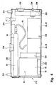
- the fuel cell system 10 is simple integrate into a compact closed container 210 ( Figure 5).
- This The container has a positive connection 212, which is connected to the positive connection 138 connected is.
- a minus connection 214 is provided, which with the Minus connection 142 is connected.
- the main switch 134 is for example formed by a key switch 216 to start up the fuel cell system 10 initiate or effect the decommissioning.
- the hydrogen reservoirs 84 and 86 are arranged inside the container 210, and also the further hydrogen supply with pressure reducer 22 and Valve device 24 to the fuel cell block 16, mediated via corresponding Connections 218.
- ventilation slots 220 on an upper side of the container 210 arranged, via which hydrogen can escape from the container 210, when the safety valve 104 releases it.
- the container 210 has one or more air intake openings 224 to Suck air and air 26 via the air supply device Feed fuel cell block 16.
- an air outlet opening 226 is arranged on the container 210, which is downstream of the adjusting valve 80.
- the electronic circuit to control the commissioning and operation of the fuel cell system added.
- the board 228 carries the control device 50th
- Corresponding display instruments 232 for monitoring are located on a side wall the operation of the fuel cell system 10 arranged, in particular can be determined from voltmeter 150, from ammeter 152 Value, the pressure determined by the pressure sensor 102, that by the pressure sensor 74 determined pressure and the volume flow sensor 76 determined Show volume flow.
- the accumulator 44 is arranged in the housing 230. It can also a socket 234 may be provided, which with the connection sockets 166 and 168 is connected.
- the container 210 with the fuel cell system 10 arranged therein provides a portable power supply unit, from which at most air and Water vapor than in the generation of electrical energy Leak emissions. For example, it can be done with the fuel cell system 10, which is arranged in the container 210, at one Mass of 12 kg to achieve a fully usable output of at least 1000 Wh. In comparison, an accumulator with an output of 800 Wh, of which only 300 Wh can be used, has a mass of 30 to 35 kg.
Landscapes
- Engineering & Computer Science (AREA)
- Life Sciences & Earth Sciences (AREA)
- Sustainable Development (AREA)
- Sustainable Energy (AREA)
- Chemical & Material Sciences (AREA)
- Chemical Kinetics & Catalysis (AREA)
- Electrochemistry (AREA)
- General Chemical & Material Sciences (AREA)
- Manufacturing & Machinery (AREA)
- Combustion & Propulsion (AREA)
- Fuel Cell (AREA)
Applications Claiming Priority (2)
| Application Number | Priority Date | Filing Date | Title |
|---|---|---|---|
| DE10127600 | 2001-05-31 | ||
| DE10127600A DE10127600C2 (de) | 2001-05-31 | 2001-05-31 | Verfahren zur Erzeugung von elektrischer Energie mittels eines Brennstoffzellensystems und Brennstoffzellensystem |
Publications (3)
| Publication Number | Publication Date |
|---|---|
| EP1263069A2 true EP1263069A2 (fr) | 2002-12-04 |
| EP1263069A3 EP1263069A3 (fr) | 2005-08-31 |
| EP1263069B1 EP1263069B1 (fr) | 2014-05-07 |
Family
ID=7687476
Family Applications (1)
| Application Number | Title | Priority Date | Filing Date |
|---|---|---|---|
| EP02008622.9A Expired - Lifetime EP1263069B1 (fr) | 2001-05-31 | 2002-04-17 | Système de piles à combustible et méthode pour la génération d'énergie électrique à l'aide d'un système de piles à combustible |
Country Status (2)
| Country | Link |
|---|---|
| EP (1) | EP1263069B1 (fr) |
| DE (1) | DE10127600C2 (fr) |
Cited By (4)
| Publication number | Priority date | Publication date | Assignee | Title |
|---|---|---|---|---|
| EP1271680A2 (fr) * | 2001-05-31 | 2003-01-02 | Deutsches Zentrum für Luft- und Raumfahrt e.V. | Système de piles à combustible et méthode temporisé pour le démarrage / l'arrêt d'un système de piles à combustible |
| EP2323210A1 (fr) * | 2004-09-17 | 2011-05-18 | Deutsches Zentrum für Luft- und Raumfahrt e.V. | Système de pile à combustible |
| WO2013045043A1 (fr) * | 2011-10-01 | 2013-04-04 | Daimler Ag | Dispositif destiné au stockage d'un combustible gazeux |
| CN114212004A (zh) * | 2021-12-30 | 2022-03-22 | 重庆长安新能源汽车科技有限公司 | 一种燃料电池汽车可续航里程的估算方法 |
Families Citing this family (8)
| Publication number | Priority date | Publication date | Assignee | Title |
|---|---|---|---|---|
| DE10150385B4 (de) * | 2001-10-11 | 2005-12-08 | Ballard Power Systems Ag | Brennstoffzellensystem |
| DE10313437A1 (de) * | 2003-03-26 | 2004-10-07 | Volkswagen Ag | Brennstoffzellensystem und Verfahren zur Steuerung der Energieflüsse in einem Brennstoffzellensystem |
| DE102008020763A1 (de) * | 2008-04-18 | 2009-10-22 | Heliocentris Energiesysteme Gmbh | Peripherie für ein Brennstoffzellensystem |
| DE102008020903A1 (de) | 2008-04-18 | 2009-10-22 | Deutsches Zentrum für Luft- und Raumfahrt e.V. | Flüssigkeitskühlungsvorrichtung für eine Brennstoffzelleneinrichtung und Brennstoffzellensystem |
| DE102011050033B4 (de) | 2011-05-02 | 2013-02-21 | Deutsches Zentrum für Luft- und Raumfahrt e.V. | Bausatz für eine Brennstoffzellenvorrichtung, Brennstoffzellenvorrichtung und Fahrzeug |
| DE102017211610A1 (de) | 2017-07-07 | 2019-01-10 | Audi Ag | Freischalten einer Brennstoffzelle |
| DE102020125732B4 (de) | 2020-10-01 | 2024-03-21 | Deutsches Zentrum für Luft- und Raumfahrt e.V. | Energieaufbereitungsvorrichtung |
| DE102021106069A1 (de) | 2021-03-12 | 2022-09-15 | Deutsches Zentrum für Luft- und Raumfahrt e.V. | Brennstoffzellenvorrichtung für ein Luftfahrzeug, Luftfahrzeug und Verfahren zum Betreiben einer Brennstoffzellenvorrichtung |
Family Cites Families (9)
| Publication number | Priority date | Publication date | Assignee | Title |
|---|---|---|---|---|
| JPS6158173A (ja) * | 1984-08-29 | 1986-03-25 | Shin Kobe Electric Mach Co Ltd | 液体燃料電池 |
| US5290641A (en) * | 1989-10-06 | 1994-03-01 | Fuji Electric Co., Ltd. | Method of controlling operation of fuel cell power supply |
| DE4318818C2 (de) * | 1993-06-07 | 1995-05-04 | Daimler Benz Ag | Verfahren und Vorrichtung zur Bereitstellung von konditionierter Prozessluft für luftatmende Brennstoffzellensysteme |
| DE4322767C2 (de) * | 1993-07-08 | 1995-05-24 | Daimler Benz Ag | Vorrichtung und Verfahren zum Starten eines Brennstoffzellen-Fahrzeugs |
| US5441821A (en) * | 1994-12-23 | 1995-08-15 | Ballard Power Systems Inc. | Electrochemical fuel cell system with a regulated vacuum ejector for recirculation of the fluid fuel stream |
| DE19540824C2 (de) * | 1995-11-02 | 2001-02-22 | Xcellsis Gmbh | Verfahren zur dynamischen Einstellung der Leistung für ein Fahrzeug mit Brennstoffzelle |
| JPH10106598A (ja) * | 1996-09-25 | 1998-04-24 | Ishikawajima Harima Heavy Ind Co Ltd | 燃料電池用改質器の差圧制御方法 |
| DE10010394A1 (de) * | 2000-02-28 | 2001-09-06 | Mannesmann Ag | Brennstoffzelle |
| DE10127599C2 (de) * | 2001-05-31 | 2003-04-24 | Deutsch Zentr Luft & Raumfahrt | Brennstoffzellensystem und Verfahren zur Inbetriebnahme/Außerbetriebnahme eines Brennstoffzellensystems |
-
2001
- 2001-05-31 DE DE10127600A patent/DE10127600C2/de not_active Expired - Lifetime
-
2002
- 2002-04-17 EP EP02008622.9A patent/EP1263069B1/fr not_active Expired - Lifetime
Non-Patent Citations (1)
| Title |
|---|
| None |
Cited By (5)
| Publication number | Priority date | Publication date | Assignee | Title |
|---|---|---|---|---|
| EP1271680A2 (fr) * | 2001-05-31 | 2003-01-02 | Deutsches Zentrum für Luft- und Raumfahrt e.V. | Système de piles à combustible et méthode temporisé pour le démarrage / l'arrêt d'un système de piles à combustible |
| EP1271680A3 (fr) * | 2001-05-31 | 2005-08-31 | Deutsches Zentrum für Luft- und Raumfahrt e.V. | Système de piles à combustible et méthode temporisé pour le démarrage / l'arrêt d'un système de piles à combustible |
| EP2323210A1 (fr) * | 2004-09-17 | 2011-05-18 | Deutsches Zentrum für Luft- und Raumfahrt e.V. | Système de pile à combustible |
| WO2013045043A1 (fr) * | 2011-10-01 | 2013-04-04 | Daimler Ag | Dispositif destiné au stockage d'un combustible gazeux |
| CN114212004A (zh) * | 2021-12-30 | 2022-03-22 | 重庆长安新能源汽车科技有限公司 | 一种燃料电池汽车可续航里程的估算方法 |
Also Published As
| Publication number | Publication date |
|---|---|
| EP1263069A3 (fr) | 2005-08-31 |
| DE10127600C2 (de) | 2003-07-24 |
| EP1263069B1 (fr) | 2014-05-07 |
| DE10127600A1 (de) | 2002-12-12 |
Similar Documents
| Publication | Publication Date | Title |
|---|---|---|
| DE112018007053T5 (de) | In einem Fahrzeug angebrachte Ladevorrichtung und Steuerverfahren für eine in einem Fahrzeug angebrachte Ladevorrichtung | |
| DE112005003104T5 (de) | Hybridbrennstoffzellensystem mit Batterie-Kondensator-Energiespeichersystem | |
| EP1263069B1 (fr) | Système de piles à combustible et méthode pour la génération d'énergie électrique à l'aide d'un système de piles à combustible | |
| EP1227949A1 (fr) | Dispositif de production d'energie electrique avec une cellule electrochimique dans un vehicule et procede permettant d'exploiter ledit dispositif | |
| DE202005009886U1 (de) | Heizgerät für elektrische Speichervorrichtungen für Fahrzeuge | |
| DE102009035101A1 (de) | Verfahren und Vorrichtung zum Starten eines Brennstoffzellenmotors in einem Fahrzeug, der mit einem Ultrakondensator ausgestattet ist | |
| EP2244352A2 (fr) | Installation photovoltaïque dotée d'une batterie et d'une centrale auxiliaire | |
| DE102007026003A1 (de) | Brennstoffzellensystem mit verbesserten Kaltstarteigenschaften sowie Verfahren | |
| DE102011014969A1 (de) | Method of entering and exiting a regenerative/stand-by mode on a fuel cell system where the fuel cell is separated from the regenerative source by a blocking power diode | |
| EP1271680B1 (fr) | Système de piles à combustible et méthode temporisé pour le démarrage / l'arrêt d'un système de piles à combustible | |
| EP1175707B1 (fr) | Dispositif d'alimentation en courant portatif, independant du reseau et n'emettant pas de substances nocives, ainsi que procede pour la production de courant au moyen de ce dispositif | |
| EP0892730B1 (fr) | Procede et dispositif pour augmenter la fiabilite au demarrage d'un moteur a combustion interne | |
| EP1848057A1 (fr) | Système de génération d'électricité comprenant une unité réformeur - pile à combustible et une batterie | |
| EP1205341A2 (fr) | Système de pile à combustible et méthode de fonctionnement pour ce système de pile à combustible | |
| EP1968142B1 (fr) | Contourner und panne d'alimentation d'une pile à combustible | |
| EP1532708B1 (fr) | Pile a combustible a regulation de puissance | |
| EP1848058B1 (fr) | Système d'alimentation comprenant reformeur, pile à combustible et convertisseur continu/continu | |
| EP1588448B1 (fr) | Systeme de pile a combustible et procede pour faire fonctionner une systeme de pile a combustible | |
| EP2293405A1 (fr) | Véhicule de loisir | |
| EP1376724A1 (fr) | Source d'énergie hybride | |
| DE10133580A1 (de) | Elektrisches System | |
| DE102009017458B4 (de) | Verfahren zur Erzeugung und Abgabe von elektrischer Energie an einen Verbraucher | |
| CH652869A5 (de) | Schaltungsanordnung zum laden einer akkumulatorbatterie mit pulsierendem gleichstrom. | |
| DE102004001424B4 (de) | Brennstoffzellenanlage mit einer Kontrolleinheit | |
| DE102020118747A1 (de) | Dauerhaft bei hohen Lastpunkten betriebenes Brennstoffzellensystem |
Legal Events
| Date | Code | Title | Description |
|---|---|---|---|
| PUAI | Public reference made under article 153(3) epc to a published international application that has entered the european phase |
Free format text: ORIGINAL CODE: 0009012 |
|
| AK | Designated contracting states |
Kind code of ref document: A2 Designated state(s): AT BE CH CY DE DK ES FI FR GB GR IE IT LI LU MC NL PT SE TR |
|
| AX | Request for extension of the european patent |
Free format text: AL;LT;LV;MK;RO;SI |
|
| PUAL | Search report despatched |
Free format text: ORIGINAL CODE: 0009013 |
|
| AK | Designated contracting states |
Kind code of ref document: A3 Designated state(s): AT BE CH CY DE DK ES FI FR GB GR IE IT LI LU MC NL PT SE TR |
|
| AX | Request for extension of the european patent |
Extension state: AL LT LV MK RO SI |
|
| 17P | Request for examination filed |
Effective date: 20051116 |
|
| AKX | Designation fees paid |
Designated state(s): AT BE CH CY DE DK ES FI FR GB GR IE IT LI LU MC NL PT SE TR |
|
| GRAP | Despatch of communication of intention to grant a patent |
Free format text: ORIGINAL CODE: EPIDOSNIGR1 |
|
| INTG | Intention to grant announced |
Effective date: 20131203 |
|
| GRAS | Grant fee paid |
Free format text: ORIGINAL CODE: EPIDOSNIGR3 |
|
| GRAA | (expected) grant |
Free format text: ORIGINAL CODE: 0009210 |
|
| AK | Designated contracting states |
Kind code of ref document: B1 Designated state(s): AT BE CH CY DE DK ES FI FR GB GR IE IT LI LU MC NL PT SE TR |
|
| REG | Reference to a national code |
Ref country code: GB Ref legal event code: FG4D Free format text: NOT ENGLISH |
|
| REG | Reference to a national code |
Ref country code: AT Ref legal event code: REF Ref document number: 667292 Country of ref document: AT Kind code of ref document: T Effective date: 20140515 |
|
| REG | Reference to a national code |
Ref country code: IE Ref legal event code: FG4D Free format text: LANGUAGE OF EP DOCUMENT: GERMAN |
|
| REG | Reference to a national code |
Ref country code: DE Ref legal event code: R096 Ref document number: 50215923 Country of ref document: DE Effective date: 20140618 |
|
| REG | Reference to a national code |
Ref country code: NL Ref legal event code: VDEP Effective date: 20140507 |
|
| PG25 | Lapsed in a contracting state [announced via postgrant information from national office to epo] |
Ref country code: CY Free format text: LAPSE BECAUSE OF FAILURE TO SUBMIT A TRANSLATION OF THE DESCRIPTION OR TO PAY THE FEE WITHIN THE PRESCRIBED TIME-LIMIT Effective date: 20140507 Ref country code: GR Free format text: LAPSE BECAUSE OF FAILURE TO SUBMIT A TRANSLATION OF THE DESCRIPTION OR TO PAY THE FEE WITHIN THE PRESCRIBED TIME-LIMIT Effective date: 20140808 Ref country code: FI Free format text: LAPSE BECAUSE OF FAILURE TO SUBMIT A TRANSLATION OF THE DESCRIPTION OR TO PAY THE FEE WITHIN THE PRESCRIBED TIME-LIMIT Effective date: 20140507 |
|
| PG25 | Lapsed in a contracting state [announced via postgrant information from national office to epo] |
Ref country code: ES Free format text: LAPSE BECAUSE OF FAILURE TO SUBMIT A TRANSLATION OF THE DESCRIPTION OR TO PAY THE FEE WITHIN THE PRESCRIBED TIME-LIMIT Effective date: 20140507 Ref country code: SE Free format text: LAPSE BECAUSE OF FAILURE TO SUBMIT A TRANSLATION OF THE DESCRIPTION OR TO PAY THE FEE WITHIN THE PRESCRIBED TIME-LIMIT Effective date: 20140507 |
|
| PG25 | Lapsed in a contracting state [announced via postgrant information from national office to epo] |
Ref country code: PT Free format text: LAPSE BECAUSE OF FAILURE TO SUBMIT A TRANSLATION OF THE DESCRIPTION OR TO PAY THE FEE WITHIN THE PRESCRIBED TIME-LIMIT Effective date: 20140908 |
|
| PG25 | Lapsed in a contracting state [announced via postgrant information from national office to epo] |
Ref country code: DK Free format text: LAPSE BECAUSE OF FAILURE TO SUBMIT A TRANSLATION OF THE DESCRIPTION OR TO PAY THE FEE WITHIN THE PRESCRIBED TIME-LIMIT Effective date: 20140507 |
|
| REG | Reference to a national code |
Ref country code: DE Ref legal event code: R097 Ref document number: 50215923 Country of ref document: DE |
|
| PG25 | Lapsed in a contracting state [announced via postgrant information from national office to epo] |
Ref country code: NL Free format text: LAPSE BECAUSE OF FAILURE TO SUBMIT A TRANSLATION OF THE DESCRIPTION OR TO PAY THE FEE WITHIN THE PRESCRIBED TIME-LIMIT Effective date: 20140507 |
|
| PLBE | No opposition filed within time limit |
Free format text: ORIGINAL CODE: 0009261 |
|
| STAA | Information on the status of an ep patent application or granted ep patent |
Free format text: STATUS: NO OPPOSITION FILED WITHIN TIME LIMIT |
|
| 26N | No opposition filed |
Effective date: 20150210 |
|
| PG25 | Lapsed in a contracting state [announced via postgrant information from national office to epo] |
Ref country code: IT Free format text: LAPSE BECAUSE OF FAILURE TO SUBMIT A TRANSLATION OF THE DESCRIPTION OR TO PAY THE FEE WITHIN THE PRESCRIBED TIME-LIMIT Effective date: 20140507 |
|
| REG | Reference to a national code |
Ref country code: DE Ref legal event code: R097 Ref document number: 50215923 Country of ref document: DE Effective date: 20150210 |
|
| REG | Reference to a national code |
Ref country code: DE Ref legal event code: R082 Ref document number: 50215923 Country of ref document: DE Representative=s name: HOEGER, STELLRECHT & PARTNER PATENTANWAELTE MB, DE |
|
| PG25 | Lapsed in a contracting state [announced via postgrant information from national office to epo] |
Ref country code: LU Free format text: LAPSE BECAUSE OF FAILURE TO SUBMIT A TRANSLATION OF THE DESCRIPTION OR TO PAY THE FEE WITHIN THE PRESCRIBED TIME-LIMIT Effective date: 20150417 Ref country code: MC Free format text: LAPSE BECAUSE OF FAILURE TO SUBMIT A TRANSLATION OF THE DESCRIPTION OR TO PAY THE FEE WITHIN THE PRESCRIBED TIME-LIMIT Effective date: 20140507 |
|
| REG | Reference to a national code |
Ref country code: CH Ref legal event code: PL |
|
| REG | Reference to a national code |
Ref country code: IE Ref legal event code: MM4A |
|
| PG25 | Lapsed in a contracting state [announced via postgrant information from national office to epo] |
Ref country code: CH Free format text: LAPSE BECAUSE OF NON-PAYMENT OF DUE FEES Effective date: 20150430 Ref country code: LI Free format text: LAPSE BECAUSE OF NON-PAYMENT OF DUE FEES Effective date: 20150430 |
|
| REG | Reference to a national code |
Ref country code: FR Ref legal event code: PLFP Year of fee payment: 15 |
|
| PG25 | Lapsed in a contracting state [announced via postgrant information from national office to epo] |
Ref country code: IE Free format text: LAPSE BECAUSE OF NON-PAYMENT OF DUE FEES Effective date: 20150417 |
|
| REG | Reference to a national code |
Ref country code: FR Ref legal event code: PLFP Year of fee payment: 16 |
|
| PGFP | Annual fee paid to national office [announced via postgrant information from national office to epo] |
Ref country code: FR Payment date: 20170322 Year of fee payment: 16 |
|
| PGFP | Annual fee paid to national office [announced via postgrant information from national office to epo] |
Ref country code: GB Payment date: 20170328 Year of fee payment: 16 |
|
| PG25 | Lapsed in a contracting state [announced via postgrant information from national office to epo] |
Ref country code: BE Free format text: LAPSE BECAUSE OF NON-PAYMENT OF DUE FEES Effective date: 20150430 |
|
| PGFP | Annual fee paid to national office [announced via postgrant information from national office to epo] |
Ref country code: DE Payment date: 20170428 Year of fee payment: 16 |
|
| PG25 | Lapsed in a contracting state [announced via postgrant information from national office to epo] |
Ref country code: TR Free format text: LAPSE BECAUSE OF FAILURE TO SUBMIT A TRANSLATION OF THE DESCRIPTION OR TO PAY THE FEE WITHIN THE PRESCRIBED TIME-LIMIT Effective date: 20140507 |
|
| PGFP | Annual fee paid to national office [announced via postgrant information from national office to epo] |
Ref country code: AT Payment date: 20170328 Year of fee payment: 16 |
|
| REG | Reference to a national code |
Ref country code: DE Ref legal event code: R119 Ref document number: 50215923 Country of ref document: DE |
|
| REG | Reference to a national code |
Ref country code: AT Ref legal event code: MM01 Ref document number: 667292 Country of ref document: AT Kind code of ref document: T Effective date: 20180417 |
|
| GBPC | Gb: european patent ceased through non-payment of renewal fee |
Effective date: 20180417 |
|
| PG25 | Lapsed in a contracting state [announced via postgrant information from national office to epo] |
Ref country code: DE Free format text: LAPSE BECAUSE OF NON-PAYMENT OF DUE FEES Effective date: 20181101 Ref country code: AT Free format text: LAPSE BECAUSE OF NON-PAYMENT OF DUE FEES Effective date: 20180417 |
|
| PG25 | Lapsed in a contracting state [announced via postgrant information from national office to epo] |
Ref country code: GB Free format text: LAPSE BECAUSE OF NON-PAYMENT OF DUE FEES Effective date: 20180417 |
|
| PG25 | Lapsed in a contracting state [announced via postgrant information from national office to epo] |
Ref country code: FR Free format text: LAPSE BECAUSE OF NON-PAYMENT OF DUE FEES Effective date: 20180430 |