EP1262917B1 - System and method for demosaicing raw data images with compression considerations - Google Patents
System and method for demosaicing raw data images with compression considerations Download PDFInfo
- Publication number
- EP1262917B1 EP1262917B1 EP01129972A EP01129972A EP1262917B1 EP 1262917 B1 EP1262917 B1 EP 1262917B1 EP 01129972 A EP01129972 A EP 01129972A EP 01129972 A EP01129972 A EP 01129972A EP 1262917 B1 EP1262917 B1 EP 1262917B1
- Authority
- EP
- European Patent Office
- Prior art keywords
- image
- matrix
- compression
- demosaicing
- module
- Prior art date
- Legal status (The legal status is an assumption and is not a legal conclusion. Google has not performed a legal analysis and makes no representation as to the accuracy of the status listed.)
- Expired - Lifetime
Links
Images


Classifications
-
- G—PHYSICS
- G06—COMPUTING; CALCULATING OR COUNTING
- G06T—IMAGE DATA PROCESSING OR GENERATION, IN GENERAL
- G06T3/00—Geometric image transformation in the plane of the image
- G06T3/40—Scaling the whole image or part thereof
- G06T3/4015—Demosaicing, e.g. colour filter array [CFA], Bayer pattern
-
- G—PHYSICS
- G06—COMPUTING; CALCULATING OR COUNTING
- G06T—IMAGE DATA PROCESSING OR GENERATION, IN GENERAL
- G06T9/00—Image coding
- G06T9/007—Transform coding, e.g. discrete cosine transform
-
- H—ELECTRICITY
- H04—ELECTRIC COMMUNICATION TECHNIQUE
- H04N—PICTORIAL COMMUNICATION, e.g. TELEVISION
- H04N23/00—Cameras or camera modules comprising electronic image sensors; Control thereof
- H04N23/80—Camera processing pipelines; Components thereof
- H04N23/84—Camera processing pipelines; Components thereof for processing colour signals
- H04N23/843—Demosaicing, e.g. interpolating colour pixel values
-
- H—ELECTRICITY
- H04—ELECTRIC COMMUNICATION TECHNIQUE
- H04N—PICTORIAL COMMUNICATION, e.g. TELEVISION
- H04N25/00—Circuitry of solid-state image sensors [SSIS]; Control thereof
- H04N25/10—Circuitry of solid-state image sensors [SSIS]; Control thereof for transforming different wavelengths into image signals
- H04N25/11—Arrangement of colour filter arrays [CFA]; Filter mosaics
- H04N25/13—Arrangement of colour filter arrays [CFA]; Filter mosaics characterised by the spectral characteristics of the filter elements
- H04N25/134—Arrangement of colour filter arrays [CFA]; Filter mosaics characterised by the spectral characteristics of the filter elements based on three different wavelength filter elements
-
- H—ELECTRICITY
- H04—ELECTRIC COMMUNICATION TECHNIQUE
- H04N—PICTORIAL COMMUNICATION, e.g. TELEVISION
- H04N2209/00—Details of colour television systems
- H04N2209/04—Picture signal generators
- H04N2209/041—Picture signal generators using solid-state devices
- H04N2209/042—Picture signal generators using solid-state devices having a single pick-up sensor
- H04N2209/045—Picture signal generators using solid-state devices having a single pick-up sensor using mosaic colour filter
- H04N2209/046—Colour interpolation to calculate the missing colour values
Definitions
- the invention relates generally to the field of image processing, and more particularly to a system and method for demosaicing raw data (mosaiced) images.
- Color digital cameras are becoming ubiquitous in the consumer marketplace, partly due to progressive price reductions.
- Color digital cameras typically employ a single optical sensor, either a Charge Coupled Device (CCD) sensor or a Complementary Metal Oxide Semiconductor (CMOS) sensor, to digitally capture a scene of interest.
- CCD Charge Coupled Device
- CMOS Complementary Metal Oxide Semiconductor
- Both CCD and CMOS sensors are only sensitive to illumination. Consequently, these sensors cannot discriminate between different colors.
- a color filtering technique is applied to separate light in terms of base colors, typically red, green and blue.
- a common filtering technique utilizes a color-filter array (CFA), which is overlaid on a sensor array, to separate colors of impinging light in a Bayer pattern.
- the Bayer pattern is a periodic pattern with a period of two different color pixels in each dimension (vertical and horizontal).
- a single period includes either a green pixel and a red pixel, or a blue pixel and a green pixel.
- a single period includes either a green pixel and a blue pixel, or a red pixel and a green pixel. Therefore, the number of green pixels is twice the number of red or blue pixels.
- the reason for the disparity in the number of green pixels is because the human eye is not equally sensitive to all three primary colors. Consequently, more green pixels are needed to create a color image of a scene that will be perceived as a "true color” image.
- the image captured by the sensor is therefore a mosaiced image, also called "raw data" image, where each pixel only holds the value for either red, green or blue.
- the raw data image can then be demosaiced to create a color image by estimating the actual color value, the combination of red, green and blue, for each pixel of the image.
- the color value of a pixel is estimated by using color information from surrounding pixels.
- demosaicing methods there are a number of conventional demosaicing methods to convert a raw data image into a color image.
- Three main common categories of demosaicing methods include interpolation-based methods, feature-based methods, and Bayesian methods.
- the interpolation-based demosaicing methods use simple interpolation formulas to interpolate the color planes separately.
- the interpolation-based demosaicing methods include bi-linear methods, band-limited interpolation methods using sinc () functions, spline interpolation methods, and the like.
- the feature-based demosaicing methods examine local features of a given image at the pixel level, and then interpolate the image accordingly.
- the basic idea of the feature-based methods is to avoid interpolating across edges of features.
- the Bayesian methods attempt to find the most probable color image, given the data, by assuming some prior knowledge of the image structure.
- the image is usually processed through a color-conversion operation and tone mapping, which are part of the image pipe-line.
- the resulting image is then typically stored in the camera using some sort of image compression, such as JPEG or JPEG-like compression schemes, to reduce the size of the image file. Therefore, the digital image that is eventually downloaded from the digital camera by the user is usually a compressed image file.
- US 5,838,818 discloses a demosaicing method in which the mosaiced digital image is processed using a compressing scheme, wherein a raw digital color image is acquired, and the raw image undergoes space transformation and interpolation before being compressed to yield the compressed image. It is described that, before performing the compression algorithm, it is first necessary to transform the image to a luminance/chrominance space. To carry out this transformation, it is first necessary to demosaic the image. Accordingly, demosaicing, color space transformation and compression are performed separately in subsequent steps. Similar prior art is described in WO 01/26359.
- US 5,065,229 describes a method for image compression, in which image data are processed by the sequential steps of interpolation, separating the image into three color planes, and image compression. This document does not make reference to a demosaicing process.
- the compression process is performed subsequent to the demosaicing process, some image enhancements achieved as a result of the demosaicing process may be significantly reduced or completely off-set by the compression process.
- the demosaicing process may create/predict high frequency components in the signal to produce a sharper image.
- the compression process may eliminate or reduce high frequency components of the input image due to the use of quantizers. Therefore, any advantage gained in the demosaicing process may be negated by the compression process.
- the present invention provides a method of demosaicing a mosaiced image according to claim 1 and a system for processing a mosaiced image according to claim 5.
- a system and method for processing mosaiced images utilizes a compression-aware demosaicing process that takes into consideration a subsequent compression process.
- the compression-aware demosaicing process is performed using a compression-considered demosaicing operator that incorporates a color space conversion operator and a frequency-based transformation operator, which are typically associated with the compression process. Consequently, the overall efficiency of the system and method is significantly increased.
- the compression-aware demosaicing process produces artifacts that complement the artifacts produced by the subsequent compression process such that the artifacts are less visible in the final color images, which increases the quality of the final color images.
- a method of processing a mosaiced image in accordance with the present invention includes steps of receiving the mosaiced image, which is a representation of a scene of interest, and processing the mosaiced image using a demosaicing operator on blocks of the mosaiced image to derive a representation of a demosaiced image.
- the demosaicing operator incorporates a frequency-based transformation operator to take into account a subsequent frequency-based compression process.
- the demosaicing operator may also incorporate a color space conversion operator.
- the color space conversion operator may be an operator for converting from the RGB color space to the luminance, red chrominance and blue chrominance ( Yc r c b ) color space.
- the method may also include a step of compressing the representation of the demosaiced image using a frequency-based compression scheme, such as a DCT-based compression scheme or a wavelet-based compression scheme.
- the frequency-based transformation operator incorporated in the demosaicing operator may be a DCT-based transformation operator. In another embodiment, the frequency-based transformation operator is a wavelet-based transformation operator.
- the frequency-based transformation operator, as well as the demosaicing operator, may be matrices.
- the step of processing the mosaiced image is a step of interpolating the mosaiced image using the demosaicing operator, which is derived by defining selected coefficients of transformation-related coefficients as being equal to zero. The selected coefficients may be higher frequency components than remaining coefficients of the transformation-related coefficients.
- the step of processing the mosaiced image is a step of interpolating the mosaiced image using the demosaicing operator, which is derived by defining the transformation-related coefficients as having a predefined probability distribution.
- the predefined probability distribution may be a Normal distribution.
- the demosaicing operator may be derived using the Bayesian rule.
- the representation of the demosaiced image derived from the step of processing the mosaiced image may include a number of image pixel values of the demosaiced image.
- the representation of the demosaiced image includes a number of transformed coefficients of the demosaiced image.
- a system for processing a mosaiced image in accordance with the present invention includes a compression-aware demosaicing module and a compression module.
- the compression-aware demosaicing module is configured to demosaic the mosaiced image to produce a representation of a demosaiced image using a demosaicing operator that incorporates a frequency-based transformation operator.
- the compression module is configured to compress the representation of the demosaiced image to produce a compressed image file by performing a frequency-based compression process.
- the compression-aware demosaicing module and the compression module are embodied in an application specific integrated circuit.
- the demosaicing operator incorporates a color space conversion operator for converting to the Yc b c r color space.
- the frequency-based transformation operator incorporated in the demosaicing operator is a DCT-based transformation operator, and the frequency-based compression process performed by the compression means is a DCT-based compression process.
- the frequency-based transformation operator is a wavelet-based transformation operator, and the frequency-based compression process is a wavelet-based compression process.
- the frequency-based transformation operator, as well as the demosaicing operator may be matrices.
- the demosaicing operator may be derived by defining transformation-related coefficients that are associated with the frequency-based compression process performed by the compression module. In one embodiment, the demosaicing operator is derived by defining selected coefficients of the transformation-related coefficients as being equal to zero. In another embodiment, the demosaicing operator is derived by defining the transformation-related coefficients as having a predefined probability distribution, which may be a Normal distribution. In this embodiment, the demosaicing operator may be derived using the Bayesian rule.
- the representation of the demosaiced image produced by the demosaicing means may include a number of image pixel values of the demosaiced image.
- the representation of the demosaiced image includes a number of transformed coefficients of the demosaiced image.
- an image processing system 100 in accordance with the present invention operates to digitally capture a scene of interest as a mosaiced or raw data image.
- the mosaiced image is then demosaiced and subsequently compressed for storage by the system.
- the image processing system utilizes a compression-aware demosaicing procedure that takes into consideration the fact that the demosaiced image is subsequently compressed.
- the compression-aware demosaicing procedure produces artifacts that complement the artifacts produced by the subsequent compression procedure.
- the overall visual distortion caused by the combined artifacts is significantly reduced, which increases the quality of the final digital image.
- the compression-aware demosaicing procedure performs steps that are typically performed during a compression process, which increases the efficiency of the image processing system to process the captured image.
- the image processing system 100 includes an image capturing unit 102, an image pipeline unit 104, and a storage unit 106.
- the image capturing unit includes a sensor and a color-filter array (CFA).
- the sensor may be a Charge Coupled Device (CCD) sensor, a Complementary Metal Oxide Semiconductor (CMOS) sensor, or other type of photo-sensitive sensor.
- the CFA includes red, blue and green filters arranged in a Bayer filter pattern.
- the CFA may include filters of other colors arranged in a different filter pattern.
- the image capturing unit operates to digitally capture a scene of interest as a mosaiced or raw data image having a color pattern in accordance with the filter pattern of the CFA, e.g., the Bayer pattern.
- the image pipeline unit 104 of the image processing system 100 includes a compression-aware demosaic module 108, a color and tone module 110, and a compression module 112. These modules of the image pipeline unit represent functional blocks and are not necessarily separate components.
- the image pipeline unit is an application specific integrated circuit (ASIC).
- the compression-aware demosaic module 102 of the image pipeline unit 104 operates to demosaic a raw data image into a demosaiced or color image.
- the demosaicing process is performed such that the subsequent compression process performed by the compression module 112 is taken into consideration.
- the components of the compression-aware demosaicing module are shown in Fig. 2.
- the compression-aware demosaicing module includes an image partitioning unit 202, an interpolation unit 204, and a compression-considered demosaicing matrix 206.
- the image partitioning unit operates to partition an input mosaiced image into image blocks, which are equivalent to the blocks that will be operated on by the compression module.
- the image partitioning unit may partition the input mosaiced image into 16 ⁇ 16 pixel image blocks.
- the interpolation unit operates to demosaic each image block of the mosaiced image by multiplying the image block with the compression-considered demosaicing matrix 206 to produce a demosaiced image.
- the compression-considered demosaicing matrix 206 is a demosaicing operator that interpolates a mosaiced image into a demosaiced image.
- the compression-considered demosaicing matrix 206 is derived using a Discrete Cosine Transform (DCT) band-limited approach.
- the interpolation unit can be said to perform a demosaicing process using a DCT band-limited interpolation method.
- the compression-considered demosaicing matrix is derived using a DCT Bayesian approach.
- the interpolation unit can be said to perform a demosaicing process using a DCT Bayesian method.
- the compression-considered demosaicing matrix incorporates a DCT transformation operator, a sampling operator and a color conversion matrix. The operations associated with these operators are conventionally performed as part of the compression process. Since the compression-considered demosaicing matrix incorporates such operators, some or all of the operations associated with these operators need not be performed during the subsequent compression process.
- the compression-considered demosaicing matrix 206 may be stored in a read-only memory (not shown) associated with the image pipeline unit 104. Alternatively, the compression-considered demosaicing matrix may be stored in the storage unit 106.
- the color and tone module 110 of the image pipeline unit operates to perform color and tone enhancements to a demosaiced image from the compression-aware demosaic module 108. These enhancements are conventional operations and thus, are not described herein.
- the color and tone module may perform other conventional image operations such as flare-correction and intermediate color conversion.
- the color and tone module is optional and may be deleted from the image pipeline unit 104.
- the compression module 112 of the image pipeline unit 104 operates to compress the demosaiced image to a compressed image file using a DCT-based compression scheme, such as the JPEG compression scheme.
- the compression module is described herein as using the JPEG compression scheme. For reference, a conventional JPEG compression scheme is briefly described.
- each pixel of the RGB image is transformed into the luminance, red chrominance and blue chrominance ( Yc r c b ) color space.
- the space components of the Yc b c r color space are then sampled, for example, at 4:1:1.
- the Y space component is not altered.
- the c b and c r space components are sampled by a factor of two in each axis.
- the number of c b and c r samples is reduced by a factor of four. This is in line with the human visual perception which is less sensitive to sharp variations in color information.
- each of the Yc b c r color planes is partitioned into disjoint blocks of 8x8.
- Each of these blocks is then processed in the following manner.
- the 8 ⁇ 8 block of scalars is transformed using the DCT into a set of 64 coefficients, which can be arranged as an 8x8 array.
- the set of 64 DCT coefficients is then quantized using a uniform quantizer, which utilizes different quantization step sizes. In general, the higher frequency coefficients are quantized using larger quantization step size.
- Quantization is a non-linear, non-invertible operation.
- the quantized coefficients are then coded using a known coding technique, such as Huffman tables or arithmetic coding.
- the coded data is wrapped in a standard file format.
- JPEG compression procedure assumes that the DCT coefficients that are quantized to a value of greater than zero are concentrated in the low frequencies.
- the Y component space has twice the bandwidth of the c b and c r component spaces.
- all the operations of the procedure are performed on blocks of the image. The operations are performed on 16 ⁇ 16 blocks of the original image, and 8 ⁇ 8 blocks in the transformed/sub-sampled domain. Note that the partitioning of the image into blocks can be done before the color-conversion and sub-sampling, as these steps are point-wise operations that do not interact across block boundaries.
- the compression module 112 of the image pipeline unit 104 includes an image partitioning unit 302, a DCT transformation unit 304, a quantization unit 306, and a coefficient coding unit 308.
- the image partitioning unit performs the image partitioning operation of the JPEG compression scheme. As an example, the image is partitioned into 8x8 blocks of scalars.
- the DCT transformation unit performs the DCT transformation of the compression scheme.
- the quantization unit performs the quantization operation of the compression scheme.
- the coefficient coding unit performs the coding operation of the compression scheme.
- the compression module does not perform the color conversion and sub-sampling operations of the JPEG compression scheme, which have been included in the demosaicing process performed by the compression-aware demosaic module 108.
- the compressed image file produced by the compression module 112 is then stored in the storage unit 106 of the image processing system 100.
- the storage unit may be a conventional storage memory, such as DRAM or flash memory.
- the storage unit may be a drive that interfaces with a removable storage medium, such as a standard computer floppy disk.
- the image capturing unit 102, the image pipeline unit 104, and the storage unit 106 of the system 100 may be included in a single device, such as a digital camera. Alternatively, the image capturing unit may be included in a separate device. In this alternative embodiment, the functions of the image pipeline unit 104 and the storage unit 106 may be performed by a computer.
- the compression-aware demosaic module 108 of the image pipeline unit 104 performs a DCT band-limited interpolation using the compression-considered demosaicing matrix to demosaic raw data images.
- the compression-considered demosaicing matrix is derived by taking into consideration the band-limiting effect of the subsequent DCT-based compression process performed by the compression module 112.
- the DCT band-limited interpolation method essentially solves the problem of how to effectively interpolate a signal from its samples, when the signal is known to be band-limited in the DCT domain.
- the problem and its solution are described herein mathematically. To make the explanation more lucid, the description deals with one-dimensional signals. Extensions to the two-dimensional case with three color components will be described further below.
- the transformation matrix [ T ] is a frequency-based transformation operator. Note that [ T ] is unitary and real.
- the band-limitedness of the DCT coefficients is assumed on the DCT of the image when in Yc b c r color space.
- a 3x3 transformation matrix from RGB values to Yc b c r values is needed.
- the transformation matrix can be readily defined. In general, the transformation matrix will depend on the RGB domain of the image.
- RGB values are assumed to be in the range [0,1]
- the offset of the transformation is ignored, and the color transformation matrix from RGB to Yc b c r will be denoted as [ C r2y ].
- the inverse transformation will be denoted as [ C y2r ].
- These color transformation matrices are color space conversion operators that can transform signals between an RGB color space and a Yc b c r color space.
- the compression-considered demosaicing matrix 206 is thus given by: [ [ S ] [ C y 2 r ] [ T ] ′ ] ⁇ 1 , which is the inverse of the matrix [ S ][ C y 2 r ][ T ] t from the equation in the problem (14).
- the expression "inverse of a matrix” is either a direct inverse or pseudo-inverse of the matrix.
- the expression “inverting a matrix” refers to deriving the inverse of the matrix by either direct inverse or pseudo-inverse.
- the unconstrained problem (14) has substituted the problem of finding x ⁇ ⁇ D k o with the problem of finding a set of coefficients.
- the problem can be solved using minimum-norm solution, least-squares solution, or exact inversion.
- the column-ordering of the image can be considered.
- the column order of a matrix can be obtained by concatenating the columns of the matrix to form a vector.
- each color-plane can be ordered as one column vector.
- the DCT since the DCT is a separable transform, the DCT can be applied first to rows and then to columns, or vice versa.
- the transformation matrix on a column-order version of the matrix can easily be defined.
- the last implementation issue involves the frequency of the input signal.
- a one-dimensional signal has only one-linear axis of frequency and the frequency is a scalar.
- the issue of frequency for a one-dimensional signal is straightforward.
- the issue of frequency is more complex, which is now described.
- L 2 norm : A ( k , l ) 0 for k 2 + l 2 > k 0 .
- L ⁇ norm : A ( k , l ) 0 for max ( k , l ) > k 0 .
- the expressions (16), (17), and (18) are illustrated in Fig.
- DCT coefficients of a two-dimensional signal are presented as a two-dimensional set of scalars.
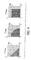
- the DCT coefficients are shown in Fig. 4 as cells in an 8 ⁇ 8 grid 402, where each cell corresponds to one coefficient.
- the non-shaded cells correspond to the DCT coefficients that have been assumed to be zero.
- the remaining DCT coefficients are shown as shaded cells.
- the band-limitedness depends on the norm used.
- the cells that are intersected by the boundary between the shaded region and the non-shaded region should be decided as either shaded or non-shaded cells. Alternatively, these intersected cells can be decided using strict inequality for the range.
- the L 1 norm is found to be more appropriate, due the manner in which the Y component is sampled and the fact that the G component of RGB color space corresponds best to the Y component of Yc r c b color space.
- the compression-considered demosaicing matrix 206 is generated by a separate system and then programmed into the image processing system 100.
- a matrix generating system 500 in accordance with the first embodiment is shown.
- the matrix generation system is configured to generate the compression-considered demosaicing matrix, as defined by expression (15).
- the system of Fig. 5 includes a matrix transposing module 502, a multiplication module 504 and a matrix inverting modules 506.
- the modules 502-506 may be implemented in any combination of hardware, firmware and software, these modules are preferably embodied in the matrix generating system as a software program that performs the functions of the modules 502-506 when executed by a processor (not shown).
- the matrix transposing module 502 of the matrix generation system 500 receives an input matrix [ T ], which is the DCT transformation matrix.
- the matrix transposing module then transposes the received matrix [ T ] to output a matrix [ T ] t , which is transmitted to the multiplication module 504.
- the multiplication module 504 receives input matrices [ S ] and the [ C r2y ] and the output matrix [ T ] t from the matrix transposing module 502.
- the input matrix [ S ] is the sampling matrix.
- the input matrix [ C r2y ] is the color transformation matrix.
- the multiplication module then multiplies the three received matrices in the order illustrated in Fig.
- the compression-aware demosaic module 108 of the image pipeline unit 104 performs a DCT Bayesian demosaicing process using the compression-considered demosaicing matrix 206 to demosaic raw data images.
- the compression-considered demosaicing matrix is derived by assuming some a priori knowledge about the probability distribution of the DCT coefficients.
- the DCT Bayesian approach method associates a probability distribution function with each DCT coefficient. Furthermore, the DCT Bayesian approach method assumes that the coefficients are jointly Normal, with mean vector ⁇ c and covariance matrix [ R c ], or expressed mathematically: z ⁇ c ⁇ ( [ T ] [ C r 2 y ] x ⁇ ) ⁇ N ( ⁇ ⁇ c , [ R c ] ) .
- the DCT Bayesian approach uses an additive noise model to formulate the reconstruction problem.
- the above additive noise model is appropriate since it is natural to assume the measurements are noisy.
- x ⁇ arg max x ⁇ ⁇ Pr ( y ⁇ / x ⁇ ) Pr ( x ⁇ ) ⁇ .
- the assumption about the Gaussian model for noise is incorporated with the Gaussian model for the coefficients.
- Pr ( x ⁇ ) Pr ( [ C y 2 r ] [ T ] ′ z ⁇ c ) ⁇ N ( [ C y 2 r ] [ T ] ′ ⁇ ⁇ c , [ C y 2 r ] [ T ] ′ [ R c ] [ T ] [ C y 2 r ] ′ ) ⁇ N ( ⁇ ⁇ x , [ R x ] ) .
- log ( Pr ( x ⁇ ) ) c ⁇ ( x ⁇ ⁇ ⁇ ⁇ x ) ′ [ R x ] ⁇ 1 ( x ⁇ ⁇ ⁇ x ) .
- the compression-considered demosaicing matrix 206 is thus given by: [ Q ] ⁇ 1 [ S ] t [ R n ] ⁇ 1 .
- the term [ Q ] -1 [ R x ] -1 ⁇ x of equation (46) represents bias. Assuming known noise and known distribution of the coefficients, equation (46) gives a closed form solution to find the most probable x ⁇ , given the measurements y ⁇ .
- noise can be assumed as needed. If the noise is assumed to be very low, the resulting image at the sampling points is essentially forced to be exactly equal to the sample values. However, if the noise is assumed to be high, the values at the sampling points are regarded merely as recommended values to the algorithm. Note that noise can be estimated for the specific type and arrangement of components included in the system. The distribution of the coefficients may be estimated using DCT models or by computing statistics from a number of sample images.
- bias term [ Q ] -1 [ R x ] -1 ⁇ x in equation (48) can be determined off-line. In practice, this bias term can be added after image blocks have been multiplied by the compression-considered demosaicing matrix 206 by the interpolation unit 204 of the compression-aware demosaic module 108.
- a matrix generating system 600 in accordance with the second embodiment is shown.
- the matrix generation system is configured to generate the compression-considered demosaicing matrix 206, as defined by expression (48).
- the system of Fig. 6 includes matrix inverting modules 602, 604 and 606, a matrix transposing module 608, multiplication modules 610 and 612, and a summing module 614.
- the modules 602-614 may be implemented in any combination of hardware, firmware and software, these modules are preferably embodied in the matrix generating system as a software program that performs the functions of the modules 602-614 when executed by a processor (not shown).
- the matrix inverting module 602 of the matrix generation system 600 receives an input matrix [ R x ].
- the input matrix [ R x ] is the covariance matrix of x (original discrete signals), which can be estimated by using various conventional methods, such as by using DCT models or by computing statistics from a number of sample images.
- the module 602 then inverts the received matrix [ R x ] to output a matrix [ R x ] -1 , which is transmitted to the summing module 614.
- the matrix inverting module 604 receives an input matrix [ R n ].
- the input matrix [ R n ] is the covariance matrix of n (noise), which can be estimated for the specific type and arrangement of components included in the image processing system 100 of Fig. 1.
- the module 604 then inverts the received matrix [ R n ] to output a matrix [ R n ] -1 , which is transmitted to the multiplication modules 610 and 612.
- the matrix transposing module 608 receives an input matrix [ S ].
- the matrix transposing module then transposes the received matrix [ S ] to output a matrix [ S ] t , which is also transmitted to the multiplication modules 510 and 512.
- the multiplication module 610 receives the two output matrices [ S ] t and [ R n ] -1 from the matrix transposing module 608 and the matrix inverting module 604, respectively, and the input sampling matrix [ S ]. The multiplication module 610 then multiplies the three received matrices in the order illustrated in Fig. 6 to derive a matrix [ S ] t [ R n ] -1 [ S ], which is transmitted to the summing module 614. The summing module receives the matrix [ S ] t [ R n ] -1 [ S ] from the multiplication module 610 and the matrix [ R x ] -1 from the matrix inverting module 602.
- the summing module then adds the two received matrices to output a matrix [ R x ] -1 +[ S ] t [ R n ] -1 [ S ], which is transmitted to the matrix inverting module 606.
- the matrix [ R x ] -1 +[ S ] t [ R n ][ S ] is equivalent to the matrix [ Q ], as defined in expression (41). Therefore, the matrix [ R x ] -1 +[ S ] t [ R n ][ S ] will now be referred as the matrix [ Q ].
- the module 606 inverts the received matrix [ Q ] and output a matrix [ Q ] -1 , which is transmitted to the multiplication module 612.
- the module 612 receives the matrix [ Q ] -1 from the matrix inverting module 606, the matrix [ S ] t from the matrix transposing module 608, and the matrix [ R n ] -1 from the matrix inverting module 604.
- the multiplication module 612 then multiplies the three received matrices in the order illustrated in Fig. 6 to generate the compression-considered demosaicing matrix 206, as defined by expression (48).
- the image processing system 700 includes a number of components found in the image processing system 100, which are shown in Figs. 1, 2 and 3. These common components are indicated in Fig. 7 by the same reference numerals.
- the image processing system 700 of Fig. 7 includes the image capturing unit 102, an image pipeline unit 702 and the storage unit 106.
- the image pipeline unit 702 includes a compression-aware demosaic module 704 and a compression module 706. Similar to the compression-aware demosaic module 108 of the system 100 of Fig. 1, the compression-aware demosaic module 704 includes the image partitioning unit 202 and the interpolation unit 204.
- the compression-aware demosaic module 704 utilizes a different compression-considered demosaicing matrix 708.
- the compression-aware demosaic module 706 outputs a set of DCT coefficients for each image block processed by the interpolation unit 204.
- the interpolation unit 204 performs DCT transformation, as well as demosaicing.
- the compression module 706 needs only to perform quantization and coding to complete the compression process. Consequently, the compression module includes only the quantization unit 306 and the coefficient coding unit 308.
- the compression-aware demosaic module 704 can perform either the DCT band-limited interpolation method or the DCT Bayesian approach method, depending on the compression-considered demosaicing matrix 708.
- the compression-considered demosaicing matrix 708 is derived by multiplying the compression-considered demosaicing matrix 206, as defined-in expression (15), with the DCT transformation matrix [ T ].
- the compression-considered demosaicing matrix 708 is thus given by: [ T ] [ [ S ] [ C y 2 r ] [ T ] t ] ⁇ 1 .
- the compression-considered demosaicing matrix 708 is derived by multiplying the compression-considered demosaicing matrix 206, as defined in expression (48), with the DCT transformation matrix [ T ].
- the compression-considered demosaicing matrix 708 is thus given-by: [ T ] [ Q ] ⁇ 1 [ S ] t [ R n ] ⁇ 1 .
- the compression-considered demosaicing matrix 708 in accordance with the DCT band-limited interpolation method, as defined by expression (49), can be generated by a modified version of the matrix generation system 500 of Fig. 5.
- the modified matrix generation system includes a second multiplication module (not shown) connected to the output of the matrix inverting module 506.
- the second multiplication module receives the output from the matrix inverting module 506.
- the second multiplication module receives an input matrix [ T ], which is multiplied to the output of the matrix inverting module 506.
- the output of the second multiplication module is the compression-considered demosaicing matrix 708, as defined by expression (49).
- the compression-considered demosaicing matrix 708 in accordance with the DCT Bayesian approach method, as defined by expression (50), can be generated by a modified version of the matrix generation system 600 of Fig. 6.
- the modified matrix generation system is configured to receive an input matrix [ T ] at the multiplication module 612, in addition to the outputs from the matrix inverting modules 604 and 606, and from the matrix transposing module 608.
- the multiplication module 612 thus multiplies the matrices [ T ], [ Q ] -1 , [ R n ] -1 , and [ S ] t to generate the compression-considered demosaicing matrix 708, as defined by expression (50).
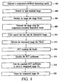
- a compression-considered demosaicing matrix is generated according to the DCT band-limited interpolation method or the DCT Bayesian approach method.
- an input mosaiced image is received.
- the input mosaiced image is partitioned into image blocks.
- the input image may be partitioned into 16 ⁇ 16 pixel image blocks.
- the input image is demosaiced using the compression-considered demosaicing matrix.
- the demosaiced image is color and tone enhanced. Step 810 is an optional step, and thus, may be omitted from the method.
- the demosaiced image is partitioned into blocks for compression.
- the blocks are then DCT transformed, at step 814.
- DCT coefficients of the image are derived.
- the DCT coefficients are quantized.
- the quantized coefficients are then coded using, for example, Huffman tables or arithmetic coding, to derive a compressed image file, at step 818.
- the compressed image file is outputted.
- steps 810, 812 and 814 are omitted from the method.
- the DCT coefficients are generated by the demosaicing operation at step 808.
- steps 808 and 812 are combined into a single step of demosaicing the input mosaiced image using the compression-considered demosaicing matrix to derive the DCT coefficients.
- demosaicing methods and the corresponding demosaicing matrices can be modified to be applicable to wavelet-based compression schemes, such as the JPEG 2000.
- the transformation matrix as defined in equation (5)
- the formulation and solution of the reconstruction problem will be the same.
- the resulting demosaicing matrix can then be used to demosaic input mosaiced images, prior to being compressed using the wavelet-based compression scheme. Consequently, the only significant modification needed to convert the image processing systems 100 and 700 to an image processing system that utilizes a wavelet-based compression scheme is the replacement of either the compression module 112 or the compression module 706 with a comparable compression module that performs compression based on wavelets.
Description
- The invention relates generally to the field of image processing, and more particularly to a system and method for demosaicing raw data (mosaiced) images.
- Color digital cameras are becoming ubiquitous in the consumer marketplace, partly due to progressive price reductions. Color digital cameras typically employ a single optical sensor, either a Charge Coupled Device (CCD) sensor or a Complementary Metal Oxide Semiconductor (CMOS) sensor, to digitally capture a scene of interest. Both CCD and CMOS sensors are only sensitive to illumination. Consequently, these sensors cannot discriminate between different colors. In order to achieve color discrimination, a color filtering technique is applied to separate light in terms of base colors, typically red, green and blue.
- A common filtering technique utilizes a color-filter array (CFA), which is overlaid on a sensor array, to separate colors of impinging light in a Bayer pattern. The Bayer pattern is a periodic pattern with a period of two different color pixels in each dimension (vertical and horizontal). In the horizontal direction, a single period includes either a green pixel and a red pixel, or a blue pixel and a green pixel. In the vertical direction, a single period includes either a green pixel and a blue pixel, or a red pixel and a green pixel. Therefore, the number of green pixels is twice the number of red or blue pixels. The reason for the disparity in the number of green pixels is because the human eye is not equally sensitive to all three primary colors. Consequently, more green pixels are needed to create a color image of a scene that will be perceived as a "true color" image.
- Due to the CFA, the image captured by the sensor is therefore a mosaiced image, also called "raw data" image, where each pixel only holds the value for either red, green or blue. The raw data image can then be demosaiced to create a color image by estimating the actual color value, the combination of red, green and blue, for each pixel of the image. The color value of a pixel is estimated by using color information from surrounding pixels.
- There are a number of conventional demosaicing methods to convert a raw data image into a color image. Three main common categories of demosaicing methods include interpolation-based methods, feature-based methods, and Bayesian methods. The interpolation-based demosaicing methods use simple interpolation formulas to interpolate the color planes separately. The interpolation-based demosaicing methods include bi-linear methods, band-limited interpolation methods using sinc() functions, spline interpolation methods, and the like. The feature-based demosaicing methods examine local features of a given image at the pixel level, and then interpolate the image accordingly. The basic idea of the feature-based methods is to avoid interpolating across edges of features. The Bayesian methods attempt to find the most probable color image, given the data, by assuming some prior knowledge of the image structure.
- After the raw data image has been demosaiced, the image is usually processed through a color-conversion operation and tone mapping, which are part of the image pipe-line. The resulting image is then typically stored in the camera using some sort of image compression, such as JPEG or JPEG-like compression schemes, to reduce the size of the image file. Therefore, the digital image that is eventually downloaded from the digital camera by the user is usually a compressed image file.
- US 5,838,818 discloses a demosaicing method in which the mosaiced digital image is processed using a compressing scheme, wherein a raw digital color image is acquired, and the raw image undergoes space transformation and interpolation before being compressed to yield the compressed image. It is described that, before performing the compression algorithm, it is first necessary to transform the image to a luminance/chrominance space. To carry out this transformation, it is first necessary to demosaic the image. Accordingly, demosaicing, color space transformation and compression are performed separately in subsequent steps. Similar prior art is described in WO 01/26359.
- US 5,065,229 describes a method for image compression, in which image data are processed by the sequential steps of interpolation, separating the image into three color planes, and image compression. This document does not make reference to a demosaicing process.
- Since in the prior art the compression process is performed subsequent to the demosaicing process, some image enhancements achieved as a result of the demosaicing process may be significantly reduced or completely off-set by the compression process. As an example, the demosaicing process may create/predict high frequency components in the signal to produce a sharper image. However, the compression process may eliminate or reduce high frequency components of the input image due to the use of quantizers. Therefore, any advantage gained in the demosaicing process may be negated by the compression process.
- In view of the above concern, there is a need for a system and method for efficiently processing digitally captured images such that the demosaicing process complements the subsequent compression process.
- The present invention provides a method of demosaicing a mosaiced image according to
claim 1 and a system for processing a mosaiced image according to claim 5. - A system and method for processing mosaiced images utilizes a compression-aware demosaicing process that takes into consideration a subsequent compression process. The compression-aware demosaicing process is performed using a compression-considered demosaicing operator that incorporates a color space conversion operator and a frequency-based transformation operator, which are typically associated with the compression process. Consequently, the overall efficiency of the system and method is significantly increased. Furthermore, the compression-aware demosaicing process produces artifacts that complement the artifacts produced by the subsequent compression process such that the artifacts are less visible in the final color images, which increases the quality of the final color images.
- A method of processing a mosaiced image in accordance with the present invention includes steps of receiving the mosaiced image, which is a representation of a scene of interest, and processing the mosaiced image using a demosaicing operator on blocks of the mosaiced image to derive a representation of a demosaiced image. The demosaicing operator incorporates a frequency-based transformation operator to take into account a subsequent frequency-based compression process. The demosaicing operator may also incorporate a color space conversion operator. The color space conversion operator may be an operator for converting from the RGB color space to the luminance, red chrominance and blue chrominance (Yc r c b ) color space. The method may also include a step of compressing the representation of the demosaiced image using a frequency-based compression scheme, such as a DCT-based compression scheme or a wavelet-based compression scheme.
- The frequency-based transformation operator incorporated in the demosaicing operator may be a DCT-based transformation operator. In another embodiment, the frequency-based transformation operator is a wavelet-based transformation operator. The frequency-based transformation operator, as well as the demosaicing operator, may be matrices.
- In one embodiment, the step of processing the mosaiced image is a step of interpolating the mosaiced image using the demosaicing operator, which is derived by defining selected coefficients of transformation-related coefficients as being equal to zero. The selected coefficients may be higher frequency components than remaining coefficients of the transformation-related coefficients. In another embodiment, the step of processing the mosaiced image is a step of interpolating the mosaiced image using the demosaicing operator, which is derived by defining the transformation-related coefficients as having a predefined probability distribution. The predefined probability distribution may be a Normal distribution. In this embodiment, the demosaicing operator may be derived using the Bayesian rule.
- The representation of the demosaiced image derived from the step of processing the mosaiced image may include a number of image pixel values of the demosaiced image. In another embodiment, the representation of the demosaiced image includes a number of transformed coefficients of the demosaiced image.
- A system for processing a mosaiced image in accordance with the present invention includes a compression-aware demosaicing module and a compression module. The compression-aware demosaicing module is configured to demosaic the mosaiced image to produce a representation of a demosaiced image using a demosaicing operator that incorporates a frequency-based transformation operator. The compression module is configured to compress the representation of the demosaiced image to produce a compressed image file by performing a frequency-based compression process. In an embodiment, the compression-aware demosaicing module and the compression module are embodied in an application specific integrated circuit.
- In one embodiment, the demosaicing operator incorporates a color space conversion operator for converting to the Yc b c r color space. In another embodiment, the frequency-based transformation operator incorporated in the demosaicing operator is a DCT-based transformation operator, and the frequency-based compression process performed by the compression means is a DCT-based compression process. In another embodiment, the frequency-based transformation operator is a wavelet-based transformation operator, and the frequency-based compression process is a wavelet-based compression process. The frequency-based transformation operator, as well as the demosaicing operator, may be matrices.
- The demosaicing operator may be derived by defining transformation-related coefficients that are associated with the frequency-based compression process performed by the compression module. In one embodiment, the demosaicing operator is derived by defining selected coefficients of the transformation-related coefficients as being equal to zero. In another embodiment, the demosaicing operator is derived by defining the transformation-related coefficients as having a predefined probability distribution, which may be a Normal distribution. In this embodiment, the demosaicing operator may be derived using the Bayesian rule.
- The representation of the demosaiced image produced by the demosaicing means may include a number of image pixel values of the demosaiced image. In another embodiment, the representation of the demosaiced image includes a number of transformed coefficients of the demosaiced image.
- Other aspects and advantages of the present invention will become apparent from the following detailed description, taken in conjunction with the accompanying drawings, illustrated by way of example of the principles of the invention.
-
- Fig. 1 is a block diagram of an image processing system that performs compression-aware demosaicing process in accordance with the present invention.
- Fig. 2 is a block diagram of a compression-aware demosaic module included in the image processing system of Fig. 1.
- Fig. 3 is a block diagram of a compression module included in the image processing system of Fig. 1.
- Fig. 4 illustrates various norms that can be used to generate the compression-considered demosaicing matrix for a DCT band-limited interpolation method in accordance with a first embodiment of the invention.
- Fig. 5 is a block diagram of a matrix generating system that can be used to generate the compression-considered demosaicing matrix in accordance with the first embodiment of the invention.
- Fig. 6 is a block diagram of a matrix generating system that can be used to generate the compression-considered demosaicing matrix in accordance with a second embodiment of the invention.
- Fig. 7 is a block diagram of an image processing system in accordance with an alternative embodiment of the invention.
- Fig. 8 is a process flow diagram of a method of processing a mosaiced image in accordance with the present invention.
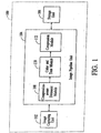
- With reference to Fig. 1, an
image processing system 100 in accordance with the present invention is shown. The image processing system operates to digitally capture a scene of interest as a mosaiced or raw data image. The mosaiced image is then demosaiced and subsequently compressed for storage by the system. The image processing system utilizes a compression-aware demosaicing procedure that takes into consideration the fact that the demosaiced image is subsequently compressed. As a result, the compression-aware demosaicing procedure produces artifacts that complement the artifacts produced by the subsequent compression procedure. Thus, the overall visual distortion caused by the combined artifacts is significantly reduced, which increases the quality of the final digital image. In addition, the compression-aware demosaicing procedure performs steps that are typically performed during a compression process, which increases the efficiency of the image processing system to process the captured image. - The
image processing system 100 includes animage capturing unit 102, animage pipeline unit 104, and astorage unit 106. The image capturing unit includes a sensor and a color-filter array (CFA). The sensor may be a Charge Coupled Device (CCD) sensor, a Complementary Metal Oxide Semiconductor (CMOS) sensor, or other type of photo-sensitive sensor. In an exemplary embodiment, the CFA includes red, blue and green filters arranged in a Bayer filter pattern. However, the CFA may include filters of other colors arranged in a different filter pattern. The image capturing unit operates to digitally capture a scene of interest as a mosaiced or raw data image having a color pattern in accordance with the filter pattern of the CFA, e.g., the Bayer pattern. - The
image pipeline unit 104 of theimage processing system 100 includes a compression-aware demosaic module 108, a color andtone module 110, and acompression module 112. These modules of the image pipeline unit represent functional blocks and are not necessarily separate components. Preferably, the image pipeline unit is an application specific integrated circuit (ASIC). - The compression-
aware demosaic module 102 of theimage pipeline unit 104 operates to demosaic a raw data image into a demosaiced or color image. The demosaicing process is performed such that the subsequent compression process performed by thecompression module 112 is taken into consideration. The components of the compression-aware demosaicing module are shown in Fig. 2. The compression-aware demosaicing module includes animage partitioning unit 202, aninterpolation unit 204, and a compression-considereddemosaicing matrix 206. The image partitioning unit operates to partition an input mosaiced image into image blocks, which are equivalent to the blocks that will be operated on by the compression module. As an example, the image partitioning unit may partition the input mosaiced image into 16×16 pixel image blocks. The interpolation unit operates to demosaic each image block of the mosaiced image by multiplying the image block with the compression-considereddemosaicing matrix 206 to produce a demosaiced image. Thus, the compression-considereddemosaicing matrix 206 is a demosaicing operator that interpolates a mosaiced image into a demosaiced image. - In a first embodiment, the compression-considered
demosaicing matrix 206 is derived using a Discrete Cosine Transform (DCT) band-limited approach. Thus, in this embodiment, the interpolation unit can be said to perform a demosaicing process using a DCT band-limited interpolation method. In a second embodiment, the compression-considered demosaicing matrix is derived using a DCT Bayesian approach. In this embodiment, the interpolation unit can be said to perform a demosaicing process using a DCT Bayesian method. As described in detail below, the compression-considered demosaicing matrix incorporates a DCT transformation operator, a sampling operator and a color conversion matrix. The operations associated with these operators are conventionally performed as part of the compression process. Since the compression-considered demosaicing matrix incorporates such operators, some or all of the operations associated with these operators need not be performed during the subsequent compression process. - The compression-considered
demosaicing matrix 206 may be stored in a read-only memory (not shown) associated with theimage pipeline unit 104. Alternatively, the compression-considered demosaicing matrix may be stored in thestorage unit 106. - The color and
tone module 110 of the image pipeline unit operates to perform color and tone enhancements to a demosaiced image from the compression-aware demosaic module 108. These enhancements are conventional operations and thus, are not described herein. The color and tone module may perform other conventional image operations such as flare-correction and intermediate color conversion. The color and tone module is optional and may be deleted from theimage pipeline unit 104. - The
compression module 112 of theimage pipeline unit 104 operates to compress the demosaiced image to a compressed image file using a DCT-based compression scheme, such as the JPEG compression scheme. The compression module is described herein as using the JPEG compression scheme. For reference, a conventional JPEG compression scheme is briefly described. - For an input RGB image (e.g., a demosaiced image), each pixel of the RGB image is transformed into the luminance, red chrominance and blue chrominance (Yc r c b ) color space. The space components of the Yc b c r color space are then sampled, for example, at 4:1:1. The Y space component is not altered. However, the c b and c r space components are sampled by a factor of two in each axis. Thus, the number of c b and c r samples is reduced by a factor of four. This is in line with the human visual perception which is less sensitive to sharp variations in color information.
- Next, each of the Yc b c r color planes is partitioned into disjoint blocks of 8x8. Each of these blocks is then processed in the following manner. The 8×8 block of scalars is transformed using the DCT into a set of 64 coefficients, which can be arranged as an 8x8 array. The set of 64 DCT coefficients is then quantized using a uniform quantizer, which utilizes different quantization step sizes. In general, the higher frequency coefficients are quantized using larger quantization step size. Quantization is a non-linear, non-invertible operation. The quantized coefficients are then coded using a known coding technique, such as Huffman tables or arithmetic coding. Lastly, the coded data is wrapped in a standard file format.
- An important feature of the JPEG compression procedure is that the compression scheme assumes that the DCT coefficients that are quantized to a value of greater than zero are concentrated in the low frequencies. Another important feature is that the Y component space has twice the bandwidth of the c b and c r component spaces. Furthermore, all the operations of the procedure are performed on blocks of the image. The operations are performed on 16×16 blocks of the original image, and 8×8 blocks in the transformed/sub-sampled domain. Note that the partitioning of the image into blocks can be done before the color-conversion and sub-sampling, as these steps are point-wise operations that do not interact across block boundaries.
- Turning to Fig. 3, the
compression module 112 of theimage pipeline unit 104 includes animage partitioning unit 302, aDCT transformation unit 304, aquantization unit 306, and acoefficient coding unit 308. The image partitioning unit performs the image partitioning operation of the JPEG compression scheme. As an example, the image is partitioned into 8x8 blocks of scalars. The DCT transformation unit performs the DCT transformation of the compression scheme. The quantization unit performs the quantization operation of the compression scheme. Lastly, the coefficient coding unit performs the coding operation of the compression scheme. Thus, the compression module does not perform the color conversion and sub-sampling operations of the JPEG compression scheme, which have been included in the demosaicing process performed by the compression-aware demosaic module 108. - The compressed image file produced by the
compression module 112 is then stored in thestorage unit 106 of theimage processing system 100. The storage unit may be a conventional storage memory, such as DRAM or flash memory. Alternatively, the storage unit may be a drive that interfaces with a removable storage medium, such as a standard computer floppy disk. - The
image capturing unit 102, theimage pipeline unit 104, and thestorage unit 106 of thesystem 100 may be included in a single device, such as a digital camera. Alternatively, the image capturing unit may be included in a separate device. In this alternative embodiment, the functions of theimage pipeline unit 104 and thestorage unit 106 may be performed by a computer. - The derivation of the compression-considered
demosaicing matrix 206 is now described. In accordance with the first embodiment, the compression-aware demosaic module 108 of theimage pipeline unit 104 performs a DCT band-limited interpolation using the compression-considered demosaicing matrix to demosaic raw data images. For this embodiment, the compression-considered demosaicing matrix is derived by taking into consideration the band-limiting effect of the subsequent DCT-based compression process performed by thecompression module 112. - The DCT band-limited interpolation method essentially solves the problem of how to effectively interpolate a signal from its samples, when the signal is known to be band-limited in the DCT domain. The problem and its solution are described herein mathematically. To make the explanation more lucid, the description deals with one-dimensional signals. Extensions to the two-dimensional case with three color components will be described further below.
- Let


This signal is sampled by taking every other element to get

which can be written as
where [S] is an

Note that an extension to non-uniform sampling is straight forward. - Let the N×N DCT transformation matrix [T], where each row is a basis function, be defined as:

The transformation matrix [T] is a frequency-based transformation operator. Note that [T] is unitary and real. Namely,
where [I] is the identity matrix and the superscript "t" denotes the transpose of a matrix. Thus, the forward and backward DCT of the vector x̅can be written as

Note that x̅ c , the DCT coefficients vector, is the same length (N) as the original signal. - Let a signal q̅ be defined to be band-limited and denoted as

Using this notation, x̅ will now be defined to be DCT band-limited, and denoted as
- The band-limitedness of the DCT coefficients is assumed on the DCT of the image when in Yc b c r color space. Thus, a 3x3 transformation matrix from RGB values to Yc b c r values is needed. Assuming the RGB space is well defined, the transformation matrix can be readily defined. In general, the transformation matrix will depend on the RGB domain of the image. Where RGB values are assumed to be in the range [0,1], a sample transformation is:

The offset of the transformation is ignored, and the color transformation matrix from RGB to Yc b c r will be denoted as [C r2y ]. The inverse transformation will be denoted as [C y2r ]. These color transformation matrices are color space conversion operators that can transform signals between an RGB color space and a Yc b c r color space. - The reconstruction problem to be solved can now be defined as follows:

Note that since the original signal, x̅, is a discrete signal, the problem is much simpler than in the continuous case. However, this formulation is not yet simple enough, since the problem deals with a constrained solution. Namely, the desired formulation is one that has a solution of a linear set of equations, where the solution is constrained to a subspace. - The problem defined in expression (12) can be written in the following equivalence:


The compression-considereddemosaicing matrix 206 is thus given by:
- The unconstrained problem (14) has substituted the problem of finding x̅ ∈ D k
o with the problem of finding a set of coefficients. Depending on the values of k 0 relative to the number of samples, which is N/2 in the current example, the above problem is either under-determined (k 0 >N/2), over-determined (k 0 <N/2), or has the same number of unknowns and equations (k 0 =N/2). According to this classification, the problem can be solved using minimum-norm solution, least-squares solution, or exact inversion. - For two-dimensional signals, there are a number of implementation issues. First, in order to enable a simpler linear-algebra formulation, the column-ordering of the image can be considered. The column order of a matrix can be obtained by concatenating the columns of the matrix to form a vector. Thus, each color-plane can be ordered as one column vector. Second, since the DCT is a separable transform, the DCT can be applied first to rows and then to columns, or vice versa. Moreover, using the Kronecker product, the transformation matrix on a column-order version of the matrix can easily be defined. The last implementation issue involves the frequency of the input signal. A one-dimensional signal has only one-linear axis of frequency and the frequency is a scalar. Thus, the issue of frequency for a one-dimensional signal is straightforward. However, for two-dimensional signals, the issue of frequency is more complex, which is now described.
- Assuming a matrix [A] represents the DCT coefficients of a two-dimensional signal (e.g., one of the image color planes), the band-limitedness to k 0 can be any of the following:


grid 402, where each cell corresponds to one coefficient. The non-shaded cells correspond to the DCT coefficients that have been assumed to be zero. The remaining DCT coefficients are shown as shaded cells. As illustrated by Fig. 4, the band-limitedness depends on the norm used. The cells that are intersected by the boundary between the shaded region and the non-shaded region should be decided as either shaded or non-shaded cells. Alternatively, these intersected cells can be decided using strict inequality for the range. For the Y component, the L 1 norm is found to be more appropriate, due the manner in which the Y component is sampled and the fact that the G component of RGB color space corresponds best to the Y component of Yc r c b color space. - The compression-considered
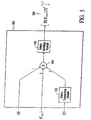
demosaicing matrix 206 is generated by a separate system and then programmed into theimage processing system 100. In Fig. 5, amatrix generating system 500 in accordance with the first embodiment is shown. The matrix generation system is configured to generate the compression-considered demosaicing matrix, as defined by expression (15). The system of Fig. 5 includes amatrix transposing module 502, amultiplication module 504 and amatrix inverting modules 506. Although the modules 502-506 may be implemented in any combination of hardware, firmware and software, these modules are preferably embodied in the matrix generating system as a software program that performs the functions of the modules 502-506 when executed by a processor (not shown). - In operation, the
matrix transposing module 502 of thematrix generation system 500 receives an input matrix [T], which is the DCT transformation matrix. The matrix transposing module then transposes the received matrix [T] to output a matrix [T] t , which is transmitted to themultiplication module 504. Themultiplication module 504 receives input matrices [S] and the [C r2y ] and the output matrix [T] t from thematrix transposing module 502. The input matrix [S] is the sampling matrix. The input matrix [C r2y ] is the color transformation matrix. The multiplication module then multiplies the three received matrices in the order illustrated in Fig. 5 to derive a matrix [S][C y2r ][T], which is transmitted to thematrix inverting module 506. Themodule 506 then inverts the matrix [S][C y2r ][T] to generate the compression-considereddemosaicing matrix 206, as defined by expression (15). - In accordance with the second embodiment, the compression-
aware demosaic module 108 of theimage pipeline unit 104 performs a DCT Bayesian demosaicing process using the compression-considereddemosaicing matrix 206 to demosaic raw data images. For this embodiment, the compression-considered demosaicing matrix is derived by assuming some a priori knowledge about the probability distribution of the DCT coefficients. - The DCT Bayesian approach method associates a probability distribution function with each DCT coefficient. Furthermore, the DCT Bayesian approach method assumes that the coefficients are jointly Normal, with mean vector µ̅c and covariance matrix [R c ], or expressed mathematically:


The following notations for general Normal distributions are used herein:


- The DCT Bayesian approach uses an additive noise model to formulate the reconstruction problem. The additive noise model is expressed as:

where n̅ has a Normal distribution with covariance matrix [R n ],
The above additive noise model is appropriate since it is natural to assume the measurements are noisy. - Using the above assumptions, the problem of reconstruction can now be formulated as follows:

The problem (26) is solved using the Bayesian Rule (19). Since the sampled data y̅ is assumed to be given, x̅ is chosen such that:

Using expressions (23) and (25), equation (28) can be written as:
where c is a constant, independent of x̅. The ½ factor is dropped, since this factor is eventually cancelled. With respect to the coefficients, the assumption is that the coefficients in the transformed domain have a known Normal distribution. In addition, a linear transformation of a Normal vector is Normal. Thus, the probability of the original discrete signal x̅ can be written as:


The above probability can then be written in the following log form:


where

Below are two derivative rules for vectors:


Equating to zero and solving for x̅


demosaicing matrix 206 is thus given by:
The term [Q]-1[R x ]-1µ̅ x of equation (46) represents bias. Assuming known noise and known distribution of the coefficients, equation (46) gives a closed form solution to find the most probable x̅, given the measurements y̅. - The level of noise can be assumed as needed. If the noise is assumed to be very low, the resulting image at the sampling points is essentially forced to be exactly equal to the sample values. However, if the noise is assumed to be high, the values at the sampling points are regarded merely as recommended values to the algorithm. Note that noise can be estimated for the specific type and arrangement of components included in the system. The distribution of the coefficients may be estimated using DCT models or by computing statistics from a number of sample images.
- The bias term [Q]-1[R x ]-1µ̅ x in equation (48) can be determined off-line. In practice, this bias term can be added after image blocks have been multiplied by the compression-considered
demosaicing matrix 206 by theinterpolation unit 204 of the compression-aware demosaic module 108. - In Fig. 6, a
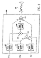
matrix generating system 600 in accordance with the second embodiment is shown. The matrix generation system is configured to generate the compression-considereddemosaicing matrix 206, as defined by expression (48). The system of Fig. 6 includesmatrix inverting modules matrix transposing module 608,multiplication modules module 614. Although the modules 602-614 may be implemented in any combination of hardware, firmware and software, these modules are preferably embodied in the matrix generating system as a software program that performs the functions of the modules 602-614 when executed by a processor (not shown). - In operation, the
matrix inverting module 602 of thematrix generation system 600 receives an input matrix [R x ]. The input matrix [R x ] is the covariance matrix of x (original discrete signals), which can be estimated by using various conventional methods, such as by using DCT models or by computing statistics from a number of sample images. Themodule 602 then inverts the received matrix [R x ] to output a matrix [R x ]-1, which is transmitted to the summingmodule 614. Thematrix inverting module 604 receives an input matrix [R n ]. The input matrix [R n ] is the covariance matrix of n (noise), which can be estimated for the specific type and arrangement of components included in theimage processing system 100 of Fig. 1. Themodule 604 then inverts the received matrix [R n ] to output a matrix [R n ]-1, which is transmitted to themultiplication modules matrix transposing module 608 receives an input matrix [S]. The matrix transposing module then transposes the received matrix [S] to output a matrix [S] t , which is also transmitted to the multiplication modules 510 and 512. - The
multiplication module 610 receives the two output matrices [S] t and [R n ]-1 from thematrix transposing module 608 and thematrix inverting module 604, respectively, and the input sampling matrix [S]. Themultiplication module 610 then multiplies the three received matrices in the order illustrated in Fig. 6 to derive a matrix [S] t [R n ]-1[S], which is transmitted to the summingmodule 614. The summing module receives the matrix [S] t [R n ]-1[S] from themultiplication module 610 and the matrix [R x ]-1 from thematrix inverting module 602. The summing module then adds the two received matrices to output a matrix [R x ]-1+[S] t [R n ]-1[S], which is transmitted to thematrix inverting module 606. The matrix [R x ]-1+[S] t [R n ][S] is equivalent to the matrix [Q], as defined in expression (41). Therefore, the matrix [R x ]-1+[S] t [R n ][S] will now be referred as the matrix [Q]. Themodule 606 inverts the received matrix [Q] and output a matrix [Q]-1, which is transmitted to themultiplication module 612. Themodule 612 receives the matrix [Q]-1 from thematrix inverting module 606, the matrix [S] t from thematrix transposing module 608, and the matrix [R n ]-1 from thematrix inverting module 604. Themultiplication module 612 then multiplies the three received matrices in the order illustrated in Fig. 6 to generate the compression-considereddemosaicing matrix 206, as defined by expression (48). - With reference to Fig. 7, an
image processing system 700 in accordance with an alternative embodiment is shown. Theimage processing system 700 includes a number of components found in theimage processing system 100, which are shown in Figs. 1, 2 and 3. These common components are indicated in Fig. 7 by the same reference numerals. Theimage processing system 700 of Fig. 7 includes theimage capturing unit 102, animage pipeline unit 702 and thestorage unit 106. Theimage pipeline unit 702 includes a compression-aware demosaic module 704 and acompression module 706. Similar to the compression-aware demosaic module 108 of thesystem 100 of Fig. 1, the compression-aware demosaic module 704 includes theimage partitioning unit 202 and theinterpolation unit 204. However, the compression-aware demosaic module 704 utilizes a different compression-considereddemosaicing matrix 708. Using the compression-considereddemosaicing matrix 708, the compression-aware demosaic module 706 outputs a set of DCT coefficients for each image block processed by theinterpolation unit 204. In effect, theinterpolation unit 204 performs DCT transformation, as well as demosaicing. Thus, thecompression module 706 needs only to perform quantization and coding to complete the compression process. Consequently, the compression module includes only thequantization unit 306 and thecoefficient coding unit 308. - The compression-
aware demosaic module 704 can perform either the DCT band-limited interpolation method or the DCT Bayesian approach method, depending on the compression-considereddemosaicing matrix 708. For the DCT band-limited interpolation method, the compression-considereddemosaicing matrix 708 is derived by multiplying the compression-considereddemosaicing matrix 206, as defined-in expression (15), with the DCT transformation matrix [T]. The compression-considereddemosaicing matrix 708 is thus given by:
- For the DCT Bayesian approach method, the compression-considered
demosaicing matrix 708 is derived by multiplying the compression-considereddemosaicing matrix 206, as defined in expression (48), with the DCT transformation matrix [T]. The compression-considereddemosaicing matrix 708 is thus given-by:
- The compression-considered
demosaicing matrix 708 in accordance with the DCT band-limited interpolation method, as defined by expression (49), can be generated by a modified version of thematrix generation system 500 of Fig. 5. The modified matrix generation system includes a second multiplication module (not shown) connected to the output of thematrix inverting module 506. Thus, the second multiplication module receives the output from thematrix inverting module 506. In addition, the second multiplication module receives an input matrix [T], which is multiplied to the output of thematrix inverting module 506. The output of the second multiplication module is the compression-considereddemosaicing matrix 708, as defined by expression (49). - The compression-considered
demosaicing matrix 708 in accordance with the DCT Bayesian approach method, as defined by expression (50), can be generated by a modified version of thematrix generation system 600 of Fig. 6. The modified matrix generation system is configured to receive an input matrix [T] at themultiplication module 612, in addition to the outputs from thematrix inverting modules matrix transposing module 608. Themultiplication module 612 thus multiplies the matrices [T], [Q]-1, [R n ]-1, and [S] t to generate the compression-considereddemosaicing matrix 708, as defined by expression (50). - A method of processing a mosaiced image in accordance with the present invention is described with reference to Fig. 8. At
step 802, a compression-considered demosaicing matrix is generated according to the DCT band-limited interpolation method or the DCT Bayesian approach method. Atstep 804, an input mosaiced image is received. Next, atstep 806, the input mosaiced image is partitioned into image blocks. As an example, the input image may be partitioned into 16×16 pixel image blocks. Atstep 808, the input image is demosaiced using the compression-considered demosaicing matrix. Next, at step 810, the demosaiced image is color and tone enhanced. Step 810 is an optional step, and thus, may be omitted from the method. - At step 812, the demosaiced image is partitioned into blocks for compression. The blocks are then DCT transformed, at
step 814. As a result, DCT coefficients of the image are derived. Next, atstep 816, the DCT coefficients are quantized. The quantized coefficients are then coded using, for example, Huffman tables or arithmetic coding, to derive a compressed image file, atstep 818. Next, at step 820, the compressed image file is outputted. - In an alternative embodiment, steps 810, 812 and 814 are omitted from the method. In this embodiment, the DCT coefficients are generated by the demosaicing operation at
step 808. Thus, in this alternative embodiment, steps 808 and 812 are combined into a single step of demosaicing the input mosaiced image using the compression-considered demosaicing matrix to derive the DCT coefficients. - The above-described demosaicing methods and the corresponding demosaicing matrices can be modified to be applicable to wavelet-based compression schemes, such as the JPEG 2000. For a wavelet-based compression scheme, the transformation matrix, as defined in equation (5), is replaced with a wavelet transformation matrix. The formulation and solution of the reconstruction problem will be the same. The resulting demosaicing matrix can then be used to demosaic input mosaiced images, prior to being compressed using the wavelet-based compression scheme. Consequently, the only significant modification needed to convert the
image processing systems compression module 112 or thecompression module 706 with a comparable compression module that performs compression based on wavelets.
Claims (8)
- A method of demosaicing a mosaiced image comprising:receiving (804) said mosaiced image, said mosaiced image being a representation of a scene of interest; and characterized by:processing (808) said mosaiced image by:partitioning said mosaiced image into image blocks, which are equivalent to the blocks that will be operated on in a subsequent compression process; andusing a compression-considered demosaicing matrix (206) on said blocks of said mosaiced image to derive a representation of a demosaiced image, said compression-considered demosaicing matrix incorporating a frequency-based transformation operator, a sampling operator and a color conversion matrix to take into account a subsequent frequency-based compression process.
- The method of claim 1 wherein said processing (808) of said mosaiced image includes interpolating said mosaiced image using said demosaicing matrix (206; 708), said demosaicing matrix being derived by defining selected coefficients (402) of transformation-related coefficients as being equal to zero.
- The method of claim 2 wherein said selected coefficients (402) are higher frequency components than remaining coefficients of said transformation-related coefficients.
- The method of claim 1, 2 or 3 wherein said processing (808) of said mosaiced image includes interpolating said mosaiced image using said demosaicing operator (206; 708), said demosaicing operator being derived by defining transformation-related coefficients as having a predefined probability distribution.
- A system for processing a mosaiced image comprising:a demosaic module (108; 704) for demosaicing said mosaiced image to produce a representation of a demosaiced image said demosaic module comprising an image partitioning unit (202), an interpolation unit (204), and a compression-considered demosaicing matrix (206), said partitioning unit (202) operating to partition said mosaiced image into image blocks which are equivalent to the blocks that will be operated on by the compression module; the interpolation unit (204) operating to multiply each image block with the compression-considered demosaicing matrix (206), wherein the demosaicing matrix incorporates a frequency-based transformation operator, a sampling operator and a color conversion matrix to take into account a subsequent frequency-based compression process, anda compression module (112; 706) for compressing said representation of said demosaiced image to produce a compressed image file, said compression module configured to perform a frequency-based compression process.
- The system of claim 5 wherein said demosaicing matrix (206; 708) is derived by defining transformation-related coefficients that are associated with said frequency-based compression process performed by said compression module (112; 706).
- The system of claim 6 wherein said demosaicing matrix (206; 708) is derived by defining selected coefficients (402) of said transformation-related coefficients as being equal to zero.
- The system of claim 6 wherein said demosaicing matrix (206; 708) is derived by defining said transformation-related coefficients as having a predefined probability distribution.
Applications Claiming Priority (2)
| Application Number | Priority Date | Filing Date | Title |
|---|---|---|---|
| US09/871,408 US7155066B2 (en) | 2001-05-31 | 2001-05-31 | System and method for demosaicing raw data images with compression considerations |
| US871408 | 2001-05-31 |
Publications (2)
| Publication Number | Publication Date |
|---|---|
| EP1262917A1 EP1262917A1 (en) | 2002-12-04 |
| EP1262917B1 true EP1262917B1 (en) | 2006-05-24 |
Family
ID=25357382
Family Applications (1)
| Application Number | Title | Priority Date | Filing Date |
|---|---|---|---|
| EP01129972A Expired - Lifetime EP1262917B1 (en) | 2001-05-31 | 2001-12-17 | System and method for demosaicing raw data images with compression considerations |
Country Status (4)
| Country | Link |
|---|---|
| US (1) | US7155066B2 (en) |
| EP (1) | EP1262917B1 (en) |
| JP (1) | JP2003111099A (en) |
| DE (1) | DE60119904T2 (en) |
Families Citing this family (19)
| Publication number | Priority date | Publication date | Assignee | Title |
|---|---|---|---|---|
| US7191103B2 (en) * | 2001-08-08 | 2007-03-13 | Hewlett-Packard Development Company, L.P. | Predominant color identification in digital images |
| US20040201726A1 (en) * | 2002-03-19 | 2004-10-14 | Bloom Daniel M. | Digital camera and method for balancing color in a digital image |
| JP2004032493A (en) * | 2002-06-27 | 2004-01-29 | Ricoh Co Ltd | Image processing apparatus and image processing method |
| US7768500B2 (en) * | 2003-06-16 | 2010-08-03 | Humanscale Corporation | Ergonomic pointing device |
| US7953156B2 (en) * | 2003-08-29 | 2011-05-31 | Koninklijke Philips Electronics N.V. | System and method for encoding and decoding enhancement layer data using descriptive model parameters |
| US20050119549A1 (en) * | 2003-12-01 | 2005-06-02 | Anastassios Markas | Embedded metal-programmable image processing array for digital still camera and camrecorder products |
| EP1578108A3 (en) * | 2004-03-19 | 2007-05-30 | Ricoh Company, Ltd. | Apparatus and method for generating scanned data in a standard format |
| US7557799B2 (en) | 2004-06-17 | 2009-07-07 | Avago Technologies Ecbu Ip (Singapore) Pte. Ltd. | System for determining pointer position, movement, and angle |
| US7480417B2 (en) * | 2004-10-19 | 2009-01-20 | Microsoft Corp. | System and method for encoding mosaiced image data employing a reversible color transform |
| US7668366B2 (en) | 2005-08-09 | 2010-02-23 | Seiko Epson Corporation | Mosaic image data processing |
| US8237830B2 (en) | 2007-04-11 | 2012-08-07 | Red.Com, Inc. | Video camera |
| EP2793219A1 (en) | 2007-04-11 | 2014-10-22 | Red.Com, Inc. | Video camera |
| US8363267B2 (en) * | 2007-06-01 | 2013-01-29 | Samsung Electronics Co., Ltd. | Image forming apparatus and color converting method thereof |
| KR20090010803A (en) * | 2007-07-24 | 2009-01-30 | 삼성전자주식회사 | Method and mobile terminal for displaying of image data acquired from camera |
| US8270713B2 (en) * | 2007-10-16 | 2012-09-18 | Aptina Imaging Corporation | Method and apparatus providing hardware-efficient demosaicing of image data |
| US8970718B2 (en) | 2012-07-12 | 2015-03-03 | Gopro, Inc. | Image capture accelerator |
| WO2014127153A1 (en) | 2013-02-14 | 2014-08-21 | Red. Com, Inc. | Video camera |
| CN103279932B (en) * | 2013-06-05 | 2016-12-28 | 北京工业大学 | A kind of two dimension synthesis sparse model and dictionary training method based on this model |
| US11019336B2 (en) | 2017-07-05 | 2021-05-25 | Red.Com, Llc | Video image data processing in electronic devices |
Family Cites Families (11)
| Publication number | Priority date | Publication date | Assignee | Title |
|---|---|---|---|---|
| US5065229A (en) * | 1989-07-24 | 1991-11-12 | Eastman Kodak Company | Compression method and apparatus for single-sensor color imaging systems |
| US5778106A (en) * | 1996-03-14 | 1998-07-07 | Polaroid Corporation | Electronic camera with reduced color artifacts |
| US6044177A (en) * | 1997-06-18 | 2000-03-28 | Hewlett-Packard Company | Artifact reduction decompression method and apparatus for interpolated images |
| US5838818A (en) * | 1997-06-18 | 1998-11-17 | Hewlett-Packard Company | Artifact reduction compression method and apparatus for mosaiced images |
| US6392699B1 (en) * | 1998-03-04 | 2002-05-21 | Intel Corporation | Integrated color interpolation and color space conversion algorithm from 8-bit bayer pattern RGB color space to 12-bit YCrCb color space |
| US6625305B1 (en) * | 1999-08-16 | 2003-09-23 | Hewlett-Packard Development Company, L.P. | Image demosaicing method |
| AU7860300A (en) | 1999-10-05 | 2001-05-10 | Sony Electronics Inc. | Demosaicing using wavelet filtering for digital imaging device |
| US6809765B1 (en) * | 1999-10-05 | 2004-10-26 | Sony Corporation | Demosaicing for digital imaging device using perceptually uniform color space |
| US6731794B2 (en) * | 2001-04-12 | 2004-05-04 | Hewlett-Packard Development Company, L.P. | Method and apparatus for estimating true color values for saturated color values in digitally captured image data |
| US6819801B2 (en) * | 2001-06-19 | 2004-11-16 | Agilent Technologies, Inc. | System and method for processing demosaiced images to reduce color aliasing artifacts |
| US7027654B1 (en) * | 2001-08-16 | 2006-04-11 | On2 Technologies | Video compression system |
-
2001
- 2001-05-31 US US09/871,408 patent/US7155066B2/en not_active Expired - Fee Related
- 2001-12-17 EP EP01129972A patent/EP1262917B1/en not_active Expired - Lifetime
- 2001-12-17 DE DE60119904T patent/DE60119904T2/en not_active Expired - Fee Related
-
2002
- 2002-05-30 JP JP2002156783A patent/JP2003111099A/en active Pending
Also Published As
| Publication number | Publication date |
|---|---|
| JP2003111099A (en) | 2003-04-11 |
| DE60119904D1 (en) | 2006-06-29 |
| EP1262917A1 (en) | 2002-12-04 |
| US20030016877A1 (en) | 2003-01-23 |
| DE60119904T2 (en) | 2007-01-25 |
| US7155066B2 (en) | 2006-12-26 |
Similar Documents
| Publication | Publication Date | Title |
|---|---|---|
| EP1262917B1 (en) | System and method for demosaicing raw data images with compression considerations | |
| US6825876B1 (en) | Digital camera device with methodology for efficient color conversion | |
| US7082218B2 (en) | Color correction of images | |
| Koh et al. | New efficient methods of image compression in digital cameras with color filter array | |
| Gunturk et al. | Demosaicking: color filter array interpolation | |
| US7916940B2 (en) | Processing of mosaic digital images | |
| US7369161B2 (en) | Digital camera device providing improved methodology for rapidly taking successive pictures | |
| US7847833B2 (en) | Digital camera device providing improved methodology for rapidly taking successive pictures | |
| US5901242A (en) | Method and apparatus for decoding spatiochromatically multiplexed color images using predetermined coefficients | |
| Lukac et al. | Color image zooming on the Bayer pattern | |
| US20020101524A1 (en) | Integrated color interpolation and color space conversion algorithm from 8-bit bayer pattern RGB color space to 12-bit YCrCb color space | |
| JP2002269556A (en) | Method for removing noise from digital image based on multiresolution | |
| JP2023025085A (en) | Camera image processing method and camera | |
| JP4328424B2 (en) | Image conversion method | |
| Jaiswal et al. | Exploitation of inter-color correlation for color image demosaicking | |
| Suzuki | Wavelet-based spectral–spatial transforms for CFA-sampled raw camera image compression | |
| US20050025379A1 (en) | Digital imaging systems, articles of manufacture, and digital image processing methods | |
| Lee et al. | Lossless compression of HDR color filter array image for the digital camera pipeline | |
| US7158178B1 (en) | Method of converting a sub-sampled color image | |
| De Lavarène et al. | Practical implementation of LMMSE demosaicing using luminance and chrominance spaces | |
| Boo et al. | Multispectral image restoration with multisensors | |
| Paul et al. | Maximum accurate medical image demosaicing using WRGB based Newton Gregory interpolation method | |
| Gevrekci et al. | POCS-based restoration of Bayer-sampled image sequences | |
| Amba et al. | Demosaicing using dual layer feedforward neural network | |
| Alleysson et al. | Frequency selection demosaicking: A review and a look ahead |
Legal Events
| Date | Code | Title | Description |
|---|---|---|---|
| PUAI | Public reference made under article 153(3) epc to a published international application that has entered the european phase |
Free format text: ORIGINAL CODE: 0009012 |
|
| AK | Designated contracting states |
Kind code of ref document: A1 Designated state(s): AT BE CH CY DE DK ES FI FR GB GR IE IT LI LU MC NL PT SE TR |
|
| AX | Request for extension of the european patent |
Free format text: AL;LT;LV;MK;RO;SI |
|
| 17P | Request for examination filed |
Effective date: 20030508 |
|
| AKX | Designation fees paid |
Designated state(s): DE FR GB |
|
| 17Q | First examination report despatched |
Effective date: 20040914 |
|
| GRAP | Despatch of communication of intention to grant a patent |
Free format text: ORIGINAL CODE: EPIDOSNIGR1 |
|
| GRAS | Grant fee paid |
Free format text: ORIGINAL CODE: EPIDOSNIGR3 |
|
| GRAA | (expected) grant |
Free format text: ORIGINAL CODE: 0009210 |
|
| AK | Designated contracting states |
Kind code of ref document: B1 Designated state(s): DE FR GB |
|
| REG | Reference to a national code |
Ref country code: GB Ref legal event code: FG4D |
|
| REF | Corresponds to: |
Ref document number: 60119904 Country of ref document: DE Date of ref document: 20060629 Kind code of ref document: P |
|
| PGFP | Annual fee paid to national office [announced via postgrant information from national office to epo] |
Ref country code: FR Payment date: 20061220 Year of fee payment: 6 |
|
| ET | Fr: translation filed | ||
| PGFP | Annual fee paid to national office [announced via postgrant information from national office to epo] |
Ref country code: GB Payment date: 20061222 Year of fee payment: 6 |
|
| RAP2 | Party data changed (patent owner data changed or rights of a patent transferred) |
Owner name: AGILENT TECHNOLOGIES, INC. |
|
| PLBE | No opposition filed within time limit |
Free format text: ORIGINAL CODE: 0009261 |
|
| STAA | Information on the status of an ep patent application or granted ep patent |
Free format text: STATUS: NO OPPOSITION FILED WITHIN TIME LIMIT |
|
| 26N | No opposition filed |
Effective date: 20070227 |
|
| PGFP | Annual fee paid to national office [announced via postgrant information from national office to epo] |
Ref country code: DE Payment date: 20080131 Year of fee payment: 7 |
|
| GBPC | Gb: european patent ceased through non-payment of renewal fee |
Effective date: 20071217 |
|
| REG | Reference to a national code |
Ref country code: FR Ref legal event code: ST Effective date: 20081020 |
|
| PG25 | Lapsed in a contracting state [announced via postgrant information from national office to epo] |
Ref country code: GB Free format text: LAPSE BECAUSE OF NON-PAYMENT OF DUE FEES Effective date: 20071217 |
|
| PG25 | Lapsed in a contracting state [announced via postgrant information from national office to epo] |
Ref country code: FR Free format text: LAPSE BECAUSE OF NON-PAYMENT OF DUE FEES Effective date: 20071231 |
|
| PG25 | Lapsed in a contracting state [announced via postgrant information from national office to epo] |
Ref country code: DE Free format text: LAPSE BECAUSE OF NON-PAYMENT OF DUE FEES Effective date: 20090701 |