EP1262819A1 - Lens-fitted photo film unit - Google Patents
Lens-fitted photo film unit Download PDFInfo
- Publication number
- EP1262819A1 EP1262819A1 EP02253717A EP02253717A EP1262819A1 EP 1262819 A1 EP1262819 A1 EP 1262819A1 EP 02253717 A EP02253717 A EP 02253717A EP 02253717 A EP02253717 A EP 02253717A EP 1262819 A1 EP1262819 A1 EP 1262819A1
- Authority
- EP
- European Patent Office
- Prior art keywords
- lens
- photo film
- film unit
- fitted photo
- front cover
- Prior art date
- Legal status (The legal status is an assumption and is not a legal conclusion. Google has not performed a legal analysis and makes no representation as to the accuracy of the status listed.)
- Granted
Links
- 239000007850 fluorescent dye Substances 0.000 claims description 5
- 238000000034 method Methods 0.000 claims description 4
- 229920003023 plastic Polymers 0.000 claims description 2
- 239000004033 plastic Substances 0.000 claims description 2
- 239000011347 resin Substances 0.000 abstract description 9
- 229920005989 resin Polymers 0.000 abstract description 9
- 208000007101 Muscle Cramp Diseases 0.000 description 5
- 238000001746 injection moulding Methods 0.000 description 2
- 238000004064 recycling Methods 0.000 description 2
- 238000004804 winding Methods 0.000 description 2
- 239000003990 capacitor Substances 0.000 description 1
- 230000007547 defect Effects 0.000 description 1
- 230000000694 effects Effects 0.000 description 1
- 239000004744 fabric Substances 0.000 description 1
- 239000011521 glass Substances 0.000 description 1
- 238000012986 modification Methods 0.000 description 1
- 230000004048 modification Effects 0.000 description 1
- 230000003287 optical effect Effects 0.000 description 1
- 230000001012 protector Effects 0.000 description 1
- 238000002310 reflectometry Methods 0.000 description 1
- 230000001360 synchronised effect Effects 0.000 description 1
- 235000019640 taste Nutrition 0.000 description 1
- XLYOFNOQVPJJNP-UHFFFAOYSA-N water Substances O XLYOFNOQVPJJNP-UHFFFAOYSA-N 0.000 description 1
Images


Classifications
-
- G—PHYSICS
- G03—PHOTOGRAPHY; CINEMATOGRAPHY; ANALOGOUS TECHNIQUES USING WAVES OTHER THAN OPTICAL WAVES; ELECTROGRAPHY; HOLOGRAPHY
- G03B—APPARATUS OR ARRANGEMENTS FOR TAKING PHOTOGRAPHS OR FOR PROJECTING OR VIEWING THEM; APPARATUS OR ARRANGEMENTS EMPLOYING ANALOGOUS TECHNIQUES USING WAVES OTHER THAN OPTICAL WAVES; ACCESSORIES THEREFOR
- G03B17/00—Details of cameras or camera bodies; Accessories therefor
- G03B17/02—Bodies
-
- G—PHYSICS
- G03—PHOTOGRAPHY; CINEMATOGRAPHY; ANALOGOUS TECHNIQUES USING WAVES OTHER THAN OPTICAL WAVES; ELECTROGRAPHY; HOLOGRAPHY
- G03B—APPARATUS OR ARRANGEMENTS FOR TAKING PHOTOGRAPHS OR FOR PROJECTING OR VIEWING THEM; APPARATUS OR ARRANGEMENTS EMPLOYING ANALOGOUS TECHNIQUES USING WAVES OTHER THAN OPTICAL WAVES; ACCESSORIES THEREFOR
- G03B19/00—Cameras
Definitions
- the present invention relates to a lens-fitted photo film unit, more particularly to a lens-fitted photo film unit in which a logomark, such as a name or a mark of a maker, becomes brilliantly remarkable.
- lens-fitted photo film unit in which an unexposed filmstrip is preloaded.
- the lens-fitted photo film unit is provided with a simple photographic mechanism and popular while a picture is easily photographed with it and it may be brought in a photo finisher after exposure of all frames.
- the lens-fitted photo film unit has a skeleton type of the front cover formed of a transparent resin, and an exposure unit having a photographic mechanism and a flash device can be seen through the front cover.
- protrusions or retractions are formed on an outer surface of the front cover so as to construct letters or marks symbolizing a producer.
- the skeleton type of the lens-fitted photo film unit has a defect in that the letters and the marks formed by the protrusions or retractions are hardly perceived.
- An object of the present invention is to provide a lens-fitted photo film unit in whose transparent part a logomark is provided so as to be more easily perceived.
- the object and the other objects are achieved by forming reflect portions constructing a symbol on an inner face of a transparent member constructing a part of an outer face.
- the reflect portion is constructed of inclined faces of a V-shaped groove and protrusions.
- cramp processed portion is formed around the reflect portion.
- the V-shaped groove and the projections are formed on an inner surface of the front cover.
- the front cover is made of plastics mixed with fluorescent dyes.
- the light which has entered in the transparent member is reflected on the reflect portions such that the symbol may become more brilliant and remarkable.
- a lens-fitted photo film unit 2 is constructed of a unit 3 and an outer sheet 4.
- the outer sheet 4 is formed of a transparent resin film and wound so as to wrap a central part of the unit 3.
- a front surface of the unit 3 is provided with a taking lens 5, a finder objective window 6, a flashlight projector 7 and a flash charger button 8.
- a shutter release button 9 In an upper surface, there are a shutter release button 9, a film counter window 10 and a flash charging completion indicating lamp 11.
- a finder eye-piece window 12 See, FIG.2
- a film winding wheel 13 appear.
- the unit 3 includes a main body 16, the front cover 17 and a rear cover 18.
- the front cover 17 and the rear cover 18 cover the main body 16.
- a cartridge chamber 20 for containing a housing 19 and a film roll chamber 22 for loading a rolled filmstrip 21.
- an exposure aperture 23 determining an exposure area on the filmstrip 21.
- Each bottom of the cartridge chamber 20 and the film roll chamber 22 has an opening.
- the opening of the cartridge chamber 20 is closed with a bottom lid 18a, and that of the film roll chamber 22 is closed with a bottom lid 18b.
- a film winding wheel 13 is attached to an upper surface of the cartridge chamber 20, a film winding wheel 13 is attached.
- an exposure unit 26 is attached to a front surface of the exposure aperture 23, and a flash unit 27 is attached to an upper side of the film roll chamber 22.
- the exposure unit 26 includes a shutter base 26a to which a taking lens 5, a finder optical system and a shutter mechanism and the like are attached.
- the flash unit 27 has a flash circuit formed on a printed circuit board 28. To the printed circuit board 28 are attached a flashlight projector 7 for emitting a flashlight, a main capacitor 29, a dry battery 30, a battery holder 31, a charging switch 32 and a synchronized switch 33 which all form a part of the flash circuit.
- the main body 16, the rear cover 18 and the exposure unit 26 are formed of a light-shielding resin by injection molding.
- the filmstrip 21 is kept between the main body 16 and the rear cover 18 in a light-tight fashion.
- a light from objects passes through the taking lens 5, and thereafter is shielded by the shutter base 26a and the main body 16.
- the front cover 17 is formed by injection molding of a transparent resin in which a fluorescent dye is mixed, for example, lumogene, hostasol and the like.
- a semitransparent resin may be used such that an inside of the unit 3 may be seen through the front cover 17.
- the front cover 17 is confronted to the main body 16.
- a front surface 17a of the front cover 17 is flat.
- a V-shaped grooves 36 are provided so as to form edges of the logomark 34.
- the front cover 17 contains the fluorescent dye, the reflection of the light increases. Note that the front cover 17 may not contain the fluorescent dye.
- the front cover 17 When the front cover 17 is set in the light, the light passes through a part of the front cover 17 to reach the main body 16. However, as the main body 16 is made of the light-shielding resin, the filmstrip 21 is not exposed in the light. A part of the light in the front cover 17 further extends in the all over the front cover 17. After reflecting on groove walls 36a of the V-shaped groove 36 several times, the part of the light is directed to the outside of the lens-fitted photo film unit 2. Thereby, as the incident angle of the part of the light is small, the part of the light passes through the front cover 17. Further, when the light directly reaches the groove walls 36a, the groove walls 36a reflects the light toward the outside. Thus, the density of the light reflected on the groove walls 36a toward the outside becomes widely larger. Further, the V-shaped grooves 36 are provided in edges of the logomark 34, outlines of the logomark 34 become clearer.
- the lens-fitted photo film unit 2 is provided for a photo finisher.
- the exposed filmstrip 21 is unloaded, the unit body 3 is sent to a recycling fabric for recycling and reusing.
- the third person may be a third person who loads a fresh filmstrip in the empty unit 3 to sold it. Thereby the third person cut a part of the front cover 17 to remove the V-shaped groove 36 constructing the logomark 34.
- the third person must separate the front cover 17 from the unit 3 in order to remove the V-shaped groove 36.
- the arrangement becomes complex.
- a position where the logomark 34 is cut down becomes unnatural and seen from the outside through the transparent front cover 17. Accordingly, the changing of the filmstrip is prevented.
- the logomark 34 may be formed by a protrusion 42 on a rear surface 41a of a front cover 41.
- the protrusion 42 has inclined faces along edges of the logomark 34. As the light is reflected on the inclined faces the outline of the logomark 34 becomes clearer and more remarkably.
- a V-shaped groove a retraction may be formed on a front surface 17a of the front cover 17 in a position corresponding to the logomark 34.
- the light may be reflected on the V-shaped groove and the protrusion on the front surface 17a, and the V-shaped groove and the protrusion forming outlines of the logomark are also perceived.
- the logomark 34 becomes much clearer and more remarkable.
- the side surface of the protrusion 42 and the groove walls 36a of the groove 36 may be perpendicularly formed.
- cramps 55 are formed around grooves 54 on a rear surface 53b of a front cover 53.
- the cramp process portion 55 diffuses the light from the outside.
- a position of the cramp process portion 55 becomes semi-transparent, and therefore the main body 16 is seen with less transparency.
- the main body 16 is seen behind the front cover 53. Therefore, the logomark 34 is more remarkable.
- the cramp process portion 55 may be also formed around the logomark 34 on a front surface 53a of the front cover 53. Further, a glass may be applied on the V-shaped groove 54 and the protrusion 42 so as to increase the reflectivity.
- the logomark 34 may be formed on transparent member which is not restricted in the front cover. As the transparent member there is a protector attached to an emitting surface of the flashlight projector 7, and the shutter release button 9 may be formed of the transparent resin. Further, the present invention may be applied to a water shielding cover for covering the lens-fitted photo film unit 2 in a water-tight fashion or an outer cover for covering the lens-fitted photo film unit 2.
- the logomark 34 is for example letters, marks and numbers.
Landscapes
- Physics & Mathematics (AREA)
- General Physics & Mathematics (AREA)
- Structure And Mechanism Of Cameras (AREA)
- Camera Bodies And Camera Details Or Accessories (AREA)
Abstract
Description
- The present invention relates to a lens-fitted photo film unit, more particularly to a lens-fitted photo film unit in which a logomark, such as a name or a mark of a maker, becomes brilliantly remarkable.
- In a market is sold a lens-fitted photo film unit in which an unexposed filmstrip is preloaded. The lens-fitted photo film unit is provided with a simple photographic mechanism and popular while a picture is easily photographed with it and it may be brought in a photo finisher after exposure of all frames.
- Recently a design of the lens-fitted photo film unit is often improved as to fit to various tastes of users. For example, the lens-fitted photo film unit has a skeleton type of the front cover formed of a transparent resin, and an exposure unit having a photographic mechanism and a flash device can be seen through the front cover.
- In the skeleton type, for example, protrusions or retractions are formed on an outer surface of the front cover so as to construct letters or marks symbolizing a producer. However in the skeleton type of the lens-fitted photo film unit has a defect in that the letters and the marks formed by the protrusions or retractions are hardly perceived.
- An object of the present invention is to provide a lens-fitted photo film unit in whose transparent part a logomark is provided so as to be more easily perceived.
- The object and the other objects are achieved by forming reflect portions constructing a symbol on an inner face of a transparent member constructing a part of an outer face. The reflect portion is constructed of inclined faces of a V-shaped groove and protrusions. Around the reflect portion, cramp processed portion is formed.
- In the preferable embodiment, the V-shaped groove and the projections are formed on an inner surface of the front cover. The front cover is made of plastics mixed with fluorescent dyes.
- In the lens-fitted photo film unit of the present invention, the light which has entered in the transparent member is reflected on the reflect portions such that the symbol may become more brilliant and remarkable.
- The above objects and advantages of the present invention will become easily understood by one of ordinary skill in the art when the following detailed description would be read in connection with the accompanying drawings.
- Figure 1 is a perspective view of a lens-fitted photo film unit of the present invention;
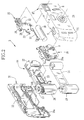
- Figure 2 is an exploded view of the lens-fitted photo film unit in FIG. 1, in which a label is not illustrated;
- Figure 3 is a partial sectional view of the lens-fitted photo film unit in FIG. 1;
- Figure 4 is a same view as FIG. 3, illustrating a situation in which a light is reflected on protrusions formed on a rear face of a front cover;
- Figure 5 is a same view as FIG. 3, in which crimps are formed around grooves.
-
- In FIG. 1, a lens-fitted
photo film unit 2 is constructed of a unit 3 and an outer sheet 4. The outer sheet 4 is formed of a transparent resin film and wound so as to wrap a central part of the unit 3. - A front surface of the unit 3 is provided with a taking
lens 5, a finder objective window 6, a flashlight projector 7 and aflash charger button 8. In an upper surface, there are a shutter release button 9, a film counter window 10 and a flash charging completion indicating lamp 11. In the rear surface, a finder eye-piece window 12 (See, FIG.2) and afilm winding wheel 13 appear. - As shown in FIG. 2, the unit 3 includes a
main body 16, thefront cover 17 and arear cover 18. Thefront cover 17 and therear cover 18 cover themain body 16. In themain body 16 are formed acartridge chamber 20 for containing ahousing 19 and afilm roll chamber 22 for loading a rolledfilmstrip 21. Between thecartridge chamber 20 and thefilm roll chamber 22 there is anexposure aperture 23 determining an exposure area on thefilmstrip 21. Each bottom of thecartridge chamber 20 and thefilm roll chamber 22 has an opening. The opening of thecartridge chamber 20 is closed with abottom lid 18a, and that of thefilm roll chamber 22 is closed with abottom lid 18b. To an upper surface of thecartridge chamber 20, afilm winding wheel 13 is attached. In themain body 16 anexposure unit 26 is attached to a front surface of theexposure aperture 23, and aflash unit 27 is attached to an upper side of thefilm roll chamber 22. Theexposure unit 26 includes ashutter base 26a to which a takinglens 5, a finder optical system and a shutter mechanism and the like are attached. - The
flash unit 27 has a flash circuit formed on a printedcircuit board 28. To the printedcircuit board 28 are attached a flashlight projector 7 for emitting a flashlight, amain capacitor 29, adry battery 30, abattery holder 31, acharging switch 32 and asynchronized switch 33 which all form a part of the flash circuit. - The
main body 16, therear cover 18 and theexposure unit 26 are formed of a light-shielding resin by injection molding. When a rear surface of themain body 16 is covered with therear cover 18, thefilmstrip 21 is kept between themain body 16 and therear cover 18 in a light-tight fashion. A light from objects passes through the takinglens 5, and thereafter is shielded by theshutter base 26a and themain body 16. Further, thefront cover 17 is formed by injection molding of a transparent resin in which a fluorescent dye is mixed, for example, lumogene, hostasol and the like. Instead of the transparent resin, a semitransparent resin may be used such that an inside of the unit 3 may be seen through thefront cover 17. - As shown in FIG. 3, the
front cover 17 is confronted to themain body 16. Afront surface 17a of thefront cover 17 is flat. On arear surface 17b of thefront cover 17, a V-shaped grooves 36 are provided so as to form edges of thelogomark 34. As thefront cover 17 contains the fluorescent dye, the reflection of the light increases. Note that thefront cover 17 may not contain the fluorescent dye. - An effect of the above embodiment will be described now. When the
front cover 17 is set in the light, the light passes through a part of thefront cover 17 to reach themain body 16. However, as themain body 16 is made of the light-shielding resin, thefilmstrip 21 is not exposed in the light. A part of the light in thefront cover 17 further extends in the all over thefront cover 17. After reflecting ongroove walls 36a of the V-shaped groove 36 several times, the part of the light is directed to the outside of the lens-fittedphoto film unit 2. Thereby, as the incident angle of the part of the light is small, the part of the light passes through thefront cover 17. Further, when the light directly reaches thegroove walls 36a, thegroove walls 36a reflects the light toward the outside. Thus, the density of the light reflected on thegroove walls 36a toward the outside becomes widely larger. Further, the V-shaped grooves 36 are provided in edges of thelogomark 34, outlines of thelogomark 34 become clearer. - Further, after exposure of all frames, the lens-fitted
photo film unit 2 is provided for a photo finisher. In the photo finisher, the exposedfilmstrip 21 is unloaded, the unit body 3 is sent to a recycling fabric for recycling and reusing. - Further, there may be a third person who loads a fresh filmstrip in the empty unit 3 to sold it. Thereby the third person cut a part of the
front cover 17 to remove the V-shapedgroove 36 constructing thelogomark 34. However, as formed on arear surface 17b of thefront cover 17 in the present invention, the third person must separate thefront cover 17 from the unit 3 in order to remove the V-shapedgroove 36. Thus, the arrangement becomes complex. Further, a position where thelogomark 34 is cut down becomes unnatural and seen from the outside through the transparentfront cover 17. Accordingly, the changing of the filmstrip is prevented. - As shown in FIG. 4, the
logomark 34 may be formed by aprotrusion 42 on arear surface 41a of afront cover 41. Theprotrusion 42 has inclined faces along edges of thelogomark 34. As the light is reflected on the inclined faces the outline of thelogomark 34 becomes clearer and more remarkably. - Further, a V-shaped groove a retraction may be formed on a
front surface 17a of thefront cover 17 in a position corresponding to thelogomark 34. The light may be reflected on the V-shaped groove and the protrusion on thefront surface 17a, and the V-shaped groove and the protrusion forming outlines of the logomark are also perceived. Thus thelogomark 34 becomes much clearer and more remarkable. Further, the side surface of theprotrusion 42 and thegroove walls 36a of thegroove 36 may be perpendicularly formed. - In FIG. 5,
cramps 55 are formed aroundgrooves 54 on arear surface 53b of afront cover 53. Thecramp process portion 55 diffuses the light from the outside. A position of thecramp process portion 55 becomes semi-transparent, and therefore themain body 16 is seen with less transparency. Further, through another position of thefront cover 17, themain body 16 is seen behind thefront cover 53. Therefore, thelogomark 34 is more remarkable. Furthermore, thecramp process portion 55 may be also formed around thelogomark 34 on a front surface 53a of thefront cover 53. Further, a glass may be applied on the V-shapedgroove 54 and theprotrusion 42 so as to increase the reflectivity. - The
logomark 34 may be formed on transparent member which is not restricted in the front cover. As the transparent member there is a protector attached to an emitting surface of the flashlight projector 7, and the shutter release button 9 may be formed of the transparent resin. Further, the present invention may be applied to a water shielding cover for covering the lens-fittedphoto film unit 2 in a water-tight fashion or an outer cover for covering the lens-fittedphoto film unit 2. Thelogomark 34 is for example letters, marks and numbers. - Various changes and modifications are possible in the present invention and may be understood to be within the present invention.
Claims (8)
- A lens-fitted photo film unit (2) in which an unexposed filmstrip (21) is preloaded, comprising:a transparent member disposed in an outer surface of said lens-fitted photo film unit(2); andreflect portions (36a, 54) provided on an inner surface of said transparent member, said reflect portions (36a) forming outlines of said symbol (34), reflecting an incident light outward of said transparent member for indicating said symbol (34) in brilliancy.
- A lens-fitted photo film unit (2) as described in claim 1, including:an opaque main body (16) for preloading said filmstrip (21);a transparent front cover (17) attached to a front surface of said main body; andan opaque rear cover (18) attached to a rear side of said main body.
- A lens-fitted photo film unit (2) as described in claim 2, wherein said transparent member is said front cover.
- A lens-fitted photo film unit (2) as described in claim 3, wherein said symbol (34) is letters.
- A lens-fitted photo film unit (2) as described in claim 1, wherein said transparent member is made of plastics mixed with fluorescent dyes.
- A lens-fitted photo film unit (2) as described in claim 1, wherein said reflect portions (36a, 54) are grooves formed in V-shape.
- A lens-fitted photo film unit (2) as described in claim 1, wherein an inner surface of said transparent member has protrusions protruding in form of said symbol (34), and inclined faces formed on edges of said protrusions are said reflect portions.
- A lens-fitted photo film unit (3) as described in claim 1, further comprising a crimp process portion (55) formed around said reflect portion (36a, 54).
Applications Claiming Priority (2)
| Application Number | Priority Date | Filing Date | Title |
|---|---|---|---|
| JP2001159024A JP2002351020A (en) | 2001-05-28 | 2001-05-28 | Film unit with lens |
| JP2001159024 | 2001-05-28 |
Publications (2)
| Publication Number | Publication Date |
|---|---|
| EP1262819A1 true EP1262819A1 (en) | 2002-12-04 |
| EP1262819B1 EP1262819B1 (en) | 2005-07-27 |
Family
ID=19002668
Family Applications (1)
| Application Number | Title | Priority Date | Filing Date |
|---|---|---|---|
| EP02253717A Expired - Lifetime EP1262819B1 (en) | 2001-05-28 | 2002-05-27 | Lens-fitted photo film unit |
Country Status (6)
| Country | Link |
|---|---|
| US (1) | US6744979B2 (en) |
| EP (1) | EP1262819B1 (en) |
| JP (1) | JP2002351020A (en) |
| KR (1) | KR100450456B1 (en) |
| DE (1) | DE60205174T2 (en) |
| TW (1) | TW594374B (en) |
Citations (3)
| Publication number | Priority date | Publication date | Assignee | Title |
|---|---|---|---|---|
| WO1996040566A1 (en) * | 1995-06-07 | 1996-12-19 | Rehrig Pacific Company, Inc. | Case with integral sidewall logo |
| US5940637A (en) * | 1997-12-09 | 1999-08-17 | Eastman Kodak Company | Photographic film cartridge containing time and temperature integrating indicator device, and process for controlling photofinishing of film |
| JPH11237676A (en) * | 1998-02-23 | 1999-08-31 | Kanji Nakano | Disposable camera capable of imprinting character, logo and name |
Family Cites Families (5)
| Publication number | Priority date | Publication date | Assignee | Title |
|---|---|---|---|---|
| JPS60247590A (en) * | 1984-05-23 | 1985-12-07 | Dainippon Printing Co Ltd | Formation of picture pattern having fine embossed pattern |
| JPH0954397A (en) * | 1995-08-11 | 1997-02-25 | Fuji Photo Film Co Ltd | Outside case sheet for film unit with lens |
| US6442342B1 (en) * | 1999-01-13 | 2002-08-27 | Eastman Kodak Company | One-time-use camera with electronic flash having film identifying indicia which cannot be removed without destroying flash |
| JP2000330243A (en) * | 1999-03-12 | 2000-11-30 | Fuji Photo Film Co Ltd | Outer package sheet for camera and camera |
| US6330396B1 (en) * | 1999-07-26 | 2001-12-11 | Eastman Kodak Company | Camera having light-blocking label |
-
2001
- 2001-05-28 JP JP2001159024A patent/JP2002351020A/en not_active Ceased
-
2002
- 2002-04-19 KR KR10-2002-0021599A patent/KR100450456B1/en not_active Expired - Fee Related
- 2002-05-08 TW TW091109600A patent/TW594374B/en not_active IP Right Cessation
- 2002-05-27 EP EP02253717A patent/EP1262819B1/en not_active Expired - Lifetime
- 2002-05-27 DE DE60205174T patent/DE60205174T2/en not_active Expired - Fee Related
- 2002-05-28 US US10/155,120 patent/US6744979B2/en not_active Expired - Fee Related
Patent Citations (3)
| Publication number | Priority date | Publication date | Assignee | Title |
|---|---|---|---|---|
| WO1996040566A1 (en) * | 1995-06-07 | 1996-12-19 | Rehrig Pacific Company, Inc. | Case with integral sidewall logo |
| US5940637A (en) * | 1997-12-09 | 1999-08-17 | Eastman Kodak Company | Photographic film cartridge containing time and temperature integrating indicator device, and process for controlling photofinishing of film |
| JPH11237676A (en) * | 1998-02-23 | 1999-08-31 | Kanji Nakano | Disposable camera capable of imprinting character, logo and name |
Non-Patent Citations (1)
| Title |
|---|
| PATENT ABSTRACTS OF JAPAN vol. 1999, no. 13 30 November 1999 (1999-11-30) * |
Also Published As
| Publication number | Publication date |
|---|---|
| US6744979B2 (en) | 2004-06-01 |
| TW594374B (en) | 2004-06-21 |
| JP2002351020A (en) | 2002-12-04 |
| DE60205174D1 (en) | 2005-09-01 |
| KR100450456B1 (en) | 2004-10-01 |
| DE60205174T2 (en) | 2006-03-23 |
| KR20020090855A (en) | 2002-12-05 |
| EP1262819B1 (en) | 2005-07-27 |
| US20020176707A1 (en) | 2002-11-28 |
Similar Documents
| Publication | Publication Date | Title |
|---|---|---|
| GB2196136A (en) | Disposable camera | |
| US5285228A (en) | Photographic film package with anti-reflection substance for viewfinder | |
| US5628039A (en) | Lens-fitted photographic film unit | |
| US5826112A (en) | Lens-fitted photo film unit and classifying apparatus and method for the same | |
| EP1262819B1 (en) | Lens-fitted photo film unit | |
| JPH0545802A (en) | Film unit with lens | |
| JP3558353B2 (en) | Film unit with lens | |
| EP0624819A1 (en) | Single-use camera with indicator lamp visible via light pipe | |
| JPH11231394A (en) | Film unit with lens, film unit with lens provided with built-in stroboscope, housing for storing film unit with lens and housing for film unit with lens | |
| US6014526A (en) | Camera with combination release button for shutter and window for frame counter | |
| GB2335751A (en) | Image composition camera using a camera obscura | |
| JPH06202219A (en) | Camera | |
| JP3882177B2 (en) | camera | |
| US5708858A (en) | Photographic camera | |
| JP3737178B2 (en) | Shading structure of film unit with lens | |
| US5999754A (en) | Compact camera with frame counter made flexible to conserve space | |
| JPH06347864A (en) | Film unit equipped with lens | |
| JPH11183974A (en) | Film unit with lens | |
| JP3233681B2 (en) | Ghost prevention mask for film unit with lens | |
| JPS628030Y2 (en) | ||
| JP2000267168A (en) | Film unit with lens | |
| JP2000066276A (en) | Film unit with lens | |
| JPH086141A (en) | Data imprinting device | |
| JP2002341412A (en) | Lens-fitted photographic film unit | |
| JPH07287284A (en) | Film unit with lens |
Legal Events
| Date | Code | Title | Description |
|---|---|---|---|
| PUAI | Public reference made under article 153(3) epc to a published international application that has entered the european phase |
Free format text: ORIGINAL CODE: 0009012 |
|
| AK | Designated contracting states |
Kind code of ref document: A1 Designated state(s): AT BE CH CY DE DK ES FI FR GB GR IE IT LI LU MC NL PT SE TR |
|
| AX | Request for extension of the european patent |
Free format text: AL;LT;LV;MK;RO;SI |
|
| 17P | Request for examination filed |
Effective date: 20030530 |
|
| AKX | Designation fees paid |
Designated state(s): DE FR GB |
|
| 17Q | First examination report despatched |
Effective date: 20040630 |
|
| GRAP | Despatch of communication of intention to grant a patent |
Free format text: ORIGINAL CODE: EPIDOSNIGR1 |
|
| GRAS | Grant fee paid |
Free format text: ORIGINAL CODE: EPIDOSNIGR3 |
|
| GRAA | (expected) grant |
Free format text: ORIGINAL CODE: 0009210 |
|
| AK | Designated contracting states |
Kind code of ref document: B1 Designated state(s): DE FR GB |
|
| REG | Reference to a national code |
Ref country code: GB Ref legal event code: FG4D |
|
| REF | Corresponds to: |
Ref document number: 60205174 Country of ref document: DE Date of ref document: 20050901 Kind code of ref document: P |
|
| ET | Fr: translation filed | ||
| PLBE | No opposition filed within time limit |
Free format text: ORIGINAL CODE: 0009261 |
|
| STAA | Information on the status of an ep patent application or granted ep patent |
Free format text: STATUS: NO OPPOSITION FILED WITHIN TIME LIMIT |
|
| 26N | No opposition filed |
Effective date: 20060428 |
|
| REG | Reference to a national code |
Ref country code: FR Ref legal event code: TP Ref country code: FR Ref legal event code: CD |
|
| PGFP | Annual fee paid to national office [announced via postgrant information from national office to epo] |
Ref country code: DE Payment date: 20080605 Year of fee payment: 7 |
|
| PGFP | Annual fee paid to national office [announced via postgrant information from national office to epo] |
Ref country code: GB Payment date: 20080528 Year of fee payment: 7 |
|
| GBPC | Gb: european patent ceased through non-payment of renewal fee |
Effective date: 20090527 |
|
| REG | Reference to a national code |
Ref country code: FR Ref legal event code: ST Effective date: 20100129 |
|
| PG25 | Lapsed in a contracting state [announced via postgrant information from national office to epo] |
Ref country code: FR Free format text: LAPSE BECAUSE OF NON-PAYMENT OF DUE FEES Effective date: 20090602 |
|
| PGFP | Annual fee paid to national office [announced via postgrant information from national office to epo] |
Ref country code: FR Payment date: 20080514 Year of fee payment: 7 |
|
| PG25 | Lapsed in a contracting state [announced via postgrant information from national office to epo] |
Ref country code: GB Free format text: LAPSE BECAUSE OF NON-PAYMENT OF DUE FEES Effective date: 20090527 |
|
| PG25 | Lapsed in a contracting state [announced via postgrant information from national office to epo] |
Ref country code: DE Free format text: LAPSE BECAUSE OF NON-PAYMENT OF DUE FEES Effective date: 20091201 |