EP1262712A2 - Controlled-luminance lighting device - Google Patents
Controlled-luminance lighting device Download PDFInfo
- Publication number
- EP1262712A2 EP1262712A2 EP02010657A EP02010657A EP1262712A2 EP 1262712 A2 EP1262712 A2 EP 1262712A2 EP 02010657 A EP02010657 A EP 02010657A EP 02010657 A EP02010657 A EP 02010657A EP 1262712 A2 EP1262712 A2 EP 1262712A2
- Authority
- EP
- European Patent Office
- Prior art keywords
- lighting device
- elements
- cup
- reflector
- secondary reflector
- Prior art date
- Legal status (The legal status is an assumption and is not a legal conclusion. Google has not performed a legal analysis and makes no representation as to the accuracy of the status listed.)
- Granted
Links
Images

Classifications
-
- F—MECHANICAL ENGINEERING; LIGHTING; HEATING; WEAPONS; BLASTING
- F21—LIGHTING
- F21V—FUNCTIONAL FEATURES OR DETAILS OF LIGHTING DEVICES OR SYSTEMS THEREOF; STRUCTURAL COMBINATIONS OF LIGHTING DEVICES WITH OTHER ARTICLES, NOT OTHERWISE PROVIDED FOR
- F21V7/00—Reflectors for light sources
- F21V7/005—Reflectors for light sources with an elongated shape to cooperate with linear light sources
-
- F—MECHANICAL ENGINEERING; LIGHTING; HEATING; WEAPONS; BLASTING
- F21—LIGHTING
- F21V—FUNCTIONAL FEATURES OR DETAILS OF LIGHTING DEVICES OR SYSTEMS THEREOF; STRUCTURAL COMBINATIONS OF LIGHTING DEVICES WITH OTHER ARTICLES, NOT OTHERWISE PROVIDED FOR
- F21V11/00—Screens not covered by groups F21V1/00, F21V3/00, F21V7/00 or F21V9/00
-
- F—MECHANICAL ENGINEERING; LIGHTING; HEATING; WEAPONS; BLASTING
- F21—LIGHTING
- F21V—FUNCTIONAL FEATURES OR DETAILS OF LIGHTING DEVICES OR SYSTEMS THEREOF; STRUCTURAL COMBINATIONS OF LIGHTING DEVICES WITH OTHER ARTICLES, NOT OTHERWISE PROVIDED FOR
- F21V13/00—Producing particular characteristics or distribution of the light emitted by means of a combination of elements specified in two or more of main groups F21V1/00 - F21V11/00
- F21V13/02—Combinations of only two kinds of elements
- F21V13/10—Combinations of only two kinds of elements the elements being reflectors and screens
-
- F—MECHANICAL ENGINEERING; LIGHTING; HEATING; WEAPONS; BLASTING
- F21—LIGHTING
- F21V—FUNCTIONAL FEATURES OR DETAILS OF LIGHTING DEVICES OR SYSTEMS THEREOF; STRUCTURAL COMBINATIONS OF LIGHTING DEVICES WITH OTHER ARTICLES, NOT OTHERWISE PROVIDED FOR
- F21V7/00—Reflectors for light sources
- F21V7/0008—Reflectors for light sources providing for indirect lighting
- F21V7/0016—Reflectors for light sources providing for indirect lighting on lighting devices that also provide for direct lighting, e.g. by means of independent light sources, by splitting of the light beam, by switching between both lighting modes
-
- F—MECHANICAL ENGINEERING; LIGHTING; HEATING; WEAPONS; BLASTING
- F21—LIGHTING
- F21V—FUNCTIONAL FEATURES OR DETAILS OF LIGHTING DEVICES OR SYSTEMS THEREOF; STRUCTURAL COMBINATIONS OF LIGHTING DEVICES WITH OTHER ARTICLES, NOT OTHERWISE PROVIDED FOR
- F21V7/00—Reflectors for light sources
- F21V7/0025—Combination of two or more reflectors for a single light source
-
- F—MECHANICAL ENGINEERING; LIGHTING; HEATING; WEAPONS; BLASTING
- F21—LIGHTING
- F21W—INDEXING SCHEME ASSOCIATED WITH SUBCLASSES F21K, F21L, F21S and F21V, RELATING TO USES OR APPLICATIONS OF LIGHTING DEVICES OR SYSTEMS
- F21W2131/00—Use or application of lighting devices or systems not provided for in codes F21W2102/00-F21W2121/00
- F21W2131/40—Lighting for industrial, commercial, recreational or military use
-
- F—MECHANICAL ENGINEERING; LIGHTING; HEATING; WEAPONS; BLASTING
- F21—LIGHTING
- F21Y—INDEXING SCHEME ASSOCIATED WITH SUBCLASSES F21K, F21L, F21S and F21V, RELATING TO THE FORM OR THE KIND OF THE LIGHT SOURCES OR OF THE COLOUR OF THE LIGHT EMITTED
- F21Y2103/00—Elongate light sources, e.g. fluorescent tubes
Definitions
- the present invention relates to lighting devices, for example ones used in residential, commercial and industrial environments, of the kind comprising at least one fluorescent light source of a linear type, which extends longitudinally between a primary reflector and a secondary reflector.
- the purpose of the present invention is to provide a lighting device of the type defined above, which is designed to enable a low luminance, at the same time ensuring a high efficiency.
- cup-like elements set alongside one another in practice, envelop the light source completely for some stretches and perform the function of angular control of the light beam emitted by the light source. This enables an effective angular control of the light beam with a structure of small dimensions.
- the primary reflector further conveniently includes a tile, which extends between each pair of contiguous cup-like elements and is formed by a pair of opposed curved flanges.
- the tray-like element constituting the secondary reflector is, in turn, formed by a plurality of tray-like elements set alongside one another.
- the lighting device comprises at least one fluorescent lamp 1 of a linear type, which extends longitudinally between a primary reflector 2 and a secondary reflector 3.
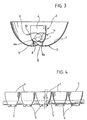
- the primary reflector 2 is formed by a plurality of cup-like elements 4 set alongside one another, having a generally parabolic surface, through which there extends said fluorescent lamp 1 in the way represented in greater detail in Figure 4.
- Each cup-like element 4 has a bottom 4a with a respective cusp 4b in a position corresponding to the lamp 1, and between the lamp 1 and the secondary reflector 3 a respective tubular appendage 5 engaged within a longitudinal opening 6 formed in the bottom wall 7 of the secondary reflector 3.
- the said opening 6 may be interrupted in the areas not occupied by the appendages 5 of the cup-like elements 4, and in this case the bottom wall 7 of the secondary reflector 3 will present, in positions corresponding to said areas, respective cusps 8 arranged in positions longitudinally corresponding to the lamp 1.
- the primary reflector 2 is completed by a perforated tile 9, which extends between each pair of contiguous cup-like elements 4 and is formed by two opposed curved flanges (10, 11).
- the secondary reflector 3 is constituted by an elongated tray-like element with a curved surface, the bottom wall 7 of which has the conformation described above.
- the cup-like elements 4 are tubular and devoid of appendages 5, and are engaged in corresponding holes 12 of the tile 9.
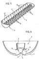
- the longitudinal opening 6 of the secondary reflector 3 can be eliminated, and the said secondary reflector 3 is conveniently formed by a plurality of tray-like elements 13 set alongside one another and normally made of a single piece.
- the device according to the invention can be set into a wall or ceiling (obviously, in the position corresponding to the one represented in Figure 2) or it can be set suspended.
- the secondary reflector 3 may be formed with openings (not illustrated).
Landscapes
- Engineering & Computer Science (AREA)
- General Engineering & Computer Science (AREA)
- Non-Portable Lighting Devices Or Systems Thereof (AREA)
- Optical Elements Other Than Lenses (AREA)
- Manufacture, Treatment Of Glass Fibers (AREA)
- Road Signs Or Road Markings (AREA)
- Endoscopes (AREA)
- Circuit Arrangement For Electric Light Sources In General (AREA)
Abstract
Description
- the primary reflector is formed by a plurality of cup-like elements set alongside one another, having a generally parabolic shape, through which there extends said light source; and
- the secondary reflector is constituted by a tray-like element with a curved surface, the bottom wall of which has a cusp in a position longitudinally corresponding to said light source.
- Figure 1 is a schematic perspective plan view from underneath of a controlled-luminance lighting device according to the invention;
- Figure 2 is a perspective top-plan view of the device;
- Figure 3 is a cross-sectional view at an enlarged scale of the device;
- Figure 4 is a partially sectioned side elevation of a part of the device illustrated in Figures 1 to 3;
- Figure 5 illustrates a variant of the device of Figure 1; and
- Figure 6 is a cross-sectional view at an enlarged scale of the device of Figure 5.
Claims (7)
- A controlled-luminance lighting device, comprising at least one fluorescent light source of a linear type (1), which extends longitudinally between a primary reflector (2) and a secondary reflector (3), characterized in that:the primary reflector (2) is formed by a plurality of cup-like elements (4) set alongside one another having a generally parabolic shape, through which there extends said light source (1); andthe secondary reflector (3) is constituted by a tray-like element with a curved surface, the bottom wall (7) of which has cusps (8) in a position longitudinally corresponding to said light source (1).
- The lighting device according to Claim 1, characterized in that said primary reflector (2) further includes a tile (9), which extends between each pair of contiguous cup-like elements (4) and is formed by two opposed curved flanges (10, 11).
- The lighting device according to Claim 1 or Claim 2, characterized in that said secondary reflector (3) is formed with a longitudinal opening (6).
- The lighting device according to Claim 3, characterized in that each of said cup-like elements (4) has a tubular appendage (5) set within said longitudinal opening (6) of the secondary reflector (3).
- The lighting device according to Claim 4, characterized in that each of said cup-like elements (4) has a bottom wall (4a) formed with a cusp (4b) in a position corresponding to said light source (1).
- The lighting device according to one or more of the preceding claims, characterized in that said tray-like element, which defines said secondary reflector (3), is defined by a plurality of tray-like elements (13) set alongside one another.
- The lighting device according to one or more of the preceding claims, characterized in that it is usable set in or suspended.
Applications Claiming Priority (2)
| Application Number | Priority Date | Filing Date | Title |
|---|---|---|---|
| IT2001TO000464A ITTO20010464A1 (en) | 2001-05-18 | 2001-05-18 | CONTROLLED LUMINANCE LIGHTING DEVICE. |
| ITTO20010464 | 2001-05-18 |
Publications (3)
| Publication Number | Publication Date |
|---|---|
| EP1262712A2 true EP1262712A2 (en) | 2002-12-04 |
| EP1262712A3 EP1262712A3 (en) | 2005-10-19 |
| EP1262712B1 EP1262712B1 (en) | 2006-08-02 |
Family
ID=11458865
Family Applications (1)
| Application Number | Title | Priority Date | Filing Date |
|---|---|---|---|
| EP02010657A Expired - Lifetime EP1262712B1 (en) | 2001-05-18 | 2002-05-13 | Controlled-luminance lighting device |
Country Status (6)
| Country | Link |
|---|---|
| US (1) | US6641282B2 (en) |
| EP (1) | EP1262712B1 (en) |
| AT (1) | ATE335163T1 (en) |
| DE (1) | DE60213513T2 (en) |
| ES (1) | ES2269549T3 (en) |
| IT (1) | ITTO20010464A1 (en) |
Cited By (6)
| Publication number | Priority date | Publication date | Assignee | Title |
|---|---|---|---|---|
| WO2003072997A1 (en) * | 2002-02-27 | 2003-09-04 | Ansorg Gmbh | Lighting device having a multitude of individual reflector elements |
| WO2004094897A1 (en) * | 2003-04-22 | 2004-11-04 | Zumtobel Staff Gmbh | Louvered luminaire |
| DE102004005917A1 (en) * | 2004-02-06 | 2005-08-25 | Zumtobel Staff Gmbh | Reflector arrangement for a luminaire with a plurality of reflector chambers arranged in series |
| WO2005090854A1 (en) * | 2004-03-12 | 2005-09-29 | Honeywell International Inc. | Luminaires for artificial lighting |
| WO2005103558A1 (en) * | 2004-04-19 | 2005-11-03 | Honeywell International Inc. | Luminaires with batwing light distribution |
| US7195374B2 (en) | 2004-03-12 | 2007-03-27 | Honeywell International, Inc. | Luminaires for artificial lighting |
Families Citing this family (22)
| Publication number | Priority date | Publication date | Assignee | Title |
|---|---|---|---|---|
| DE10151958A1 (en) * | 2001-10-22 | 2003-04-30 | Zumtobel Staff Gmbh | Luminaire with several pot reflectors |
| USD500384S1 (en) | 2002-12-17 | 2004-12-28 | Whelen Engineering Company, Inc. | Reflector for light assembly |
| JP2004259541A (en) * | 2003-02-25 | 2004-09-16 | Cateye Co Ltd | lighting equipment |
| DE602004020906D1 (en) * | 2003-09-19 | 2009-06-10 | Panasonic Corp | LIGHTING DEVICE |
| US7008079B2 (en) * | 2003-11-21 | 2006-03-07 | Whelen Engineering Company, Inc. | Composite reflecting surface for linear LED array |
| DE10360943A1 (en) * | 2003-12-23 | 2005-07-21 | Engel, Hartmut S. | lighting device |
| US7490961B2 (en) * | 2004-02-17 | 2009-02-17 | Focal Point, Llc | System of, and method for, indirect lighting |
| US7258467B2 (en) * | 2004-03-12 | 2007-08-21 | Honeywell International, Inc. | Low profile direct/indirect luminaires |
| US7279722B2 (en) * | 2005-10-21 | 2007-10-09 | Avago Technologies Ecbu Ip (Singapore) Pte Ltd | Light emitting device with adjustable reflector cup |
| EP2205900A2 (en) * | 2007-10-25 | 2010-07-14 | Koninklijke Philips Electronics N.V. | An elongated luminaire comprising leds for illuminating objects in front of the luminaire |
| USD633648S1 (en) * | 2008-01-31 | 2011-03-01 | Star Headlight & Lantern Co., Inc. | Face for optical element of a warning light module through which light generated in the module projects |
| DE202008010884U1 (en) * | 2008-07-17 | 2008-10-30 | Bega Gantenbrink-Leuchten Kg | lamp |
| US9052083B2 (en) * | 2008-10-31 | 2015-06-09 | Code 3, Inc. | Light fixture with inner and outer trough reflectors |
| USD612977S1 (en) * | 2009-05-05 | 2010-03-30 | Yi-jin Industrial Co., Ltd. | Rectangular lampshade |
| USD632421S1 (en) * | 2010-06-02 | 2011-02-08 | Star Headlight & Lantern Co., Inc. | Optical lens for projecting light from an LED light emitter |
| USD674965S1 (en) * | 2012-01-27 | 2013-01-22 | Hubbell Incorporated | LED optical component |
| USD687179S1 (en) * | 2012-07-31 | 2013-07-30 | Jung Hoon Kim | Protective cover for LED module |
| USD714993S1 (en) * | 2014-05-02 | 2014-10-07 | Thomas E Clendening | Indoor plant growing apparatus |
| USD753334S1 (en) * | 2014-10-16 | 2016-04-05 | Juluen Enterprise Co., Ltd. | Optical lens |
| USD774686S1 (en) | 2015-02-27 | 2016-12-20 | Star Headlight & Lantern Co., Inc. | Optical lens for projecting light from LED light emitters |
| USD775407S1 (en) | 2015-02-27 | 2016-12-27 | Star Headlight & Lantern Co., Inc. | Optical lens for projecting light from LED light emitters |
| US10208914B2 (en) * | 2015-09-09 | 2019-02-19 | Whelen Engineering Company, Inc. | Reflector with concentric interrupted reflecting surfaces |
Family Cites Families (6)
| Publication number | Priority date | Publication date | Assignee | Title |
|---|---|---|---|---|
| FR2476799A1 (en) * | 1980-02-27 | 1981-08-28 | Faccioli Gaspard | Reflector for luminescent or fluorescent light tube - has planar or V=shaped central section and two depending side wings |
| US4729075A (en) * | 1985-05-29 | 1988-03-01 | Brass John R | Constant zone reflector for luminaires and method |
| CH669830A5 (en) * | 1986-03-17 | 1989-04-14 | Peter A Balla | |
| DE9017372U1 (en) * | 1990-12-22 | 1991-04-04 | Großkinsky, Wilfried, 5000 Köln | Luminaire, especially ceiling or wall light |
| SE469804B (en) * | 1991-12-09 | 1993-09-13 | Fagerhults Ab | Reflector for an electric radiation luminaire and an electric radiation luminaire provided with such a reflector |
| WO1997045674A1 (en) * | 1996-05-30 | 1997-12-04 | Timothy Fohl | High aspect ratio light source controller |
-
2001
- 2001-05-18 IT IT2001TO000464A patent/ITTO20010464A1/en unknown
-
2002
- 2002-05-13 ES ES02010657T patent/ES2269549T3/en not_active Expired - Lifetime
- 2002-05-13 EP EP02010657A patent/EP1262712B1/en not_active Expired - Lifetime
- 2002-05-13 AT AT02010657T patent/ATE335163T1/en not_active IP Right Cessation
- 2002-05-13 DE DE60213513T patent/DE60213513T2/en not_active Expired - Fee Related
- 2002-05-16 US US10/145,885 patent/US6641282B2/en not_active Expired - Fee Related
Cited By (6)
| Publication number | Priority date | Publication date | Assignee | Title |
|---|---|---|---|---|
| WO2003072997A1 (en) * | 2002-02-27 | 2003-09-04 | Ansorg Gmbh | Lighting device having a multitude of individual reflector elements |
| WO2004094897A1 (en) * | 2003-04-22 | 2004-11-04 | Zumtobel Staff Gmbh | Louvered luminaire |
| DE102004005917A1 (en) * | 2004-02-06 | 2005-08-25 | Zumtobel Staff Gmbh | Reflector arrangement for a luminaire with a plurality of reflector chambers arranged in series |
| WO2005090854A1 (en) * | 2004-03-12 | 2005-09-29 | Honeywell International Inc. | Luminaires for artificial lighting |
| US7195374B2 (en) | 2004-03-12 | 2007-03-27 | Honeywell International, Inc. | Luminaires for artificial lighting |
| WO2005103558A1 (en) * | 2004-04-19 | 2005-11-03 | Honeywell International Inc. | Luminaires with batwing light distribution |
Also Published As
| Publication number | Publication date |
|---|---|
| ITTO20010464A1 (en) | 2002-11-18 |
| DE60213513T2 (en) | 2007-03-01 |
| EP1262712B1 (en) | 2006-08-02 |
| ATE335163T1 (en) | 2006-08-15 |
| US6641282B2 (en) | 2003-11-04 |
| EP1262712A3 (en) | 2005-10-19 |
| ITTO20010464A0 (en) | 2001-05-18 |
| DE60213513D1 (en) | 2006-09-14 |
| ES2269549T3 (en) | 2007-04-01 |
| US20020172046A1 (en) | 2002-11-21 |
Similar Documents
| Publication | Publication Date | Title |
|---|---|---|
| EP1262712B1 (en) | Controlled-luminance lighting device | |
| USD477891S1 (en) | Ceiling light | |
| CA2431946A1 (en) | Luminaire having a plurality of pot reflectors | |
| MD2505C2 (en) | Ceiling parabolic fluorescent lamp | |
| KR20090113828A (en) | Lighting fixtures | |
| EP1260760B1 (en) | Controlled-luminance lighting device | |
| US10774529B2 (en) | Ceiling tile with integrated lighting and ceiling system | |
| EP0045182B1 (en) | Compact fluorescent lamp | |
| FR2770026B3 (en) | FLUORESCENT TUBE WITH UNIFORM LIGHTING | |
| KR100989173B1 (en) | Reflector plate structure for high illuminance luminaire and high illuminance fixture | |
| JP2010092611A (en) | Reflector, and lighting device using the same | |
| CA2509302A1 (en) | Industrial up light reflector | |
| EP1376008A3 (en) | Lighting device | |
| DE3874182D1 (en) | GRID FOR FLUORESCENT LAMP LIGHTS. | |
| JP4410636B2 (en) | lighting equipment | |
| JP4352244B2 (en) | Recessed ceiling lighting fixture | |
| KR0119955Y1 (en) | Ceiling mounted fluorescent light fixture | |
| JPS6310567Y2 (en) | ||
| KR200236689Y1 (en) | an apparatus for suspending a compact fluorescent lamp | |
| ATE83547T1 (en) | LUMINAIRE WITH AT LEAST ONE BAR-SHAPED FLUORESCENT LAMP. | |
| JPS6030003A (en) | Illuminator | |
| JPH0364808A (en) | Liminaire | |
| TH39219A3 (en) | Lantern | |
| JPS61225707A (en) | Lighting apparatus | |
| JPH01137511A (en) | Lighting appliance |
Legal Events
| Date | Code | Title | Description |
|---|---|---|---|
| PUAI | Public reference made under article 153(3) epc to a published international application that has entered the european phase |
Free format text: ORIGINAL CODE: 0009012 |
|
| AK | Designated contracting states |
Kind code of ref document: A2 Designated state(s): AT BE CH CY DE DK ES FI FR GB GR IE IT LI LU MC NL PT SE TR |
|
| AX | Request for extension of the european patent |
Free format text: AL;LT;LV;MK;RO;SI |
|
| PUAL | Search report despatched |
Free format text: ORIGINAL CODE: 0009013 |
|
| AK | Designated contracting states |
Kind code of ref document: A3 Designated state(s): AT BE CH CY DE DK ES FI FR GB GR IE IT LI LU MC NL PT SE TR |
|
| AX | Request for extension of the european patent |
Extension state: AL LT LV MK RO SI |
|
| RIC1 | Information provided on ipc code assigned before grant |
Ipc: 7F 21V 7/00 B Ipc: 7F 21V 13/10 A Ipc: 7F 21V 11/02 B Ipc: 7F 21S 8/02 B Ipc: 7F 21S 8/04 B Ipc: 7F 21S 8/06 B Ipc: 7F 21S 8/00 B |
|
| GRAP | Despatch of communication of intention to grant a patent |
Free format text: ORIGINAL CODE: EPIDOSNIGR1 |
|
| 17P | Request for examination filed |
Effective date: 20051229 |
|
| GRAS | Grant fee paid |
Free format text: ORIGINAL CODE: EPIDOSNIGR3 |
|
| AKX | Designation fees paid |
Designated state(s): AT BE CH CY DE DK ES FI FR GB GR IE IT LI LU MC NL PT SE TR |
|
| GRAA | (expected) grant |
Free format text: ORIGINAL CODE: 0009210 |
|
| RIN1 | Information on inventor provided before grant (corrected) |
Inventor name: REPETTO, PIERMARIO Inventor name: CAPELLO, DAVIDE Inventor name: BOLLEA, DENIS Inventor name: PERLO, PIERO |
|
| AK | Designated contracting states |
Kind code of ref document: B1 Designated state(s): AT BE CH CY DE DK ES FI FR GB GR IE IT LI LU MC NL PT SE TR |
|
| PG25 | Lapsed in a contracting state [announced via postgrant information from national office to epo] |
Ref country code: IT Free format text: LAPSE BECAUSE OF FAILURE TO SUBMIT A TRANSLATION OF THE DESCRIPTION OR TO PAY THE FEE WITHIN THE PRESCRIBED TIME-LIMIT;WARNING: LAPSES OF ITALIAN PATENTS WITH EFFECTIVE DATE BEFORE 2007 MAY HAVE OCCURRED AT ANY TIME BEFORE 2007. THE CORRECT EFFECTIVE DATE MAY BE DIFFERENT FROM THE ONE RECORDED. Effective date: 20060802 Ref country code: FI Free format text: LAPSE BECAUSE OF FAILURE TO SUBMIT A TRANSLATION OF THE DESCRIPTION OR TO PAY THE FEE WITHIN THE PRESCRIBED TIME-LIMIT Effective date: 20060802 Ref country code: AT Free format text: LAPSE BECAUSE OF FAILURE TO SUBMIT A TRANSLATION OF THE DESCRIPTION OR TO PAY THE FEE WITHIN THE PRESCRIBED TIME-LIMIT Effective date: 20060802 Ref country code: BE Free format text: LAPSE BECAUSE OF FAILURE TO SUBMIT A TRANSLATION OF THE DESCRIPTION OR TO PAY THE FEE WITHIN THE PRESCRIBED TIME-LIMIT Effective date: 20060802 Ref country code: LI Free format text: LAPSE BECAUSE OF FAILURE TO SUBMIT A TRANSLATION OF THE DESCRIPTION OR TO PAY THE FEE WITHIN THE PRESCRIBED TIME-LIMIT Effective date: 20060802 Ref country code: NL Free format text: LAPSE BECAUSE OF FAILURE TO SUBMIT A TRANSLATION OF THE DESCRIPTION OR TO PAY THE FEE WITHIN THE PRESCRIBED TIME-LIMIT Effective date: 20060802 Ref country code: CH Free format text: LAPSE BECAUSE OF FAILURE TO SUBMIT A TRANSLATION OF THE DESCRIPTION OR TO PAY THE FEE WITHIN THE PRESCRIBED TIME-LIMIT Effective date: 20060802 |
|
| REG | Reference to a national code |
Ref country code: GB Ref legal event code: FG4D |
|
| REG | Reference to a national code |
Ref country code: CH Ref legal event code: EP |
|
| REG | Reference to a national code |
Ref country code: IE Ref legal event code: FG4D |
|
| REF | Corresponds to: |
Ref document number: 60213513 Country of ref document: DE Date of ref document: 20060914 Kind code of ref document: P |
|
| PG25 | Lapsed in a contracting state [announced via postgrant information from national office to epo] |
Ref country code: DK Free format text: LAPSE BECAUSE OF FAILURE TO SUBMIT A TRANSLATION OF THE DESCRIPTION OR TO PAY THE FEE WITHIN THE PRESCRIBED TIME-LIMIT Effective date: 20061102 |
|
| REG | Reference to a national code |
Ref country code: SE Ref legal event code: TRGR |
|
| NLV1 | Nl: lapsed or annulled due to failure to fulfill the requirements of art. 29p and 29m of the patents act | ||
| PG25 | Lapsed in a contracting state [announced via postgrant information from national office to epo] |
Ref country code: PT Free format text: LAPSE BECAUSE OF FAILURE TO SUBMIT A TRANSLATION OF THE DESCRIPTION OR TO PAY THE FEE WITHIN THE PRESCRIBED TIME-LIMIT Effective date: 20070102 |
|
| REG | Reference to a national code |
Ref country code: CH Ref legal event code: PL |
|
| ET | Fr: translation filed | ||
| REG | Reference to a national code |
Ref country code: ES Ref legal event code: FG2A Ref document number: 2269549 Country of ref document: ES Kind code of ref document: T3 |
|
| PGFP | Annual fee paid to national office [announced via postgrant information from national office to epo] |
Ref country code: SE Payment date: 20070508 Year of fee payment: 6 |
|
| PGFP | Annual fee paid to national office [announced via postgrant information from national office to epo] |
Ref country code: DE Payment date: 20070510 Year of fee payment: 6 |
|
| PLBE | No opposition filed within time limit |
Free format text: ORIGINAL CODE: 0009261 |
|
| STAA | Information on the status of an ep patent application or granted ep patent |
Free format text: STATUS: NO OPPOSITION FILED WITHIN TIME LIMIT |
|
| PGFP | Annual fee paid to national office [announced via postgrant information from national office to epo] |
Ref country code: ES Payment date: 20070621 Year of fee payment: 6 |
|
| 26N | No opposition filed |
Effective date: 20070503 |
|
| PGFP | Annual fee paid to national office [announced via postgrant information from national office to epo] |
Ref country code: GB Payment date: 20070509 Year of fee payment: 6 |
|
| PGFP | Annual fee paid to national office [announced via postgrant information from national office to epo] |
Ref country code: IT Payment date: 20070507 Year of fee payment: 6 |
|
| PG25 | Lapsed in a contracting state [announced via postgrant information from national office to epo] |
Ref country code: MC Free format text: LAPSE BECAUSE OF NON-PAYMENT OF DUE FEES Effective date: 20070531 |
|
| PG25 | Lapsed in a contracting state [announced via postgrant information from national office to epo] |
Ref country code: GR Free format text: LAPSE BECAUSE OF FAILURE TO SUBMIT A TRANSLATION OF THE DESCRIPTION OR TO PAY THE FEE WITHIN THE PRESCRIBED TIME-LIMIT Effective date: 20061103 |
|
| PGFP | Annual fee paid to national office [announced via postgrant information from national office to epo] |
Ref country code: FR Payment date: 20070510 Year of fee payment: 6 |
|
| PG25 | Lapsed in a contracting state [announced via postgrant information from national office to epo] |
Ref country code: IE Free format text: LAPSE BECAUSE OF NON-PAYMENT OF DUE FEES Effective date: 20070514 |
|
| GBPC | Gb: european patent ceased through non-payment of renewal fee |
Effective date: 20080513 |
|
| REG | Reference to a national code |
Ref country code: FR Ref legal event code: ST Effective date: 20090119 |
|
| PG25 | Lapsed in a contracting state [announced via postgrant information from national office to epo] |
Ref country code: FR Free format text: LAPSE BECAUSE OF NON-PAYMENT OF DUE FEES Effective date: 20080602 Ref country code: DE Free format text: LAPSE BECAUSE OF NON-PAYMENT OF DUE FEES Effective date: 20081202 |
|
| PG25 | Lapsed in a contracting state [announced via postgrant information from national office to epo] |
Ref country code: GB Free format text: LAPSE BECAUSE OF NON-PAYMENT OF DUE FEES Effective date: 20080513 |
|
| REG | Reference to a national code |
Ref country code: ES Ref legal event code: FD2A Effective date: 20080514 |
|
| PG25 | Lapsed in a contracting state [announced via postgrant information from national office to epo] |
Ref country code: CY Free format text: LAPSE BECAUSE OF FAILURE TO SUBMIT A TRANSLATION OF THE DESCRIPTION OR TO PAY THE FEE WITHIN THE PRESCRIBED TIME-LIMIT Effective date: 20060802 Ref country code: IT Free format text: LAPSE BECAUSE OF NON-PAYMENT OF DUE FEES Effective date: 20080513 Ref country code: LU Free format text: LAPSE BECAUSE OF NON-PAYMENT OF DUE FEES Effective date: 20070513 |
|
| PG25 | Lapsed in a contracting state [announced via postgrant information from national office to epo] |
Ref country code: TR Free format text: LAPSE BECAUSE OF FAILURE TO SUBMIT A TRANSLATION OF THE DESCRIPTION OR TO PAY THE FEE WITHIN THE PRESCRIBED TIME-LIMIT Effective date: 20060802 |
|
| PG25 | Lapsed in a contracting state [announced via postgrant information from national office to epo] |
Ref country code: ES Free format text: LAPSE BECAUSE OF NON-PAYMENT OF DUE FEES Effective date: 20080514 |
|
| PG25 | Lapsed in a contracting state [announced via postgrant information from national office to epo] |
Ref country code: SE Free format text: LAPSE BECAUSE OF NON-PAYMENT OF DUE FEES Effective date: 20080514 |