EP1262696B1 - Sealing arrangement for a turbomachine bearing - Google Patents
Sealing arrangement for a turbomachine bearing Download PDFInfo
- Publication number
- EP1262696B1 EP1262696B1 EP01870114A EP01870114A EP1262696B1 EP 1262696 B1 EP1262696 B1 EP 1262696B1 EP 01870114 A EP01870114 A EP 01870114A EP 01870114 A EP01870114 A EP 01870114A EP 1262696 B1 EP1262696 B1 EP 1262696B1
- Authority
- EP
- European Patent Office
- Prior art keywords
- ring
- support
- carbon ring
- bearing
- segmented
- Prior art date
- Legal status (The legal status is an assumption and is not a legal conclusion. Google has not performed a legal analysis and makes no representation as to the accuracy of the status listed.)
- Expired - Lifetime
Links
Images


Classifications
-
- F—MECHANICAL ENGINEERING; LIGHTING; HEATING; WEAPONS; BLASTING
- F16—ENGINEERING ELEMENTS AND UNITS; GENERAL MEASURES FOR PRODUCING AND MAINTAINING EFFECTIVE FUNCTIONING OF MACHINES OR INSTALLATIONS; THERMAL INSULATION IN GENERAL
- F16J—PISTONS; CYLINDERS; SEALINGS
- F16J15/00—Sealings
- F16J15/44—Free-space packings
- F16J15/441—Free-space packings with floating ring
- F16J15/442—Free-space packings with floating ring segmented
-
- F—MECHANICAL ENGINEERING; LIGHTING; HEATING; WEAPONS; BLASTING
- F16—ENGINEERING ELEMENTS AND UNITS; GENERAL MEASURES FOR PRODUCING AND MAINTAINING EFFECTIVE FUNCTIONING OF MACHINES OR INSTALLATIONS; THERMAL INSULATION IN GENERAL
- F16J—PISTONS; CYLINDERS; SEALINGS
- F16J15/00—Sealings
- F16J15/16—Sealings between relatively-moving surfaces
- F16J15/34—Sealings between relatively-moving surfaces with slip-ring pressed against a more or less radial face on one member
- F16J15/3404—Sealings between relatively-moving surfaces with slip-ring pressed against a more or less radial face on one member and characterised by parts or details relating to lubrication, cooling or venting of the seal
- F16J15/3408—Sealings between relatively-moving surfaces with slip-ring pressed against a more or less radial face on one member and characterised by parts or details relating to lubrication, cooling or venting of the seal at least one ring having an uneven slipping surface
- F16J15/3412—Sealings between relatively-moving surfaces with slip-ring pressed against a more or less radial face on one member and characterised by parts or details relating to lubrication, cooling or venting of the seal at least one ring having an uneven slipping surface with cavities
- F16J15/342—Sealings between relatively-moving surfaces with slip-ring pressed against a more or less radial face on one member and characterised by parts or details relating to lubrication, cooling or venting of the seal at least one ring having an uneven slipping surface with cavities with means for feeding fluid directly to the face
Definitions
- the present invention relates to a seal seal for a turbomachine bearing.
- gaskets for turbomachine bearing housings that include a bearing mounted between a sleeve integral with a shaft, a bearing bracket, a seal bracket and which serve to delimit the oil chamber of the bearing of the enclosure to Air turbomachine, is well known in itself. It exists essentially two types of such joints, on the one hand radial seals, with or without contact, and on the other hand axial joints.
- the present invention aims at enabling solve the problems of the state of the art.
- the present invention aims to enable the control of air leaks from the air chamber to the oil chamber while preventing oil leakage from the oil chamber to the air enclosure does not produce and this regardless of the configurations of theft, even in case of reverse pressure.
- the present invention further aims to allow the control of the heating of the joints by the friction and therefore reduce wear.
- the present invention aims to enable a solution that allows to increase the service life of such joints.
- the present invention therefore aims to propose the use of segmented axial carbon seals having a lift in a turbomachine bearing which to solve the various problems of the state of the technique.
- the present invention relates to a seal device for a bearing turbomachine which comprises a bearing mounted on a sleeve attached to a tree, as well as a bearing support, a seal support, said bearing for separating the oil chamber of the bearing of an air chamber of the turbomachine, said seal device comprising a support, a rotating ring mounted on the part of the sleeve located on the side of the oil chamber, a carbon ring segmentation allowing the injection of parietal air between junctions of successive segments of the carbon ring, a axial locking system and anti-rotation of the ring of carbon allowing this carbon ring to stay on its support in the free state and in operation, said locking system not having contact with the tree and with the support, the segmented carbon ring being pressed axially in the free state against the ring rotating by springs and presenting on their face radial a cooperative parietal air injection system with the ring rotating by the radial face, the ring rotating cooperating with the segments of the carbon ring
- a semi-static seal is obtained by compressing the segments of the ring of carbon against the support using at least one spring of circular expansion housed in a groove, this semi-static sealing being machined directly on the segmented carbon ring.
- the rotating ring is held axially by a spring in Belle Ville type ring, centered on the sleeve using Belle's Spring Compression Control System City through an elastic seal, this ring rotating being driven in rotation by pins of a antirotation and axial locking system ensures the blocking of this carbon ring in the free state.
- the embodiments described above allow the realization of a parietal injection of air through the junction of segments to promote the lift effect.
- the present invention will advantageously also to support displacements axial or radial of the tree.
- the present invention allows very specific uses like applications to very high or very low temperatures Cryogenic).
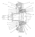
- FIG. 1 represents, according to a view in cut, by a plane passing through the axis of rotation of the shaft, a turbomachine bearing part comprising a sealing device according to the invention
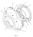
- Figure 2 shows a front view enlarged segmented carbon ring for static seals
- Fig 3 shows a view from the back enlarged segmented carbon ring for static seals
- FIG. 4 represents an exploded view of the segmented axial carbon seal with lift and injection parietal according to the present invention.
- Figure 1 represents a bearing in which we represent a casing (1) or support of the static part of the seal with holes (24) for discharging particles, a ring of carbon (2) segmented with tiered overlap and injection of parietal air, an axial locking system and antirotation (6) which allows the carbon ring (2) to remain in his support (1) in the free state and in functioning, a rotating ring (3) carbide or coated of carbide with grooves generating a lift effect on the contact surface (19) cooperating with the surface (20) of the segmented carbon ring (2).
- the rotating ring (3) is centered but not fixed on a sleeve (15), which is fixed on the shaft (16), to by means of an elastic seal (5) allowing non-centering tightening of the rotating ring (3) and resistant to operating temperatures.
- the whole is in front a bearing (8) itself is mounted on a support (10).
- the rotating ring (3) is driven by anti-rotation locking pins (12) and is maintained only in axial displacement by a ring spring (4) for example Belle Ville type and a system of cartridges controlled compression (9) to ensure proper compression of the ring spring (4).
- a ring spring (4) for example Belle Ville type and a system of cartridges controlled compression (9) to ensure proper compression of the ring spring (4).
- Axial load to maintain contact between the segmented carbon ring (2) and the rotating ring (3) in the free state is obtained by the application of axial springs (7).
- This static seal is provided by a circular expansion spring (21) housed in a groove (23) which makes contact between the ring of carbon (2) segmented and the support of the joint (1).
- An air chamber (18) ensures the air-side pressurization of the segmented carbon ring (2) and an oil chamber (17) provides pressure on the oil side of the landing.
- a seal support (11) secures the attachment of the envelope (1) or support with a setting of compression of the carbon ring (2) segmented by the presence of a wedge (25) and thus separates the air chamber (18) of the oil chamber (17).
Description
La présente invention se rapporte à un joint d'étanchéité destiné à un palier de turbomachine.The present invention relates to a seal seal for a turbomachine bearing.
L'utilisation de joints d'étanchéité pour des enceintes de palier de turbomachines qui comprennent un roulement monté entre un manchon solidaire d'un arbre, un support de palier, un support de joint et qui servent à délimiter l'enceinte à huile du roulement de l'enceinte à air de la turbomachine, est bien connue en soi. Il existe essentiellement deux types de tels joints, d'une part des joints radiaux, avec ou sans contact, et d'autre part des joints axiaux.The use of gaskets for turbomachine bearing housings that include a bearing mounted between a sleeve integral with a shaft, a bearing bracket, a seal bracket and which serve to delimit the oil chamber of the bearing of the enclosure to Air turbomachine, is well known in itself. It exists essentially two types of such joints, on the one hand radial seals, with or without contact, and on the other hand axial joints.
En particulier, on connaít par les documents EP-0818607, US-3874677, EP-0387122, EP-0491624, EP-1055848 de tels types de joints radiaux.In particular, we know from the documents EP-0818607, US-3874677, EP-0387122, EP-0491624, EP-1055848 such types of radial seals.
De même, les documents EP-0967424 et US-4398730 décrivent de tels joints axiaux.Similarly, documents EP-0967424 and US-4398730 describe such axial joints.
L'utilisation de tels joints axiaux ou radiaux, avec ou sans contact, réduit largement les fuites d'air vers les enceintes à huile et en conséquence la consommation d'huile après passage au travers d'un déshuileur.The use of such axial joints or radial, with or without contact, greatly reduces leakage air to the oil chambers and consequently the oil consumption after passing through a oiler.
Cependant, les répercussions des balourds de l'arbre ne sont pas maítrisées, des usures résultant de frottements importants peuvent apparaítre, ce qui bien entendu limite la durée de vie de tels joints.However, the consequences of unbalance the tree are not controlled, wear resulting from important friction can appear, which understood limits the life of such joints.
Ceci est d'autant plus le cas que, pour des applications particulières, les durées de vie (fréquemment de l'ordre de quelques milliers d'heures) sont nettement insuffisantes.This is all the more the case that, for particular applications, lifespans (frequently of the order of a few thousand hours) are clearly insufficient.
La présente invention vise à permettre de résoudre les problèmes de l'état de la technique. En particulier, la présente invention vise à permettre le contrôle des fuites d'air de l'enceinte à air vers l'enceinte à huile tout en évitant que les fuites d'huile de l'enceinte à huile vers l'enceinte à air ne se produisent et ceci quelles que soient les configurations de vol y compris en cas de pression inverse.The present invention aims at enabling solve the problems of the state of the art. In In particular, the present invention aims to enable the control of air leaks from the air chamber to the oil chamber while preventing oil leakage from the oil chamber to the air enclosure does not produce and this regardless of the configurations of theft, even in case of reverse pressure.
La présente invention vise en outre à permettre le contrôle de l'échauffement des joints par les frottements et donc de diminuer l'usure.The present invention further aims to allow the control of the heating of the joints by the friction and therefore reduce wear.
La présente invention vise enfin à permettre une solution qui permette d'augmenter la durée de vie de tels joints.Finally, the present invention aims to enable a solution that allows to increase the service life of such joints.
La présente invention vise donc à proposer l'utilisation de joints de carbone axiaux segmentés présentant une portance dans un palier de turbomachine qui permette de résoudre les différents problèmes de l'état de la technique.The present invention therefore aims to propose the use of segmented axial carbon seals having a lift in a turbomachine bearing which to solve the various problems of the state of the technique.
La présente invention se rapporte à un dispositif de joint d'étanchéité destiné à un palier turbomachine qui comporte un roulement monté sur un manchon solidaire d'un arbre, ainsi qu'un support de palier, un support de joint, ledit palier permettant de séparer l'enceinte à huile du roulement d'une enceinte à air de la turbomachine, ledit dispositif de joint comprenant un support, un anneau tournant monté sur la partie du manchon située du côté de l'enceinte à huile, un anneau de carbone segmenté permettant l'injection d'air pariétal entre les jonctions de segments successifs de l'anneau de carbone, un système de blocage axial et antirotation de l'anneau de carbone permettant à cet anneau de carbone de rester sur son support à l'état libre et en fonctionnement, ledit système de blocage ne présentant pas de contact avec l'arbre et avec le support, l'anneau de carbone segmenté étant appuyé axialement à l'état libre contre l'anneau tournant par des ressorts et présentant sur leur face radiale un système d'injection d'air pariétal coopérant avec l'anneau tournant par la face radiale, l'anneau tournant coopérant avec les segments de l'anneau de carbone de manière à réaliser des rainures de portance qui permettent d'assurer l'étanchéité dynamique en fonctionnement sans frottement entre les faces radiales. Cet effet de portance permet de supprimer le frottement entre les différents segments de l'anneau de carbone et l'anneau tournant en contrôlant le débit de fuite d'air et permet ainsi d'augmenter la durée de vie du joint de manière quasi infinie.The present invention relates to a seal device for a bearing turbomachine which comprises a bearing mounted on a sleeve attached to a tree, as well as a bearing support, a seal support, said bearing for separating the oil chamber of the bearing of an air chamber of the turbomachine, said seal device comprising a support, a rotating ring mounted on the part of the sleeve located on the side of the oil chamber, a carbon ring segmentation allowing the injection of parietal air between junctions of successive segments of the carbon ring, a axial locking system and anti-rotation of the ring of carbon allowing this carbon ring to stay on its support in the free state and in operation, said locking system not having contact with the tree and with the support, the segmented carbon ring being pressed axially in the free state against the ring rotating by springs and presenting on their face radial a cooperative parietal air injection system with the ring rotating by the radial face, the ring rotating cooperating with the segments of the carbon ring in order to achieve lift grooves which allow for dynamic sealing in operation without friction between the radial faces. This lift effect helps to eliminate friction between the different segments of the carbon ring and the rotating ring by controlling the air leakage rate and thus makes it possible to increase the life of the seal of almost infinite way.
De préférence, une étanchéité semi-statique est obtenue par la compression des segments de l'anneau de carbone contre le support à l'aide d'au moins un ressort d'expansion circulaire logé dans une gorge, cette étanchéité semi-statique étant usinée directement sur l'anneau de carbone segmenté.Preferably, a semi-static seal is obtained by compressing the segments of the ring of carbon against the support using at least one spring of circular expansion housed in a groove, this semi-static sealing being machined directly on the segmented carbon ring.
Selon une forme d'exécution préférée, l'anneau tournant est maintenu axialement par un ressort en anneau de type Belle Ville, centré sur le manchon à l'aide d'un système de contrôle de compression du ressort de Belle Ville par l'intermédiaire d'un joint élastique, cet anneau tournant étant entraíné en rotation par des goupilles d'un système de blocage antirotation et axial permet d'assurer le blocage de cet anneau de carbone à l'état libre.According to a preferred embodiment, the rotating ring is held axially by a spring in Belle Ville type ring, centered on the sleeve using Belle's Spring Compression Control System City through an elastic seal, this ring rotating being driven in rotation by pins of a antirotation and axial locking system ensures the blocking of this carbon ring in the free state.
Avantageusement, les formes d'exécution décrites ci-dessus permettent la réalisation d'une injection pariétale de l'air à travers la jonction des segments en vue de favoriser l'effet de portance.Advantageously, the embodiments described above allow the realization of a parietal injection of air through the junction of segments to promote the lift effect.
Ceci permet en outre d'obtenir une très faible fuite d'air de l'enceinte d'air vers l'enceinte d'huile tout en évitant qu'il y ait de fuites d'huile de l'enceinte d'huile vers l'enceinte d'air et ceci pour toutes les configurations de vol y compris en cas de pression inverse.This also makes it possible to obtain a very low air leakage from the air enclosure to the enclosure of oil while preventing oil leaks from the oil chamber to the air chamber and this for all flight configurations including in case of reverse pressure.
En outre, on observe ainsi une très faible consommation d'huile à travers les déshuileurs.In addition, we observe a very weak oil consumption through de-oilers.
La présente invention permettra avantageusement également de supporter les déplacements axiaux ou radiaux de l'arbre.The present invention will advantageously also to support displacements axial or radial of the tree.
Enfin, la présente invention permet des utilisations très spécifiques comme des applications à très hautes ou à très basses températures (températures cryogéniques).Finally, the present invention allows very specific uses like applications to very high or very low temperatures Cryogenic).
Enfin, on observe avantageusement par le manque de frottement une usure relativement restreinte et donc une augmentation de la durée de vie importante pour un tel joint.Finally, it is advantageous to observe lack of friction relatively little wear and therefore an increase in the long life span for a such seal.
Les caractéristiques et avantages de l'invention seront mieux compris en se référant aux figures annexées dans lesquelles :Features and benefits of the invention will be better understood with reference to the figures annexed in which:
La figure 1 représente, selon une vue en coupe, par un plan passant par l'axe de rotation de l'arbre, une partie de palier de turbomachine comportant un dispositif de joint d'étanchéité conforme à l'invention ;FIG. 1 represents, according to a view in cut, by a plane passing through the axis of rotation of the shaft, a turbomachine bearing part comprising a sealing device according to the invention;
La figure 2 représente une vue de face agrandie de l'anneau de carbone segmenté pour des étanchéités statiques ;Figure 2 shows a front view enlarged segmented carbon ring for static seals;
La figue 3 représente une vue par l'arrière agrandie de l'anneau de carbone segmenté pour des étanchéités statiques ;Fig 3 shows a view from the back enlarged segmented carbon ring for static seals;
La figure 4 représente une vue éclatée du joint de carbone axial segmenté avec portance et injection pariétale selon la présente invention.FIG. 4 represents an exploded view of the segmented axial carbon seal with lift and injection parietal according to the present invention.
La présente invention sera décrite en se référant aux figures annexées. En particulier la figure 1 représente un palier dans lequel on représente une enveloppe (1) ou support de la partie statique du joint avec des trous (24) de décharge de particules, un anneau de carbone (2) segmenté avec recouvrement étagé et injection d'air pariétale, un système de blocage axial et antirotation (6) qui permet à l'anneau de carbone (2) de rester dans son support (1) à l'état libre et en fonctionnement, un anneau tournant (3) en carbure ou revêtu de carbure avec des rainures générant un effet de portance sur la surface de contact (19) coopérant avec la surface (20) de l'anneau de carbone (2) segmenté.The present invention will be described by referring to the appended figures. In particular Figure 1 represents a bearing in which we represent a casing (1) or support of the static part of the seal with holes (24) for discharging particles, a ring of carbon (2) segmented with tiered overlap and injection of parietal air, an axial locking system and antirotation (6) which allows the carbon ring (2) to remain in his support (1) in the free state and in functioning, a rotating ring (3) carbide or coated of carbide with grooves generating a lift effect on the contact surface (19) cooperating with the surface (20) of the segmented carbon ring (2).
L'anneau tournant (3) est centré mais non fixé sur un manchon (15), qui est fixé sur l'arbre (16), à l'aide d'un joint élastique (5) permettant le centrage non serrant de l'anneau tournant (3) et résistant aux températures de fonctionnement. L'ensemble se trouve devant un roulement (8) lui-même est monté sur un support (10).The rotating ring (3) is centered but not fixed on a sleeve (15), which is fixed on the shaft (16), to by means of an elastic seal (5) allowing non-centering tightening of the rotating ring (3) and resistant to operating temperatures. The whole is in front a bearing (8) itself is mounted on a support (10).
L'anneau tournant (3) est entraíné par des goupilles de blocage antirotation (12) et est maintenu seulement en déplacement axial par un ressort en anneau (4) par exemple de type Belle Ville et un système de cartouches de compression contrôlée (9) afin d'assurer la bonne compression du ressort en anneau (4).The rotating ring (3) is driven by anti-rotation locking pins (12) and is maintained only in axial displacement by a ring spring (4) for example Belle Ville type and a system of cartridges controlled compression (9) to ensure proper compression of the ring spring (4).
Une charge axiale pour maintenir le contact entre l'anneau de carbone (2) segmenté et l'anneau tournant (3) à l'état libre est obtenue par l'application de ressorts axiaux (7).Axial load to maintain contact between the segmented carbon ring (2) and the rotating ring (3) in the free state is obtained by the application of axial springs (7).
L'étanchéité semi-statique secondaire (22), usinée directement dans l'anneau de carbone (2) segmenté, présente les températures limites de fonctionnement de l'anneau de carbone (2) segmenté. Cette étanchéité statique est assurée par un ressort d'expansion circulaire (21) logé dans une gorge (23) qui réalise le contact entre l'anneau de carbone (2) segmenté et le support du joint (1).Semi-static secondary sealing (22), machined directly into the segmented carbon ring (2), presents the operating limit temperatures of the carbon ring (2) segmented. This static seal is provided by a circular expansion spring (21) housed in a groove (23) which makes contact between the ring of carbon (2) segmented and the support of the joint (1).
L'effet de portance générant sur l'interface de la surface de contact (19) de l'anneau tournant (3) et la surface (20) de l'anneau de carbone (2) segmenté est assuré par les rainures de portance (13) et l'injection d'air pariétale à travers la jonction (14) entre les segments de carbone.The lift effect generating on the interface of the contact surface (19) of the rotating ring (3) and the surface (20) of the segmented carbon ring (2) is ensured by the lift grooves (13) and the injection of parietal air through the junction (14) between carbon segments.
Une enceinte à air (18) assure la pressurisation côté air de l'anneau de carbone (2) segmenté et une enceinte à huile (17) assure la pression côté huile du palier.An air chamber (18) ensures the air-side pressurization of the segmented carbon ring (2) and an oil chamber (17) provides pressure on the oil side of the landing.
Un support de joint (11) assure la fixation de l'enveloppe (1) ou support avec un réglage de la compression de l'anneau de carbone (2) segmenté par la présence d'une cale (25) et sépare ainsi l'enceinte à air (18) de l'enceinte à huile (17).A seal support (11) secures the attachment of the envelope (1) or support with a setting of compression of the carbon ring (2) segmented by the presence of a wedge (25) and thus separates the air chamber (18) of the oil chamber (17).
Claims (3)
- Sealing joint device for a turbomachine bearing comprising a rolling bearing (8) mounted on a sleeve (15) fastened to a shaft (16) and a bearing support (10), a joint support (11), said bearing allowing to separate the oil chamber (17) of the rolling bearing from an air chamber (18) of a turbomachine, said joint device comprising a support (1), a rotary ring (3) that can be fixed onto the part of the sleeve (15) located on the side of the oil chamber (17), characterised by a segmented carbon ring (2) allowing the injection of parietal air through junctions (14) between the successive carbon segments (2), an axial anti-rotation blocking system (6) of the segmented carbon ring (2) allowing this segmented carbon ring (2) to remain on its support (1) in the free state and in operation, said blocking system (6) presenting no contact with the shaft (16) and the support (1), the segmented carbon ring (2) being axially leaning in the free state against the rotary ring (3) by springs (7) and presenting on its radial face (20) an injection system for parietal air co-operating with the rotary ring (3) by the radial face (19), the rotary ring (3) co-operating with the segments of the carbon ring (2) so as to achieve lift slots (13) that allow to ensure dynamic seal in operation without friction between the radial faces (19, 20).
- Sealing joint device according to Claim 1, characterised in that semi-static sealing (22) is obtained by compressing the segments of the carbon ring (2) against the support (1) by means of at least one annular expansion spring (21) housed in a groove (23), this semi-static sealing being directly machined on the segmented carbon ring (2).
- Sealing joint device according to Claim 1 or 2, characterised in that the rotary ring (3) is axially maintained by an annular spring of the Belle Ville type, centred on the sleeve (15) by means of a control system for the compression (9) of the Belle Ville spring via an elastic joint (5), this rotary ring (3) being rotated by pins (12).
Priority Applications (3)
| Application Number | Priority Date | Filing Date | Title |
|---|---|---|---|
| EP01870114A EP1262696B1 (en) | 2001-05-30 | 2001-05-30 | Sealing arrangement for a turbomachine bearing |
| DE60113069T DE60113069T2 (en) | 2001-05-30 | 2001-05-30 | Sealing arrangement for turbomachinery bearings |
| US10/158,205 US20020180156A1 (en) | 2001-05-30 | 2002-05-28 | Axial sealing device for a turbomachine bearing |
Applications Claiming Priority (1)
| Application Number | Priority Date | Filing Date | Title |
|---|---|---|---|
| EP01870114A EP1262696B1 (en) | 2001-05-30 | 2001-05-30 | Sealing arrangement for a turbomachine bearing |
Publications (2)
| Publication Number | Publication Date |
|---|---|
| EP1262696A1 EP1262696A1 (en) | 2002-12-04 |
| EP1262696B1 true EP1262696B1 (en) | 2005-08-31 |
Family
ID=8184978
Family Applications (1)
| Application Number | Title | Priority Date | Filing Date |
|---|---|---|---|
| EP01870114A Expired - Lifetime EP1262696B1 (en) | 2001-05-30 | 2001-05-30 | Sealing arrangement for a turbomachine bearing |
Country Status (3)
| Country | Link |
|---|---|
| US (1) | US20020180156A1 (en) |
| EP (1) | EP1262696B1 (en) |
| DE (1) | DE60113069T2 (en) |
Families Citing this family (9)
| Publication number | Priority date | Publication date | Assignee | Title |
|---|---|---|---|---|
| CN101749719B (en) * | 2010-02-10 | 2012-03-07 | 无锡华光锅炉股份有限公司 | Sealing device between boiler connecting rod and air chamber |
| WO2012022550A2 (en) * | 2010-07-21 | 2012-02-23 | Siemens Aktiengesellschaft | Sealing device |
| US8348280B2 (en) * | 2010-10-22 | 2013-01-08 | General Electric Company | Seal apparatus |
| US9534502B2 (en) * | 2014-03-26 | 2017-01-03 | General Electric Company | Individually compliant segments for split ring hydrodynamic face seal |
| US20170307019A1 (en) * | 2014-10-07 | 2017-10-26 | Dresser-Rand SAS | Seal Assembly For A Turbomachine |
| JP2016114131A (en) * | 2014-12-12 | 2016-06-23 | 三菱日立パワーシステムズ株式会社 | Seal device, rotary machine and method for manufacturing the seal device |
| US11371373B2 (en) | 2019-10-29 | 2022-06-28 | Raytheon Technologies Corporation | Seal assembly for use in gas turbine engines |
| CN112762173B (en) * | 2021-01-18 | 2023-06-20 | 洛阳佰工工业密封有限公司 | Mechanical seal assembly structure capable of avoiding oil seal leakage |
| CN113405735B (en) * | 2021-04-30 | 2022-11-11 | 北京航天动力研究所 | High-speed helium end face sealing test device for liquid rocket engine turbine pump |
Family Cites Families (23)
| Publication number | Priority date | Publication date | Assignee | Title |
|---|---|---|---|---|
| US3347553A (en) * | 1966-05-23 | 1967-10-17 | Gen Electric | Fluid seal |
| US3575424A (en) * | 1969-11-28 | 1971-04-20 | Koppers Co Inc | Pressure balanced circumferential seal assembly |
| US3758179A (en) * | 1971-09-24 | 1973-09-11 | Basil Smith Seals Ltd | Mechanical shaft seal |
| US3874677A (en) | 1973-07-19 | 1975-04-01 | Nasa | High speed, self-acting shaft seal |
| US4213618A (en) * | 1978-05-24 | 1980-07-22 | Mechanical Seal & Service, Inc. | Self-contained rotary mechanical seals |
| US4285526A (en) * | 1979-09-25 | 1981-08-25 | Stefa Industri Aktiebolag | Sealing device for bearings, especially roll bearings |
| DE3119467C2 (en) | 1981-05-15 | 1983-09-01 | MTU Motoren- und Turbinen-Union München GmbH, 8000 München | Mechanical seal with dynamic gas lubrication for high-speed turbo machines, especially gas turbine engines |
| US4578018A (en) * | 1983-06-20 | 1986-03-25 | General Electric Company | Rotor thrust balancing |
| US4687346A (en) * | 1986-09-02 | 1987-08-18 | United Technologies Corporation | Low profile bearing support structure |
| FR2644205B1 (en) | 1989-03-08 | 1991-05-03 | Snecma | TURBOMACHINE BEARING WITH INTEGRATED SEAL |
| US5058904A (en) * | 1990-02-21 | 1991-10-22 | Eg&G Sealol Inc. | Self-contained sealing ring assembly |
| FR2670830B1 (en) | 1990-12-19 | 1994-12-02 | Snecma | SEALING SYSTEM FOR A MACHINE BEARING, PARTICULARLY A TURBOMACHINE. |
| US5145189A (en) * | 1991-09-11 | 1992-09-08 | General Electric Company | Hydro-lift dynamic circumferential seal |
| US5301957A (en) * | 1992-04-27 | 1994-04-12 | General Electric Company | Expanding circumferential seal with upper-cooled runner |
| AU676466B2 (en) * | 1993-03-09 | 1997-03-13 | Robert Mconie | Flexible drive split mechanical seal |
| US5516118A (en) * | 1993-07-19 | 1996-05-14 | Stein Seal Company | Circumferential hydrodynamic seals for sealing a bidirectionally rotatable member |
| US5509664A (en) * | 1993-07-19 | 1996-04-23 | Stein Seal Company | Segmented hydrodynamic seals for sealing a rotatable shaft |
| US5813830A (en) | 1996-02-09 | 1998-09-29 | Allison Engine Company, Inc. | Carbon seal contaminant barrier system |
| US5820129A (en) * | 1996-07-11 | 1998-10-13 | Power Packing Co., Inc. | Mechanical split double seals |
| US6131912A (en) * | 1997-12-17 | 2000-10-17 | A.W. Chesterton Company | Split mechanical face seal |
| DE69822443T2 (en) | 1998-06-26 | 2005-01-20 | Techspace Aero, Milmort | Turbomachine device with a gasket |
| JP3650954B2 (en) * | 1998-09-18 | 2005-05-25 | イーグル工業株式会社 | Non-contact mechanical seal for high speed |
| EP1055848B1 (en) | 1999-05-26 | 2004-08-25 | Techspace Aero | Sealing arrangement with lift for a turbomachine bearing chamber |
-
2001
- 2001-05-30 DE DE60113069T patent/DE60113069T2/en not_active Expired - Lifetime
- 2001-05-30 EP EP01870114A patent/EP1262696B1/en not_active Expired - Lifetime
-
2002
- 2002-05-28 US US10/158,205 patent/US20020180156A1/en not_active Abandoned
Also Published As
| Publication number | Publication date |
|---|---|
| EP1262696A1 (en) | 2002-12-04 |
| DE60113069T2 (en) | 2006-06-08 |
| DE60113069D1 (en) | 2005-10-06 |
| US20020180156A1 (en) | 2002-12-05 |
Similar Documents
| Publication | Publication Date | Title |
|---|---|---|
| EP2870323B1 (en) | Gasket device for the bearing of a turbomachine, comprising two elastic seals | |
| CA2552667C (en) | Tandem dual element intershaft carbon seal | |
| EP0967424B1 (en) | Turbomachine arrangement with a sealing arrangement | |
| US5029875A (en) | Fluid seal structure | |
| US5351971A (en) | Brush seal device having a floating backplate | |
| FR2973440A1 (en) | MECHANICAL ASPIRATION TRIM AND METHOD THEREOF | |
| EP0568192A1 (en) | Secondary seal for gas turbines | |
| EP1262696B1 (en) | Sealing arrangement for a turbomachine bearing | |
| FR2879649A1 (en) | REMOVABLE ABRASIVE JOINT SUPPORTS FOR SEALING BETWEEN ROTARY AND FIXED TURBINE ORGANS. | |
| EP1167788A1 (en) | Sealing device of a squeeze film damper incorporated in a rolling element bearing | |
| FR2674930A1 (en) | Stationary sealing ring assembly intended to be used in dry-face gas joint assemblies | |
| FR2902172A1 (en) | SUCTION LABYRINTH SEAL | |
| CA2094591A1 (en) | Sear rotor | |
| US5399024A (en) | Face seal with hydrodynamic thrust pads | |
| EP1174629A1 (en) | Sealing device of a squeeze film damper incorporated in a rolling element bearing | |
| EP1055848B1 (en) | Sealing arrangement with lift for a turbomachine bearing chamber | |
| FR2602847A1 (en) | Sealing system for a shaft revolving in a support element | |
| EP0500884A1 (en) | Sealing device between the cylinder head and the cylinder lining. | |
| EP1186813B1 (en) | Contactless axial carbon seal for a bearing housing | |
| FR2888877A1 (en) | Vibration dampening device for aircraft, has dampening rod formed by split ring and self balanced in rotation using reduction of rod`s section in zone that is diametrically opposite to ends with respect to rotational axis | |
| JP2002122243A (en) | Split type seal | |
| JP2006002768A (en) | Hydraulic motor having propelling member held sealedly to relevant contacting surface by internal resilient means and capable of being drawn out and inserted | |
| EP1170520A2 (en) | Rolling element bearing provided with a squeeze film damper | |
| EP1188972A1 (en) | Contactless axial carbon seal for a bearing housing | |
| FR2520469A1 (en) | MECHANICAL FRONTAL JOINT |
Legal Events
| Date | Code | Title | Description |
|---|---|---|---|
| PUAI | Public reference made under article 153(3) epc to a published international application that has entered the european phase |
Free format text: ORIGINAL CODE: 0009012 |
|
| AK | Designated contracting states |
Kind code of ref document: A1 Designated state(s): AT BE CH CY DE DK ES FI FR GB GR IE IT LI LU MC NL PT SE TR |
|
| AX | Request for extension of the european patent |
Free format text: AL;LT;LV;MK;RO;SI |
|
| 17P | Request for examination filed |
Effective date: 20030317 |
|
| AKX | Designation fees paid |
Designated state(s): BE DE FR GB |
|
| GRAP | Despatch of communication of intention to grant a patent |
Free format text: ORIGINAL CODE: EPIDOSNIGR1 |
|
| GRAP | Despatch of communication of intention to grant a patent |
Free format text: ORIGINAL CODE: EPIDOSNIGR1 |
|
| GRAS | Grant fee paid |
Free format text: ORIGINAL CODE: EPIDOSNIGR3 |
|
| GRAA | (expected) grant |
Free format text: ORIGINAL CODE: 0009210 |
|
| AK | Designated contracting states |
Kind code of ref document: B1 Designated state(s): BE DE FR GB |
|
| REG | Reference to a national code |
Ref country code: GB Ref legal event code: FG4D Free format text: NOT ENGLISH |
|
| REF | Corresponds to: |
Ref document number: 60113069 Country of ref document: DE Date of ref document: 20051006 Kind code of ref document: P |
|
| GBT | Gb: translation of ep patent filed (gb section 77(6)(a)/1977) |
Effective date: 20050928 |
|
| PLBE | No opposition filed within time limit |
Free format text: ORIGINAL CODE: 0009261 |
|
| STAA | Information on the status of an ep patent application or granted ep patent |
Free format text: STATUS: NO OPPOSITION FILED WITHIN TIME LIMIT |
|
| 26N | No opposition filed |
Effective date: 20060601 |
|
| REG | Reference to a national code |
Ref country code: FR Ref legal event code: PLFP Year of fee payment: 16 |
|
| PGFP | Annual fee paid to national office [announced via postgrant information from national office to epo] |
Ref country code: DE Payment date: 20160421 Year of fee payment: 16 Ref country code: GB Payment date: 20160426 Year of fee payment: 16 |
|
| REG | Reference to a national code |
Ref country code: FR Ref legal event code: PLFP Year of fee payment: 17 |
|
| REG | Reference to a national code |
Ref country code: DE Ref legal event code: R119 Ref document number: 60113069 Country of ref document: DE |
|
| GBPC | Gb: european patent ceased through non-payment of renewal fee |
Effective date: 20170530 |
|
| REG | Reference to a national code |
Ref country code: FR Ref legal event code: PLFP Year of fee payment: 18 |
|
| PG25 | Lapsed in a contracting state [announced via postgrant information from national office to epo] |
Ref country code: DE Free format text: LAPSE BECAUSE OF NON-PAYMENT OF DUE FEES Effective date: 20171201 Ref country code: GB Free format text: LAPSE BECAUSE OF NON-PAYMENT OF DUE FEES Effective date: 20170530 |
|
| PGFP | Annual fee paid to national office [announced via postgrant information from national office to epo] |
Ref country code: FR Payment date: 20180423 Year of fee payment: 18 Ref country code: BE Payment date: 20180425 Year of fee payment: 18 |
|
| REG | Reference to a national code |
Ref country code: BE Ref legal event code: MM Effective date: 20190531 |
|
| PG25 | Lapsed in a contracting state [announced via postgrant information from national office to epo] |
Ref country code: BE Free format text: LAPSE BECAUSE OF NON-PAYMENT OF DUE FEES Effective date: 20190531 |
|
| PG25 | Lapsed in a contracting state [announced via postgrant information from national office to epo] |
Ref country code: FR Free format text: LAPSE BECAUSE OF NON-PAYMENT OF DUE FEES Effective date: 20190531 |