EP1262682A1 - Liquid-filled vibration isolator - Google Patents
Liquid-filled vibration isolator Download PDFInfo
- Publication number
- EP1262682A1 EP1262682A1 EP01900252A EP01900252A EP1262682A1 EP 1262682 A1 EP1262682 A1 EP 1262682A1 EP 01900252 A EP01900252 A EP 01900252A EP 01900252 A EP01900252 A EP 01900252A EP 1262682 A1 EP1262682 A1 EP 1262682A1
- Authority
- EP
- European Patent Office
- Prior art keywords
- vibration
- liquid
- vehicle
- base body
- orifice
- Prior art date
- Legal status (The legal status is an assumption and is not a legal conclusion. Google has not performed a legal analysis and makes no representation as to the accuracy of the status listed.)
- Withdrawn
Links
Images


Classifications
-
- F—MECHANICAL ENGINEERING; LIGHTING; HEATING; WEAPONS; BLASTING
- F16—ENGINEERING ELEMENTS AND UNITS; GENERAL MEASURES FOR PRODUCING AND MAINTAINING EFFECTIVE FUNCTIONING OF MACHINES OR INSTALLATIONS; THERMAL INSULATION IN GENERAL
- F16F—SPRINGS; SHOCK-ABSORBERS; MEANS FOR DAMPING VIBRATION
- F16F13/00—Units comprising springs of the non-fluid type as well as vibration-dampers, shock-absorbers, or fluid springs
- F16F13/04—Units comprising springs of the non-fluid type as well as vibration-dampers, shock-absorbers, or fluid springs comprising both a plastics spring and a damper, e.g. a friction damper
- F16F13/06—Units comprising springs of the non-fluid type as well as vibration-dampers, shock-absorbers, or fluid springs comprising both a plastics spring and a damper, e.g. a friction damper the damper being a fluid damper, e.g. the plastics spring not forming a part of the wall of the fluid chamber of the damper
- F16F13/08—Units comprising springs of the non-fluid type as well as vibration-dampers, shock-absorbers, or fluid springs comprising both a plastics spring and a damper, e.g. a friction damper the damper being a fluid damper, e.g. the plastics spring not forming a part of the wall of the fluid chamber of the damper the plastics spring forming at least a part of the wall of the fluid chamber of the damper
- F16F13/10—Units comprising springs of the non-fluid type as well as vibration-dampers, shock-absorbers, or fluid springs comprising both a plastics spring and a damper, e.g. a friction damper the damper being a fluid damper, e.g. the plastics spring not forming a part of the wall of the fluid chamber of the damper the plastics spring forming at least a part of the wall of the fluid chamber of the damper the wall being at least in part formed by a flexible membrane or the like
Definitions
- the present invention mainly relates to a liquid-filled type vibration isolator which is used for supporting a power unit of an automobile engine or the like while preventing the vibration.
- a liquid-filled type vibration isolator shown in Fig. 1 is known, for example.
- Such a liquid-filled type vibration isolator 1 includes an upper metal fitting 2 which is mounted on a vibration source side, a lower metal fitting 3 which is mounted on a car body side, a vibration prevention base body 4 made of a rubber-like elastic body which connects both metal fittings 2, 3 to each other, a diaphragm 6 which is arranged at the metal fitting 3 side while facing the vibration prevention base body 4 in an opposed manner, a liquid chamber 5 which is formed between the vibration prevention base body 4 and the diaphragm 6, a partition body 7 which partitions the liquid chamber 5 into a main liquid chamber 5a and a sub liquid chamber 5b, and an orifice passage 8 which is formed in an outer peripheral portion or the like of the partition body 7 to make the main liquid chamber 5a and the sub liquid chamber 5b communicate with each other.
- the liquid-filled type vibration isolator can perform the vibration attenuation function and the vibration insulation function.
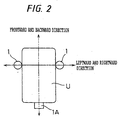
- the above-mentioned vibration isolators 1 are arranged such that the devices 1 face each other in an opposed manner at left and right sides of a power unit U comprised of an engine, a transmission and the like and support the power unit U.
- the vibration isolator 1 is mounted on a support member such as a car-body-side bracket or the like by means of mounting bolts 31 which are protruded downwardly from the lower metal fitting 3.
- a mounting surface 3a of the above-mentioned metal fitting 3 is mounted on a support member B2 such that a given inclination angle ⁇ is made between the mounting surface 3a and a horizontal plane.
- the steering stability and the riding comfort are generally determined by the dynamic spring constants in respective directions consisting of an upward and downward direction of a vehicle and a leftward and rightward direction of the vehicle which the vibration prevention body 4 of the above-mentioned vibration isolator 1 made of the rubber-like elastic body holds. Further, the damping at the time of idling and at the time of runninng is achieved through a liquid filling effect derived from two liquid chambers 5a, 5b, the orifice passage 8 and the like.
- the orifice passage which makes both liquid chambers communicate with each other is generally set to perform the vibration absorption (damping) effect to the shake vibration at the time of the steady-state runninng in the frequency band of 12 to 15 Hz. Accordingly, conventional liquid-filled type vibration isolator exhibits the poor damping effect at the time of idling.
- the present invention provides a liquid-filled type vibration isolator which supports a power unit such as an automobile engine or the like, wherein the liquid-filled type vibration isolator achieves the suppression of vibration and the enhancement of the steering stability and the riding comfort at the time of steady-state runninng by making use of an angle in a vehicle mounted state and a ratio between a dynamic spring constant in the vehicle upward-and-downward direction and a dynamic spring constant in the vehicle leftward-and-rightward direction which are held by a vibration prevention base body made of a rubber-like elastic body, and the liquid-filled type vibration prevention the device achieves the suppression of vibration at the time of idling by making use of a throttling effect of an orifice passage which is formed in a partition member, whereby the liquid-filled type vibration isolator can effectively suppress the vibrations of respectively different vehicles.
- the present invention is directed to a liquid-filled type vibration isolator which includes, in the same manner as the above-mentioned liquid-filled type vibration isolator, two upper and lower metal fittings which are disposed at a vibration body side and a support side, a vibration prevention base body made of a rubber-like elastic body which is interposed between both metal fittings, a diaphragm which is disposed such that the diaphragm faces the vibration prevention base body in an opposed manner, a liquid chamber which is defined between the vibration prevention base body and the diaphragm, and a partition body which partitions this liquid chamber into a main liquid chamber and a sub liquid chamber, and forms an orifice which makes both liquid chambers communicate with each other in a peripheral portion of the partition body, wherein an inclination angle ⁇ which a mounting surface of the lower metal fitting facing a support member of a car body side makes to a horizontal plane is set to not less than 30°, and a ratio (Kd1/Kd2) between a dynamic spring constant (
- the dynamic spring constants can be decreased and advantageous effects related with the improvement of the steering stability and the riding comfort can be greatly enhanced.
- the vibration prevention base body becomes relatively rigid in the upward and downward direction and the dynamic spring constant in the leftward and rightward direction becomes large whereby the power unit is liable to easily wobble in the left and right direction and hence becomes unstable. Accordingly, to ensure the suppression of the vibration at the time of runninng and the improvement of the steering stability and the riding comfort, it is preferable to set the dynamic spring constant ratio within the above-mentioned range.
- the vibration isolator of the present invention the vehicle vibration which differs between the condition at the time of runninng and the condition at the time of idling can be effectively suppressed and the performance of the vehicle can be enhanced.
- the vibration frequency at the time of idling is changed corresponding to the number of cylinders of an engine. For example, when the number of cylinders is 4, the vibration frequency becomes 22-23 Hz, when the number of cylinders is 6, the vibration frequency becomes approximately 30 Hz, and when the number of cylinders is 8, the vibration frequency is around 40 Hz. Accordingly, the cross-sectional area and the length of the orifice passage are determined such that the liquid level resonance action takes place in these vibration frequency bands.
- the vibration frequency band is used in a mode that the band is shifted such that the anti-resonance action derived from the orifice passage does not take place and hence, it is preferable to make the orifice passage perform the vibration attenuation function in the frequency band of the idling vibration in a slightly wide range of 20-60 Hz.
- the reason that the inclination angle ⁇ which the mounting surface of the lower metal fitting facing the support member of the car body side makes to the horizontal plane is set to not less than 30° is to decrease the dynamic spring constant at the time of runninng by setting the ratio (Kd1/Kd2) between the dynamic spring constant of the vibration prevention base body in the upward and downward direction of the vehicle and the dynamic spring constant of the vibration prevention base body in the leftward and rightward direction of the vehicle within the range of 1.0 - 3.0 thereby obtaining advantageous effects with respect to the improvement of the steering stability and the riding comfort.
- the inclination angle ⁇ which the mounting surface of the lower metal fitting facing the supporting member of the car body side makes to the horizontal plane is set to 30° - 50°.
- the power unit which constitutes a supporting object is liable to easily move in the upward and downward direction and hence becomes unstable, while when the inclination angle ⁇ exceeds 50°, the power unit is liable to easily wobble in the left and right direction and hence becomes unstable.
- Fig. 1 shows an example of a liquid-filled type vibration isolator 1 which carries out the present invention.
- the fundamental constitution includes, as mentioned in the Background of the Invention, an upper metal fitting 2 which is mounted on a member B1 which is connected to a power unit such as an engine or the like which constitutes a vibration source side, a lower metal fitting 3 which is mounted on a support member B2 of a car body side, a vibration prevention base body 4 made of a rubber-like elastic body which connects both metal fittings 2, 3 to each other, a diaphragm 6 which is arranged at the metal fitting 3 side while facing the vibration prevention base body 4 in an opposed manner, a liquid chamber 5 which is formed between the vibration prevention base body 4 and the diaphragm 6, and a partition body 7 which partitions the liquid chamber 5 into a main liquid chamber 5a and a sub liquid chamber 5b, and an orifice passage 8 which is formed in an outer peripheral portion of the partition body 7 to make the main liquid chamber 5a and the sub liquid chamber 5b
- the vibration prevention base body 4 has an approximately conical-frustum shape, wherein the upper side metal fitting 2 is fixedly secured to an upper end portion of a small-diameter side thereof by means of vulcanization adhesion means and a cylindrical member 9 which is joined to the lower metal fitting 3 is fixedly secured to a lower large-diameter-side outer peripheral portion thereof by means of vulcanization adhesion means.
- the upper metal fitting 2 has an approximately disc-like shape and a mounting bolt 21 which is fixedly secured by means of press fit means or welding means is protruded upwardly from a central portion of the metal fitting 2.
- the upper metal fitting 2 is fixedly secured to a power-unit- side member B1 of an automobile by means of a mounting bolt 21.
- Numeral 12 indicates a stopper fitting which is called a stabilizer and is integrally secured to the metal fitting 2.
- the stopper fitting 12 is provided for restricting a large displacement of the vibration prevention base body 4 in the upward and downward direction between the stopper fitting 12 and a stopper rubber portion 41 which is formed such that the stopper rubber portion 41 is outwardly protruded from a portion of the vibration prevention base body 4.
- the lower metal fitting 3 has an approximately cylindrical shape with a bottom and a lower end portion of the cylindrical member 9 is fixedly secured to a flange-like open peripheral portion of the metal fitting 3 by means of caulking means.
- An outer peripheral portion of the partition body 7 and an outer peripheral portion of the diaphragm 6 are both fixedly secured to the open peripheral portion of the metal fitting 3.
- a mounting bolt 31 is mounted on a bottom wall portion of the lower metal fitting 3 with the use of press fit means or the like such that the mounting bolt 31 is protruded downwardly in the axial direction of the device.
- the lower metal fitting 3 is fixedly secured to the car-body-side support member B2 by means of this mounting bolt 31.
- An air chamber 10 is defined between the metal fitting 3 and the diaphragm 6. This air chamber is communicated with atmosphere in one case and is formed of an airtight chamber in other case.
- the above-mentioned liquid-filled type vibration isolators 1 are installed _to support the power unit U in a manner that the vibration of the power unit U can be prevented, wherein two liquid-filled isolators 1 are arranged at left and right sides of the power unit U such as an engine or the like mounted on the vehicle in the state that two liquid-filled isolators 1 face each other in an opposed manner.
- the mounting bolts 31 which are protruded from the lower metal fittings 3 of the liquid-filled type vibration isolators 1 are designed to be fastened to the support member B2 such as car-body-side brackets or the like at both left and right sides of the unit U in the state that the mounting bolts 31 are inclined to the upward and downward direction (vertical direction). That is, a support surface of the above-mentioned member B2 makes an inclination angle ⁇ to a horizontal surface which corresponds to the above-mentioned inclination angle and a mounting surface 3a formed of a bottom wall of the lower metal fitting 3 which is mounted on the support surface also makes an inclination of the same angle ⁇ .
- the inclination angle ⁇ which the mounting surface 3a of the lower metal fitting 3 makes to the horizontal surface is set to not less than 30°, and preferably to 30°- 50°. Further, to ensure the stability of the supporting state in the upward and the downward direction as well as in the leftward and rightward direction, a ratio (Kd1/Kd2) between a dynamic spring constant (Kd1) in the upward and downward direction of the vehicle and a dynamic spring constant (Kd2) in the leftward and rightward direction of the vehicle which are held by the vibration prevention base body 4 is set within a range of 1.0 - 3.0.
- the orifice passage 8 is determined to perform the vibration attenuation function in conformity with the vibration frequency band at the time of idling which is changed corresponding to the number of cylinders of the engine. That is, the vibration frequency at the time of idling is changed within a range of 22-40 Hz corresponding to the number of cylinders of an engine having, for example 4 cylinders, 6 cylinders, 8 cylinders or the like. Further, there may be a case that the vibration isolator 1 is served in such a manner that the vibration frequency is shifted to prevent the generation of the anti-resonance action derived from the orifice passage.
- the cross-sectional area and the length of the orifice passage 8 are determined such that the vibration attenuation function derived from the throttling effect and the liquid level resonant action can be performed in the frequency band of the idling vibration with a slightly broad range of 20 - 60 Hz,.
- a vibration isolator 1A having a stopper function in the frontward and backward direction is mounted on a rear end portion of the power unit U.
- the vibration isolators 1 by mounting the vibration isolators 1 such that the inclination angle ⁇ in the mounting state is set to not less than 30° and by setting the ratio (Kd1/Kd2) between the dynamic spring constant of the vibration prevention base body in the upward and downward direction of the vehicle and the dynamic spring constant of the vibration prevention base body in the leftward and rightward direction of the vehicle within the range of 1.0 - 3.0, the dynamic spring constant can be decreased and the steering stability and the riding comfort can be improved.
- the vibration isolators 1 can effectively suppress the vehicle vibration which differs between the condition at the time of the normal runninng and the condition at the time of idling so that the vehicle performance can be enhanced.
- Fig. 3 shows a comparison of the dynamic spring constant in the upward and downward direction and the attenuation coefficient with respect to the liquid-filled type vibration isolator having the structure shown in Fig. 1 and constituting the embodiment in which the inclination angle ⁇ of the mounting surface in the vehicle mounted state is set to 30° and the orifice is set to perform the vibration attenuation function in a given frequency band of the idling vibration and a vibration device having the same identical structure and constituting a comparison example in which the inclination angle ⁇ of the mounting surface in the vehicle mounted state is set to 15° and the orifice is set to perform the vibration attenuation function in the frequency band (12-15 Hz) of the shake vibration.
- the peak frequency of the attenuation coefficient appears around 10 Hz and the dynamic spring constant in the upward and downward direction is increased at the high frequency side in the vicinity of the peak frequency.
- the peak frequency of the attenuation coefficient appears around approximately 44 Hz and the low dynamic spring constant is maintained up to this vicinity and particularly the dynamic spring constant in the vicinity of the frequency 12-15 Hz of the shake vibration is decreased.
- the embodiment can improve the dynamic constant ratio (Kd1/Kd2) at the frequency of 15 Hz, for example in a following manner compared with the dynamic constant ratio of the comparison example.
- the low dynamic constant can be realized and hence, the favorable vibration suppression effect can be achieved and the steering stability and the riding comfort can be enhanced.
- the structure of the liquid-filled type vibration isolator 1, the manner of mounting of the device 1 to the vehicle, the stopper mechanism and the like shown in Fig. 1 merely show one example.
- a liquid-filled type vibration isolator which has other structure but shares the basic constitution in common, the inclination angle of the mounting surface, the ratio between the dynamic spring constant in the upward and downward direction and the dynamic spring constant in the left ward and right ward direction, and the characteristics of the orifice passage can be set and carried out in the same manner as mentioned above.
- the liquid-filled type vibration isolator with respect to the suppression of the vibration and the improvement of the steering stability and the riding comfort at the time of runninng, they can be achieved by determining the inclination angle of the mounting surface in the vehicle mounted state and the ratio between the dynamic spring constant of the vibration prevention body made of the rubber-like elastic body in the upward and downward direction of the vehicle and the dynamic spring constant of the vibration prevention body in the leftward and rightward direction of the vehicle, while with respect to the suppression of vibration at the time of idling, it can be achieved by the throttling effect of the orifice passage which is formed in the partition member so that the vibrations of vehicles which are different from each other can be effectively suppressed and hence, the vehicle characteristics can be enhanced.
Landscapes
- Engineering & Computer Science (AREA)
- General Engineering & Computer Science (AREA)
- Mechanical Engineering (AREA)
- Arrangement Or Mounting Of Propulsion Units For Vehicles (AREA)
- Combined Devices Of Dampers And Springs (AREA)
Abstract
The present invention provides a liquid-filled type vibration isolator which supports a power unit such as an automobile engine or the like which can effectively perform the suppression of the vibration and the improvement of the steering stability and the riding comfort at the time of runninng and the suppression of vibration at the time of idling. To achieve such advantages, the liquid-filled type vibration isolator comprises a vibration prevention base body (4) made of a rubber-like elastic body which is interposed between upper and lower metal fittings (2)(3), a liquid chamber (5) which is defined between the vibration prevention base body (4) and a diaphragm (6), a partition body (7) which partitions the liquid chamber into two chambers and an orifice passage (8), wherein an inclination angle (θ) which a mounting surface (3a) of the lower metal fitting (3) facing a support member (B) of a car body side makes to a horizontal plane is set to not less than 30 DEG , and a ratio (Kd1/Kd2) between a dynamic spring constant (Kd1) in the upward and downward direction of a vehicle and a dynamic spring constant (Kd2) in the leftward and rightward direction of the vehicle which are held by the vibration prevention base body (4) is set within a range of 1.0-3.0, and the orifice is set such that the orifice is capable of performing the vibration attenuation function in a vibration frequency band at the time of idling. <IMAGE>
Description
The present invention mainly relates to a liquid-filled
type vibration isolator which is used for supporting a power
unit of an automobile engine or the like while preventing the
vibration.
As a mount which supports a power unit such as an
automobile engine while preventing the transmission of
vibration of the power unit to a car body side, a liquid-filled
type vibration isolator shown in Fig. 1 is known, for example.
Such a liquid-filled type vibration isolator 1 includes
an upper metal fitting 2 which is mounted on a vibration source
side, a lower metal fitting 3 which is mounted on a car body
side, a vibration prevention base body 4 made of a rubber-like
elastic body which connects both metal fittings 2, 3 to each
other, a diaphragm 6 which is arranged at the metal fitting 3
side while facing the vibration prevention base body 4 in an
opposed manner, a liquid chamber 5 which is formed between the
vibration prevention base body 4 and the diaphragm 6, a
partition body 7 which partitions the liquid chamber 5 into a
main liquid chamber 5a and a sub liquid chamber 5b, and an orifice
passage 8 which is formed in an outer peripheral portion or the
like of the partition body 7 to make the main liquid chamber
5a and the sub liquid chamber 5b communicate with each other.
Due to the liquid level resonance action generated by the liquid
flows in both liquid chambers through the orifice passage 8 and
the vibration absorption effect derived from the resiliency of
the vibration prevention body, the liquid-filled type vibration
isolator can perform the vibration attenuation function and the
vibration insulation function.
Usually, as shown in Fig. 2, the above-mentioned
vibration isolators 1 are arranged such that the devices 1 face
each other in an opposed manner at left and right sides of a
power unit U comprised of an engine, a transmission and the like
and support the power unit U. The vibration isolator 1 is
mounted on a support member such as a car-body-side bracket or
the like by means of mounting bolts 31 which are protruded
downwardly from the lower metal fitting 3. In this case, as
shown in Fig. 1, it is often the case that a mounting surface
3a of the above-mentioned metal fitting 3 is mounted on a support
member B2 such that a given inclination angle is made between
the mounting surface 3a and a horizontal plane.
In the above-mentioned support structure for the power
unit U, the steering stability and the riding comfort are
generally determined by the dynamic spring constants in
respective directions consisting of an upward and downward
direction of a vehicle and a leftward and rightward direction
of the vehicle which the vibration prevention body 4 of the
above-mentioned vibration isolator 1 made of the rubber-like
elastic body holds. Further, the damping at the time of idling
and at the time of runninng is achieved through a liquid filling
effect derived from two liquid chambers 5a, 5b, the orifice
passage 8 and the like.
Here, in case of this type of conventional liquid-filled
type vibration isolator, the orifice passage which makes both
liquid chambers communicate with each other is generally set
to perform the vibration absorption (damping) effect to the
shake vibration at the time of the steady-state runninng in the
frequency band of 12 to 15 Hz. Accordingly, conventional
liquid-filled type vibration isolator exhibits the poor damping
effect at the time of idling.
Further, there has been a case that, depending on the
inclination angle in the mounting state of vibration
prevention base body 4 to the car-body-side bracket of the
vehicle when the vibration prevention base body 4 is mounted
on the vehicle, the dynamic spring constants in the vehicle
upward-and-downward direction and in the vehicle leftward-and-rightward
direction held by the vibration prevention base
body 4 are not sufficient to suppress the vibration and to
enhance the steering stability and the riding comfort.
The present invention provides a liquid-filled type
vibration isolator which supports a power unit such as an
automobile engine or the like, wherein the liquid-filled type
vibration isolator achieves the suppression of vibration and
the enhancement of the steering stability and the riding comfort
at the time of steady-state runninng by making use of an angle
in a vehicle mounted state and a ratio between a dynamic spring
constant in the vehicle upward-and-downward direction and a
dynamic spring constant in the vehicle leftward-and-rightward
direction which are held by a vibration prevention base body
made of a rubber-like elastic body, and the liquid-filled type
vibration prevention the device achieves the suppression of
vibration at the time of idling by making use of a throttling
effect of an orifice passage which is formed in a partition
member, whereby the liquid-filled type vibration isolator can
effectively suppress the vibrations of respectively different
vehicles.
The present invention is directed to a liquid-filled type
vibration isolator which includes, in the same manner as the
above-mentioned liquid-filled type vibration isolator, two
upper and lower metal fittings which are disposed at a vibration
body side and a support side, a vibration prevention base body
made of a rubber-like elastic body which is interposed between
both metal fittings, a diaphragm which is disposed such that
the diaphragm faces the vibration prevention base body in an
opposed manner, a liquid chamber which is defined between the
vibration prevention base body and the diaphragm, and a
partition body which partitions this liquid chamber into a main
liquid chamber and a sub liquid chamber, and forms an orifice
which makes both liquid chambers communicate with each other
in a peripheral portion of the partition body, wherein an
inclination angle which a mounting surface of the lower metal
fitting facing a support member of a car body side makes to a
horizontal plane is set to not less than 30°, and a ratio
(Kd1/Kd2) between a dynamic spring constant (Kd1) in the upward
and downward direction of a vehicle and a dynamic spring
constant (Kd2) in the leftward and rightward direction of the
vehicle which are held by the vibration prevention base body
is set within a range of 1.0-3.0, and the orifice is set such
that the orifice is capable of performing the vibration
attenuation function in a vibration frequency band at the time
of idling.
According to this liquid-filled type vibration isolator,
at the time of runninng of the vehicle, due to the elastic
deformation of the vibration prevention base body made of the
rubber-like elastic body which sets the ratio between the
dynamic spring constant in the upward and downward direction
of the vehicle and the dynamic spring constant in the leftward
and rightward direction of the vehicle in the above-mentioned
manner, a favorable vibration prevention effect can be achieved.
Particularly, by mounting the liquid-filled type vibration
isolator with the inclination angle in the mounting state set
to not less than 30° and by setting the ratio (Kd1/Kd2) between
the dynamic spring constant of the vibration prevention base
body in the upward and downward direction of the vehicle and
the dynamic spring constant of the vibration prevention base
body in the leftward and rightward direction of the vehicle
within the range of 1.0 - 3.0, the dynamic spring constants can
be decreased and advantageous effects related with the
improvement of the steering stability and the riding comfort
can be greatly enhanced.
That is, since the static spring constant (Ks) in the
upward and the downward direction is fixed, when the ratio
(Kd1/Kd2) between the dynamic spring constant in the upward and
downward direction of the vehicle and the dynamic spring
constant in the leftward and rightward direction of the vehicle
exceeds 3.0, the dynamic spring constant in the upward and
downward direction of the vehicle becomes greater than the
dynamic spring constant in the leftward and rightward direction
of the vehicle so that the power unit which constitutes a
supporting object is liable to be easily moved in the upward
and downward direction and hence, becomes unstable. Further,
when the dynamic constant ratio (Kd1/Kd2) is less than 1.0, the
vibration prevention base body becomes relatively rigid in the
upward and downward direction and the dynamic spring constant
in the leftward and rightward direction becomes large whereby
the power unit is liable to easily wobble in the left and right
direction and hence becomes unstable. Accordingly, to ensure
the suppression of the vibration at the time of runninng and
the improvement of the steering stability and the riding comfort,
it is preferable to set the dynamic spring constant ratio within
the above-mentioned range.
Further, at the time of idling, due to a throttling effect
of the orifice passage which is formed so as to perform the
vibration attenuation function in the vibration frequency band
of the idling vibration, a favorable vibration suppression
effect can be achieved.
Accordingly, with the vibration isolator of the present
invention, the vehicle vibration which differs between the
condition at the time of runninng and the condition at the time
of idling can be effectively suppressed and the performance of
the vehicle can be enhanced.
The vibration frequency at the time of idling is changed
corresponding to the number of cylinders of an engine. For
example, when the number of cylinders is 4, the vibration
frequency becomes 22-23 Hz, when the number of cylinders is 6,
the vibration frequency becomes approximately 30 Hz, and when
the number of cylinders is 8, the vibration frequency is around
40 Hz. Accordingly, the cross-sectional area and the length
of the orifice passage are determined such that the liquid level
resonance action takes place in these vibration frequency bands.
However, there may be a case that the vibration frequency band
is used in a mode that the band is shifted such that the
anti-resonance action derived from the orifice passage does not
take place and hence, it is preferable to make the orifice
passage perform the vibration attenuation function in the
frequency band of the idling vibration in a slightly wide range
of 20-60 Hz.
In the above-mentioned liquid-filled type vibration
isolator, the reason that the inclination angle which the
mounting surface of the lower metal fitting facing the support
member of the car body side makes to the horizontal plane is
set to not less than 30° is to decrease the dynamic spring
constant at the time of runninng by setting the ratio (Kd1/Kd2)
between the dynamic spring constant of the vibration prevention
base body in the upward and downward direction of the vehicle
and the dynamic spring constant of the vibration prevention base
body in the leftward and rightward direction of the vehicle
within the range of 1.0 - 3.0 thereby obtaining advantageous
effects with respect to the improvement of the steering
stability and the riding comfort.
Further, for this end, it is preferable to set the
inclination angle which the mounting surface of the lower metal
fitting facing the supporting member of the car body side makes
to the horizontal plane to 30° - 50°.
That is, when the inclination angle is not more than
30°, the power unit which constitutes a supporting object is
liable to easily move in the upward and downward direction and
hence becomes unstable, while when the inclination angle
exceeds 50°, the power unit is liable to easily wobble in the
left and right direction and hence becomes unstable.
A preferred embodiment of a liquid-filled type vibration
isolator of the present invention is explained in conjunction
with drawings hereinafter. However, the present invention is
not limited to such an embodiment.
Fig. 1 shows an example of a liquid-filled type vibration
isolator 1 which carries out the present invention. The
fundamental constitution includes, as mentioned in the
Background of the Invention, an upper metal fitting 2 which is
mounted on a member B1 which is connected to a power unit such
as an engine or the like which constitutes a vibration source
side, a lower metal fitting 3 which is mounted on a support member
B2 of a car body side, a vibration prevention base body 4 made
of a rubber-like elastic body which connects both metal fittings
2, 3 to each other, a diaphragm 6 which is arranged at the metal
fitting 3 side while facing the vibration prevention base body
4 in an opposed manner, a liquid chamber 5 which is formed between
the vibration prevention base body 4 and the diaphragm 6, and
a partition body 7 which partitions the liquid chamber 5 into
a main liquid chamber 5a and a sub liquid chamber 5b, and an
orifice passage 8 which is formed in an outer peripheral portion
of the partition body 7 to make the main liquid chamber 5a and
the sub liquid chamber 5b communicate with each other.
In the drawing, the vibration prevention base body 4 has
an approximately conical-frustum shape, wherein the upper side
metal fitting 2 is fixedly secured to an upper end portion of
a small-diameter side thereof by means of vulcanization
adhesion means and a cylindrical member 9 which is joined to
the lower metal fitting 3 is fixedly secured to a lower
large-diameter-side outer peripheral portion thereof by means
of vulcanization adhesion means.
The upper metal fitting 2 has an approximately disc-like
shape and a mounting bolt 21 which is fixedly secured by means
of press fit means or welding means is protruded upwardly from
a central portion of the metal fitting 2. The upper metal
fitting 2 is fixedly secured to a power-unit- side member B1
of an automobile by means of a mounting bolt 21. Numeral 12
indicates a stopper fitting which is called a stabilizer and
is integrally secured to the metal fitting 2. The stopper
fitting 12 is provided for restricting a large displacement of
the vibration prevention base body 4 in the upward and downward
direction between the stopper fitting 12 and a stopper rubber
portion 41 which is formed such that the stopper rubber portion
41 is outwardly protruded from a portion of the vibration
prevention base body 4.
The lower metal fitting 3 has an approximately
cylindrical shape with a bottom and a lower end portion of the
cylindrical member 9 is fixedly secured to a flange-like open
peripheral portion of the metal fitting 3 by means of caulking
means. An outer peripheral portion of the partition body 7 and
an outer peripheral portion of the diaphragm 6 are both fixedly
secured to the open peripheral portion of the metal fitting 3.
Further, a mounting bolt 31 is mounted on a bottom wall portion
of the lower metal fitting 3 with the use of press fit means
or the like such that the mounting bolt 31 is protruded
downwardly in the axial direction of the device. The lower
metal fitting 3 is fixedly secured to the car-body-side support
member B2 by means of this mounting bolt 31. An air chamber
10 is defined between the metal fitting 3 and the diaphragm 6.
This air chamber is communicated with atmosphere in one case
and is formed of an airtight chamber in other case.
In an engine room of the automobile, as shown in Fig. 2,
the above-mentioned liquid-filled type vibration isolators 1
are installed _to support the power unit U in a manner that the
vibration of the power unit U can be prevented, wherein two
liquid-filled isolators 1 are arranged at left and right sides
of the power unit U such as an engine or the like mounted on
the vehicle in the state that two liquid-filled isolators 1 face
each other in an opposed manner.
Here, the mounting bolts 31 which are protruded from the
lower metal fittings 3 of the liquid-filled type vibration
isolators 1 are designed to be fastened to the support member
B2 such as car-body-side brackets or the like at both left and
right sides of the unit U in the state that the mounting bolts
31 are inclined to the upward and downward direction (vertical
direction). That is, a support surface of the above-mentioned
member B2 makes an inclination angle to a horizontal surface
which corresponds to the above-mentioned inclination angle and
a mounting surface 3a formed of a bottom wall of the lower metal
fitting 3 which is mounted on the support surface also makes
an inclination of the same angle .
In this invention, the inclination angle which the
mounting surface 3a of the lower metal fitting 3 makes to the
horizontal surface is set to not less than 30°, and preferably
to 30°- 50°. Further, to ensure the stability of the supporting
state in the upward and the downward direction as well as in
the leftward and rightward direction, a ratio (Kd1/Kd2) between
a dynamic spring constant (Kd1) in the upward and downward
direction of the vehicle and a dynamic spring constant (Kd2)
in the leftward and rightward direction of the vehicle which
are held by the vibration prevention base body 4 is set within
a range of 1.0 - 3.0.
Further, with respect to the orifice passage 8 formed in
the outer peripheral portion of the above-mentioned partition
body 7, the orifice passage 8 is determined to perform the
vibration attenuation function in conformity with the vibration
frequency band at the time of idling which is changed
corresponding to the number of cylinders of the engine. That
is, the vibration frequency at the time of idling is changed
within a range of 22-40 Hz corresponding to the number of
cylinders of an engine having, for example 4 cylinders, 6
cylinders, 8 cylinders or the like. Further, there may be a
case that the vibration isolator 1 is served in such a manner
that the vibration frequency is shifted to prevent the
generation of the anti-resonance action derived from the
orifice passage. Accordingly, the cross-sectional area and
the length of the orifice passage 8 are determined such that
the vibration attenuation function derived from the throttling
effect and the liquid level resonant action can be performed
in the frequency band of the idling vibration with a slightly
broad range of 20 - 60 Hz,.
Here, apart from the above-mentioned vibration isolators
1, a vibration isolator 1A having a stopper function in the
frontward and backward direction is mounted on a rear end
portion of the power unit U.
In the above-mentioned support structure, at the time of
runninng of the vehicle, due to the elastic deformation of the
vibration prevention base body 4 which sets the ratio between
the dynamic spring constant in the upward and downward direction
of the vehicle and the dynamic spring constant in the left
ward and right ward direction of the vehicle within the
above-mentioned specified range, a favorable vibration
suppression effect can be achieved. Particularly, by mounting
the vibration isolators 1 such that the inclination angle in
the mounting state is set to not less than 30° and by setting
the ratio (Kd1/Kd2) between the dynamic spring constant of the
vibration prevention base body in the upward and downward
direction of the vehicle and the dynamic spring constant of the
vibration prevention base body in the leftward and rightward
direction of the vehicle within the range of 1.0 - 3.0, the
dynamic spring constant can be decreased and the steering
stability and the riding comfort can be improved.
Further, at the time of idling, due to the throttling
effect of the orifice passage which is formed such that the
vibration attenuation function is performed in the vibration
frequency band of the idling vibration, the advantageous effect
of favorably suppressing the vibration can be achieved.
Accordingly, the vibration isolators 1 can effectively suppress
the vehicle vibration which differs between the condition at
the time of the normal runninng and the condition at the time
of idling so that the vehicle performance can be enhanced.
Fig. 3 shows a comparison of the dynamic spring constant
in the upward and downward direction and the attenuation
coefficient with respect to the liquid-filled type vibration
isolator having the structure shown in Fig. 1 and constituting
the embodiment in which the inclination angle of the mounting
surface in the vehicle mounted state is set to 30° and the orifice
is set to perform the vibration attenuation function in a given
frequency band of the idling vibration and a vibration device
having the same identical structure and constituting a
comparison example in which the inclination angle of the
mounting surface in the vehicle mounted state is set to 15° and
the orifice is set to perform the vibration attenuation function
in the frequency band (12-15 Hz) of the shake vibration.
According to this Fig. 3, in the case of the comparison
example, the peak frequency of the attenuation coefficient
appears around 10 Hz and the dynamic spring constant in the
upward and downward direction is increased at the high frequency
side in the vicinity of the peak frequency. To the contrary,
in the embodiment, the peak frequency of the attenuation
coefficient appears around approximately 44 Hz and the low
dynamic spring constant is maintained up to this vicinity and
particularly the dynamic spring constant in the vicinity of the
frequency 12-15 Hz of the shake vibration is decreased.
Accordingly, along with the fact that while the
inclination angle in the vehicle mounted state is set to 15°
in the comparison example, the inclination angle in the vehicle
mounted state is set to 30° in the embodiment, the embodiment
can improve the dynamic constant ratio (Kd1/Kd2) at the
frequency of 15 Hz, for example in a following manner compared
with the dynamic constant ratio of the comparison example.
Kd1/Kd2 = 695/200 = 3.48 (comparison example)
Kd1/Kd2 = 295/193 = 1.53 (embodiment)
Accordingly, at the time of usual runninng, the low
dynamic constant can be realized and hence, the favorable
vibration suppression effect can be achieved and the steering
stability and the riding comfort can be enhanced.
The structure of the liquid-filled type vibration
isolator 1, the manner of mounting of the device 1 to the vehicle,
the stopper mechanism and the like shown in Fig. 1 merely show
one example. With respect to a liquid-filled type vibration
isolator which has other structure but shares the basic
constitution in common, the inclination angle of the mounting
surface, the ratio between the dynamic spring constant in the
upward and downward direction and the dynamic spring constant
in the left ward and right ward direction, and the
characteristics of the orifice passage can be set and carried
out in the same manner as mentioned above.
As has been described above, according to the liquid-filled
type vibration isolator, with respect to the suppression
of the vibration and the improvement of the steering stability
and the riding comfort at the time of runninng, they can be
achieved by determining the inclination angle of the mounting
surface in the vehicle mounted state and the ratio between the
dynamic spring constant of the vibration prevention body made
of the rubber-like elastic body in the upward and downward
direction of the vehicle and the dynamic spring constant of the
vibration prevention body in the leftward and rightward
direction of the vehicle, while with respect to the suppression
of vibration at the time of idling, it can be achieved by the
throttling effect of the orifice passage which is formed in the
partition member so that the vibrations of vehicles which are
different from each other can be effectively suppressed and
hence, the vehicle characteristics can be enhanced.
Claims (3)
- A liquid-filled type vibration isolator comprising two upper and lower metal fittings which is disposed at a vibration body side and a support side, a vibration prevention base body made of a rubber-like elastic body which is interposed between both metal fittings, a diaphragm which is disposed such that the diaphragm faces the vibration prevention base body in an opposed manner, a liquid chamber which is defined between the vibration prevention base body and the diaphragm, and a partition body which partitions this liquid chamber into a main liquid chamber and a sub liquid chamber and, forming an orifice which makes both liquid chambers communicate with each other in a peripheral portion of the partition body, wherein
an inclination angle which a mounting surface of the lower metal fitting which faces a support member of a car body side makes to a horizontal plane is set to not less than 30°, and
a ratio (Kd1/Kd2) between a dynamic spring constant (Kd1) in the upward and downward direction of a vehicle and a dynamic spring constant (Kd2) in the leftward and rightward direction of the vehicle which are held by the vibration prevention base body is set within a range of 1.0 - 3.0, and the orifice is set such that the orifice is capable of performing the vibration attenuation function in a vibration frequency band at the time of idling. - A liquid-filled type vibration isolator according to claim 1, wherein the inclination angle which the mounting surface of the lower metal fitting which faces the support member of the car body side makes to the horizontal plane is set to 30° - 50°.
- A liquid-filled type vibration isolator according to claim 1 or 2, wherein said orifice is set to perform the vibration attenuation function in the frequency band of the idling vibration of 20 - 60 Hz.
Applications Claiming Priority (1)
| Application Number | Priority Date | Filing Date | Title |
|---|---|---|---|
| PCT/JP2001/000008 WO2002055900A1 (en) | 2001-01-04 | 2001-01-04 | Liquid-filled vibration isolator |
Publications (1)
| Publication Number | Publication Date |
|---|---|
| EP1262682A1 true EP1262682A1 (en) | 2002-12-04 |
Family
ID=11736876
Family Applications (1)
| Application Number | Title | Priority Date | Filing Date |
|---|---|---|---|
| EP01900252A Withdrawn EP1262682A1 (en) | 2001-01-04 | 2001-01-04 | Liquid-filled vibration isolator |
Country Status (3)
| Country | Link |
|---|---|
| EP (1) | EP1262682A1 (en) |
| JP (1) | JP3587194B2 (en) |
| WO (1) | WO2002055900A1 (en) |
Cited By (1)
| Publication number | Priority date | Publication date | Assignee | Title |
|---|---|---|---|---|
| EP1433640A1 (en) * | 2002-12-25 | 2004-06-30 | Carl Freudenberg KG | Support structure for transversal engine |
Families Citing this family (2)
| Publication number | Priority date | Publication date | Assignee | Title |
|---|---|---|---|---|
| JP6172703B2 (en) * | 2012-12-21 | 2017-08-02 | 東洋ゴム工業株式会社 | Power plant support structure |
| JP2020045021A (en) * | 2018-09-20 | 2020-03-26 | いすゞ自動車株式会社 | Engine mount structure |
Family Cites Families (5)
| Publication number | Priority date | Publication date | Assignee | Title |
|---|---|---|---|---|
| JP2520276Y2 (en) * | 1989-10-02 | 1996-12-11 | 北辰工業 株式会社 | Liquid-filled anti-vibration mount |
| JP2827580B2 (en) * | 1991-06-17 | 1998-11-25 | トヨタ自動車株式会社 | Liquid filled vibration isolator |
| JPH0533825A (en) * | 1991-07-29 | 1993-02-09 | Tokai Rubber Ind Ltd | Anti-vibration support |
| DE4205229C2 (en) * | 1992-02-21 | 1994-02-24 | Boge Gmbh | Hydraulically damping rubber bearing |
| US5772189A (en) * | 1995-06-15 | 1998-06-30 | Yamashita Rubber Kabuskiki Kaisha | Antivibration rubber device |
-
2001
- 2001-01-04 JP JP2001562918A patent/JP3587194B2/en not_active Expired - Fee Related
- 2001-01-04 EP EP01900252A patent/EP1262682A1/en not_active Withdrawn
- 2001-01-04 WO PCT/JP2001/000008 patent/WO2002055900A1/en not_active Ceased
Non-Patent Citations (1)
| Title |
|---|
| See references of WO02055900A1 * |
Cited By (2)
| Publication number | Priority date | Publication date | Assignee | Title |
|---|---|---|---|---|
| EP1433640A1 (en) * | 2002-12-25 | 2004-06-30 | Carl Freudenberg KG | Support structure for transversal engine |
| CN1328080C (en) * | 2002-12-25 | 2007-07-25 | 本田技研工业株式会社 | Supporting structure of transverse engine |
Also Published As
| Publication number | Publication date |
|---|---|
| JPWO2002055900A1 (en) | 2004-05-20 |
| WO2002055900A1 (en) | 2002-07-18 |
| JP3587194B2 (en) | 2004-11-10 |
Similar Documents
| Publication | Publication Date | Title |
|---|---|---|
| US4203499A (en) | Apparatus for preventing or damping vibrations and noise in a vehicle | |
| JP2002227921A (en) | Anti-vibration device | |
| US5035407A (en) | Fluid-filled power unit mount | |
| JP5916502B2 (en) | Anti-vibration support structure | |
| EP1359040B1 (en) | Vehicular power plant mounting system | |
| JPH10238578A (en) | Anti-vibration device | |
| US20030030199A1 (en) | Liquid-filled type vibration isolator | |
| JP3587194B2 (en) | Liquid-filled vibration isolator | |
| EP1410937B1 (en) | Structure for supportting drive device unit | |
| KR102437470B1 (en) | Rear Mounting Structure of Powertrain for Automotive | |
| JP4331919B2 (en) | Vibration isolator | |
| JPH0789356A (en) | Vehicle anti-vibration mount support structure | |
| JPH06307487A (en) | Anti-vibration mount for vehicle | |
| JP3088686B2 (en) | Liquid filled type vibration damping device | |
| JP2002206581A (en) | Anti-vibration rubber device | |
| JP3774812B2 (en) | Liquid filled vibration isolator | |
| JP3072407B2 (en) | Cylindrical liquid-filled anti-vibration mount | |
| JP4227138B2 (en) | Liquid filled vibration isolator | |
| JP3774817B2 (en) | Liquid filled vibration isolator | |
| JPH06330983A (en) | Liquid-sealed type vibration isolating support device | |
| JP3298952B2 (en) | Liquid-filled mounting device | |
| JP2011218901A (en) | Seat back board for vehicle | |
| KR100501433B1 (en) | Engine mounting apparatus | |
| JP2010091042A (en) | Vibration damper | |
| JP2006097717A (en) | Liquid seal type vibration isolator |
Legal Events
| Date | Code | Title | Description |
|---|---|---|---|
| PUAI | Public reference made under article 153(3) epc to a published international application that has entered the european phase |
Free format text: ORIGINAL CODE: 0009012 |
|
| 17P | Request for examination filed |
Effective date: 20020924 |
|
| AK | Designated contracting states |
Kind code of ref document: A1 Designated state(s): DE FR GB |
|
| STAA | Information on the status of an ep patent application or granted ep patent |
Free format text: STATUS: THE APPLICATION HAS BEEN WITHDRAWN |
|
| 18W | Application withdrawn |
Effective date: 20030430 |