EP1262379A2 - Protection device for automobile seat occupant - Google Patents
Protection device for automobile seat occupant Download PDFInfo
- Publication number
- EP1262379A2 EP1262379A2 EP02011517A EP02011517A EP1262379A2 EP 1262379 A2 EP1262379 A2 EP 1262379A2 EP 02011517 A EP02011517 A EP 02011517A EP 02011517 A EP02011517 A EP 02011517A EP 1262379 A2 EP1262379 A2 EP 1262379A2
- Authority
- EP
- European Patent Office
- Prior art keywords
- cover
- glove box
- disposed
- protection device
- seat occupant
- Prior art date
- Legal status (The legal status is an assumption and is not a legal conclusion. Google has not performed a legal analysis and makes no representation as to the accuracy of the status listed.)
- Granted
Links
Images

Classifications
-
- B—PERFORMING OPERATIONS; TRANSPORTING
- B60—VEHICLES IN GENERAL
- B60R—VEHICLES, VEHICLE FITTINGS, OR VEHICLE PARTS, NOT OTHERWISE PROVIDED FOR
- B60R21/00—Arrangements or fittings on vehicles for protecting or preventing injuries to occupants or pedestrians in case of accidents or other traffic risks
- B60R21/02—Occupant safety arrangements or fittings, e.g. crash pads
- B60R21/16—Inflatable occupant restraints or confinements designed to inflate upon impact or impending impact, e.g. air bags
- B60R21/20—Arrangements for storing inflatable members in their non-use or deflated condition; Arrangement or mounting of air bag modules or components
- B60R21/205—Arrangements for storing inflatable members in their non-use or deflated condition; Arrangement or mounting of air bag modules or components in dashboards
Definitions
- the present invention relates to protection devices for automobile seat occupants.
- the present invention relates to a protection device which is used as a leg-protecting device for an automobile seat occupant for protecting the legs of a seat occupant in the case of collision of the automobile, and more specifically, to a protection device for an automobile seat occupant in which an air bag is provided in a glove box.
- protection devices for protecting automobile seat occupants when high-speed moving bodies such as automobiles collide including airbags provided inside interior panels (in spaces formed inside the interior panels), gas generators for inflating the airbags, and covers which cover the airbags in a normal state (when the high-speed moving bodies such as automobiles are not in an emergency state such as a collision).
- the airbag is folded and is disposed inside the interior panel in a normal state.
- the cover is mounted so as to cover the folded body of the airbag.
- the gas generator starts to eject gas, the ejected gas is supplied into the airbag, and the airbag inflates rapidly.
- the cover opens as the airbag inflates, allowing the airbag to expand to the outside of the interior panel and to extend between the interior panel and the seat occupant, thereby protecting the seat occupant.
- Such an airbag-type protection device for a seat occupant includes an airbag disposed in the cover of a glove box for protecting legs of the seat occupant such that the airbag inflates in front of the legs.
- an object of the present invention is to provide a protection device for an automobile seat occupant, being disposed in a glove box, wherein the glove box or the cover thereof can be easily opened and closed.
- a protection device for an automobile seat occupant comprises a glove box having at least a cover rotatable about a supporting shaft and being disposed in front of a seat of an automobile; an air bag disposed in the cover of the glove box; and a gas generator for inflating the air bag.
- the gas generator is disposed on the supporting shaft side of an intermediate portion of the cover in the radial direction of the locus of the free end of the rotatable cover.
- the heavy gas generator is disposed close to the supporting shaft. Therefore, the centroid of the rotatable glove box or the cover thereof is disposed in the vicinity of the supporting shaft, thereby reducing the force required for opening and closing the glove box or the cover thereof.
- a further protection device for an automobile seat occupant comprises a glove box having at least a cover rotatable about a supporting shaft and being disposed in front of a seat of an automobile; an air bag disposed in the cover of the glove box; and a gas generator for inflating the air bag. At least one part of the gas generator is disposed at the opposite side of the cover with respect to the supporting shaft.
- a further protection device for an automobile seat occupant comprises a glove box having at least a cover rotatable about a supporting shaft and being disposed in front of a seat of an automobile; an air bag disposed in the cover of the glove box; and a gas generator for inflating the air bag.
- the cover is provided with a protrusion protruding to the opposite side of the cover with respect to the supporting shaft, and the protrusion includes a balance weight.
- the protection device for an automobile seat occupant comprises a rotatable glove box or a cover thereof of which the centroid is disposed in the vicinity of the supporting shaft. Therefore, the force required for opening and closing the glove box or the cover thereof is reduced.
- the distance between the centroid of the components, which are rotatable about the supporting shaft, and the axis of the supporting shaft is preferably not greater than 100 mm.
- the protection device for an automobile seat occupant can be appropriately used as a leg-protecting device for an automobile seat occupant.
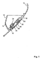
- Fig. 1 is a longitudinal-sectional view of a portion in the vicinity of a glove box of an automobile, the glove box being provided with a leg-protecting device for a seat occupant as a protection device for an automobile seat occupant, according to an embodiment of the present invention.
- a glove box 12 is mounted to an interior panel (for example, an instrument panel or a lower panel) 10 disposed in front of a seat of an automobile.
- the glove box 12 includes a receiving part 14 which is an open-top container, and a cover 16 which forms a front face of the receiving part 14.
- the glove box 12 is rotatably supported by a hinge shaft 18 as a supporting shaft.
- the glove box 12 can be positioned either in a closed state shown in Fig. 1 in which the cover 16 is flush with the interior panel 10, or in an open state in which the receiving part 14 and the cover 16 rotate as a unit toward the right in Fig. 1 about the hinge shaft 18.
- Fig. 2 shows a glove box in an open state, according to another embodiment of the present invention which is described below.
- the glove box 12 is provided with a latch mechanism and a lock mechanism (neither are shown) for latching and locking the glove box 12 when it is closed.
- the airbag device 30 is mounted in the cover 16.
- the airbag device 30 includes a folded airbag 32, an inflator (gas generator) 34 for inflating the airbag 32, and a flap part 38 made of a synthetic resin that is formed integrally with the cover 16.
- the flap part 38 includes two flaps that open outward.
- a tear line 36 extends between the two flaps of the flap part 38.
- a space for receiving the airbag 32 is formed at the rear side of the flap part 38.
- a gas inlet of the airbag 32 is fixed at an edge thereof to the rear face of the cover 16 via a flange of the inflator 34.
- the inflator 34 is disposed on the hinge shaft 18 side of an intermediate portion of the cover 16 in the radial direction of the locus of the free end of the cover which rotates about the hinge shaft 18, that is, an intermediate portion between the axis of the hinge shaft 18 and the end of the cover 16 opposite to the hinge shaft 18 (the end of the cover 16 at the upper right in Fig. 1).
- the whole inflator 34 is preferably disposed on the hinge shaft 18 side of the intermediate portion. However, a part of the inflator 34 may be disposed farther from the hinge shaft 18 than the intermediate portion from the hinge shaft 18 as long as a major part of the inflator 34 is disposed closer to the hinge shaft 18 than the intermediate portion to the hinge shaft 18.
- the inflator 34 which has a larger mass than the airbag 32, is disposed in the vicinity of the hinge shaft 18, the centroid of the glove box 12 is positioned in the vicinity of the hinge shaft 18. Therefore, the force required for opening and closing the glove box 12 can be reduced, and opening and closing of the glove box 12 can be performed easily.
- the inflator 34 ejects a gas to inflate the airbag 32.
- the inflating airbag 32 pushes the flap part 38, and the flap part 38 is thereby broken at the tear line 36 thereof and starts to open.
- the airbag 32 extends along the front face of the glove box 12 and the interior panel 10 disposed around the glove box 12. The legs of the seat occupant are received by the airbag 32 and are thereby protected.
- Fig. 2 is a longitudinal-sectional view showing another embodiment according to the present invention.
- a protrusion 40 protruding from a glove box 12 to the opposite side of a cover 16 with respect to a hinge shaft 18 is formed integrally with the glove box 12, the protrusion 40 being provided at the protruding free end thereof with a balance weight 42.
- the other configuration shown in Fig. 2 is the same as that shown in Fig. 1, in which the same reference numerals are used for referring to the same components.
- Fig. 2 shows the glove box 12 in an open state. The glove box 12 shown in Fig. 2 enters a closed state when it rotates about a hinge shaft 18 such that a cover 16 becomes flush with an interior panel 10.
- the centroid of the glove box 12 is disposed close to the hinge shaft 18, whereby the glove box 12 can be rotated easily for opening and closing with a small force.
- an inflator 34 is disposed on the side of the hinge shaft 18 in the same manner as shown in Fig. 1. Therefore, the centroid of the glove box 12 is disposed closer to the hinge shaft 18 than the case shown in Fig. 1, whereby the glove box 12 can be opened and closed with a smaller force.
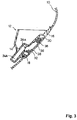
- Fig. 3 is a longitudinal-sectional view of a protection device for an automobile seat occupant, according to still another embodiment of the present invention.
- a cylindrical inflator 34A is used.
- the inflator 34A extends crossing the axis of a hinge shaft 18 (in a direction perpendicular to the axis, according to the present embodiment).
- a gas outlet 34a disposed at an end of the inflator 34A is positioned in a cover 16, whereby gas can be ejected into an airbag 32 through the gas outlet 34a.
- the other end of the inflator 34A is positioned at the opposite side of the cover 16 with respect to the hinge shaft 18.
- the other configuration, according to the present embodiment is the same as that shown in Fig. 1.
- the same reference numerals are used for referring to the same components.
- a half of the inflator 34A which has a large mass is disposed on the cover 16 side of the hinge shaft 18 and the other half is positioned at the opposite side of the cover 16 with respect to the hinge shaft 18. Therefore, the centroid of the glove box 12 is disposed close to the hinge shaft 18, whereby the glove box 12 can be easily rotated for opening and closing with a small force.
- a half of the inflator 34A is disposed at the opposite side of the cover 16 with respect to the hinge shaft 18, a major portion of the inflator 34A or the whole inflator 34A may be instead disposed at the opposite side of the cover 16 with respect to the hinge shaft 18.
- a gas-path member for guiding gas of the inflator 34A into the airbag 32 may be provided.
- the receiving part 14 and the cover 16 of the glove box shown in Figs. 1 to 3 are formed integrally with each other.
- the present invention is applicable to a protection device for an automobile seat occupant, of which only the cover 16 moves to open and close.
- the distance between the centroid of the glove box 12 and the axis of the hinge shaft 18 is preferably not greater than 100 mm, and more preferably, not greater than 80 mm.
- the distance between the centroid of the cover and the axis of the hinge shaft 18 is preferably not greater than 100 mm, and more preferably, not greater than 80 mm.
- a glove box which is mounted with an airbag for protecting a seat occupant can be easily opened with a small force.
Landscapes
- Engineering & Computer Science (AREA)
- Mechanical Engineering (AREA)
- Air Bags (AREA)
- Vehicle Step Arrangements And Article Storage (AREA)
Abstract
Description
A protection device for an automobile seat occupant, according to the present invention (Claim 1), comprises a glove box having at least a cover rotatable about a supporting shaft and being disposed in front of a seat of an automobile; an air bag disposed in the cover of the glove box; and a gas generator for inflating the air bag. The gas generator is disposed on the supporting shaft side of an intermediate portion of the cover in the radial direction of the locus of the free end of the rotatable cover.
Claims (5)
- A protection device for an automobile seat occupant, comprising:wherein the gas generator (34) is disposed on the supporting shaft side of an intermediate portion of the cover (16) in the radial direction of the locus of the free end of the rotatable cover (16).a glove box (12) having at least a cover (16) rotatable about a supporting shaft (18) and being disposed in front of a seat of an automobile;an air bag (32) disposed in the cover (16) of the glove box (12); anda gas generator (34) for inflating the air bag (32),
- A protection device for an automobile seat occupant, comprising:wherein at least one part of the gas generator (34a) is disposed at the opposite side of the cover (16) with respect to the supporting shaft (18).a glove box (12) having at least a cover (16) rotatable about a supporting shaft (18) and being disposed in front of a seat of an automobile;an air bag (32) disposed in the cover (16) of the glove box (12); anda gas generator (34a) for inflating the air bag (32),
- A protection device for an automobile seat occupant, comprising:wherein the cover (16) is provided with a protrusion (40) protruding to the opposite side of the cover (16) with respect to the supporting shaft (18), and the protrusion (40) includes a balance weight (42).a glove box (12) having at least a cover (16) rotatable about a supporting shaft (18) and being disposed in front of a seat of an automobile;an air bag (32) disposed in the cover (16) of the glove box (12); anda gas generator (34) for inflating the air bag (32),
- A protection device for an automobile seat occupant, according to one of Claims 1 to 3, wherein the distance between the centroid of the components, which are rotatable about the supporting shaft (18), and the axis of the supporting shaft (18) is not greater than 100 millimeters.
- A protection device for an automobile seat occupant, comprising:wherein the distance between the centroid of the components, which are rotatable about the supporting shaft (18), and the axis of the supporting shaft (18) is not greater than 100 millimeters.a glove box (12) having at least a cover (16) rotatable about a supporting shaft (18) and being disposed in front of a seat of an automobile;an air bag (32) disposed in the cover (16) of the glove box (12); anda gas generator (34, 34a) for inflating the air bag (32),
Applications Claiming Priority (2)
| Application Number | Priority Date | Filing Date | Title |
|---|---|---|---|
| JP2001162834 | 2001-05-30 | ||
| JP2001162834A JP2002356137A (en) | 2001-05-30 | 2001-05-30 | Vehicular occupant crash protection device |
Publications (3)
| Publication Number | Publication Date |
|---|---|
| EP1262379A2 true EP1262379A2 (en) | 2002-12-04 |
| EP1262379A3 EP1262379A3 (en) | 2003-12-17 |
| EP1262379B1 EP1262379B1 (en) | 2007-11-14 |
Family
ID=19005896
Family Applications (1)
| Application Number | Title | Priority Date | Filing Date |
|---|---|---|---|
| EP02011517A Expired - Lifetime EP1262379B1 (en) | 2001-05-30 | 2002-05-22 | Protection device for automobile seat occupant |
Country Status (4)
| Country | Link |
|---|---|
| US (1) | US6705638B2 (en) |
| EP (1) | EP1262379B1 (en) |
| JP (1) | JP2002356137A (en) |
| DE (1) | DE60223448T2 (en) |
Cited By (7)
| Publication number | Priority date | Publication date | Assignee | Title |
|---|---|---|---|---|
| DE10312597A1 (en) * | 2003-03-21 | 2004-09-30 | Adam Opel Ag | Cladding for vehicle airbag housing has device attached to body for introducing and taking up reaction forces during inflation and supporting forces during impact that interacts with cladding |
| US7175195B2 (en) | 2002-12-25 | 2007-02-13 | Toyoda Gosei Co., Ltd. | Occupant protection device |
| EP2251233A4 (en) * | 2008-03-12 | 2011-12-21 | Toyota Motor Co Ltd | INFLATABLE VEHICLE SAFETY CUSHION DEVICE |
| EP2179900A4 (en) * | 2007-11-30 | 2012-02-15 | Toyota Motor Co Ltd | KNEE AIRBAG DEVICE WITH GLOVE DOOR |
| EP2340969A4 (en) * | 2008-10-29 | 2012-04-18 | Toyota Motor Co Ltd | INFLATABLE SAFETY CUSHION DEVICE FOR KNEES FOR FRONT PASSENGER SEAT |
| EP2192007A4 (en) * | 2007-09-18 | 2012-12-12 | Toyota Motor Co Ltd | KNEE BAG FOR ONE VEHICLE |
| FR3099438A1 (en) * | 2019-07-30 | 2021-02-05 | Psa Automobiles Sa | PROTECTION DEVICE WITH INFLATABLE BAG AND TWO-PIECE BOX, FOR A VEHICLE DASHBOARD |
Families Citing this family (17)
| Publication number | Priority date | Publication date | Assignee | Title |
|---|---|---|---|---|
| JP4605000B2 (en) * | 2005-12-14 | 2011-01-05 | トヨタ自動車株式会社 | Air bag device for knee protection |
| JP4930286B2 (en) * | 2007-08-30 | 2012-05-16 | トヨタ自動車株式会社 | Knee airbag device for vehicle |
| CN101522003B (en) * | 2008-02-28 | 2011-11-09 | 鸿富锦精密工业(深圳)有限公司 | Portable electronic device and drowning protection method thereof |
| JP4591574B2 (en) | 2008-08-06 | 2010-12-01 | トヨタ自動車株式会社 | Knee airbag device for vehicle |
| JP4433078B2 (en) * | 2008-08-26 | 2010-03-17 | トヨタ自動車株式会社 | Knee airbag device for vehicle |
| JP2010052484A (en) | 2008-08-26 | 2010-03-11 | Toyoda Gosei Co Ltd | Airbag device for protecting knee |
| JP4623170B2 (en) | 2008-09-02 | 2011-02-02 | トヨタ自動車株式会社 | Knee airbag device for vehicle |
| JP4535183B2 (en) | 2008-09-04 | 2010-09-01 | トヨタ自動車株式会社 | Knee airbag device for vehicle |
| US7950688B2 (en) * | 2008-09-17 | 2011-05-31 | Tk Holdings Inc. | Airbag module |
| JP5024256B2 (en) * | 2008-09-25 | 2012-09-12 | 豊田合成株式会社 | Grab box |
| JP5321581B2 (en) * | 2008-10-29 | 2013-10-23 | トヨタ自動車株式会社 | Knee airbag device for vehicle |
| JP2010105558A (en) * | 2008-10-30 | 2010-05-13 | Toyoda Gosei Co Ltd | Grab door |
| US8308189B2 (en) * | 2009-03-10 | 2012-11-13 | Toyota Jidosha Kabushiki Kaisha | Knee airbag for vehicle |
| EP2653352B1 (en) * | 2012-04-16 | 2016-11-30 | Volvo Car Corporation | Airbag arrangement |
| US9302414B2 (en) * | 2014-06-24 | 2016-04-05 | Ford Global Technologies | Molded active plastics components for a vehicle airbag assembly |
| US10919478B2 (en) * | 2019-04-16 | 2021-02-16 | Ford Global Technologies, Llc | Vehicle stowage bin |
| CN112572300B (en) * | 2019-09-30 | 2025-02-25 | 上海沃尔沃汽车研发有限公司 | Glove box and vehicle including the same |
Family Cites Families (9)
| Publication number | Priority date | Publication date | Assignee | Title |
|---|---|---|---|---|
| JPS606650U (en) * | 1983-06-22 | 1985-01-18 | 本田技研工業株式会社 | Small item storage box installed on the vehicle instrument panel |
| DE4209604C2 (en) * | 1991-04-04 | 1996-12-12 | Volkswagen Ag | Container lid in a vehicle compartment, in particular glove compartment lid |
| DE4227528C1 (en) * | 1992-08-20 | 1993-12-23 | Daimler Benz Ag | Arrangement of an inflatable passenger crash protection |
| DE29710745U1 (en) * | 1997-06-19 | 1997-10-16 | Trw Repa Gmbh | Knee restraint for vehicles |
| FR2770815B1 (en) * | 1997-11-13 | 2000-05-19 | Allibert Ind | PROTECTIVE DEVICE WITH INFLATABLE CUSHION, FOR VEHICLE |
| JP2002521257A (en) * | 1998-07-20 | 2002-07-16 | ティーアールダブリュー・オキュパント・リストレイント・システムズ・ゲーエムベーハー・ウント・コンパニー・カーゲー | Knee restraint system for vehicles |
| DE19842672B4 (en) | 1998-09-18 | 2006-11-16 | Volkswagen Ag | Glove compartment with integrated airbag |
| FR2789022B1 (en) | 1999-02-03 | 2001-04-06 | Allibert Ind | VEHICLE INTERIOR EQUIPMENT FOR THE PROTECTION OF AN OCCUPANT IN THE EVENT OF SHOCK |
| US6631920B1 (en) * | 1999-02-18 | 2003-10-14 | Delphi Technologies, Inc. | Airbag module |
-
2001
- 2001-05-30 JP JP2001162834A patent/JP2002356137A/en active Pending
-
2002
- 2002-05-20 US US10/147,992 patent/US6705638B2/en not_active Expired - Lifetime
- 2002-05-22 DE DE60223448T patent/DE60223448T2/en not_active Expired - Lifetime
- 2002-05-22 EP EP02011517A patent/EP1262379B1/en not_active Expired - Lifetime
Non-Patent Citations (1)
| Title |
|---|
| None |
Cited By (10)
| Publication number | Priority date | Publication date | Assignee | Title |
|---|---|---|---|---|
| US7175195B2 (en) | 2002-12-25 | 2007-02-13 | Toyoda Gosei Co., Ltd. | Occupant protection device |
| DE10312597A1 (en) * | 2003-03-21 | 2004-09-30 | Adam Opel Ag | Cladding for vehicle airbag housing has device attached to body for introducing and taking up reaction forces during inflation and supporting forces during impact that interacts with cladding |
| EP2192007A4 (en) * | 2007-09-18 | 2012-12-12 | Toyota Motor Co Ltd | KNEE BAG FOR ONE VEHICLE |
| EP2179900A4 (en) * | 2007-11-30 | 2012-02-15 | Toyota Motor Co Ltd | KNEE AIRBAG DEVICE WITH GLOVE DOOR |
| US8235414B2 (en) | 2007-11-30 | 2012-08-07 | Toyota Jidosha Kabushiki Kaisha | Glove door-installed knee air bag apparatus |
| EP2251233A4 (en) * | 2008-03-12 | 2011-12-21 | Toyota Motor Co Ltd | INFLATABLE VEHICLE SAFETY CUSHION DEVICE |
| US8262126B2 (en) | 2008-03-12 | 2012-09-11 | Toyota Jidosha Kabushiki Kaisha | Air bag apparatus for a vehicle |
| EP2340969A4 (en) * | 2008-10-29 | 2012-04-18 | Toyota Motor Co Ltd | INFLATABLE SAFETY CUSHION DEVICE FOR KNEES FOR FRONT PASSENGER SEAT |
| CN102741092B (en) * | 2008-10-29 | 2015-07-29 | 丰田自动车株式会社 | Front passenger's seat knee airbag device |
| FR3099438A1 (en) * | 2019-07-30 | 2021-02-05 | Psa Automobiles Sa | PROTECTION DEVICE WITH INFLATABLE BAG AND TWO-PIECE BOX, FOR A VEHICLE DASHBOARD |
Also Published As
| Publication number | Publication date |
|---|---|
| US20020180188A1 (en) | 2002-12-05 |
| EP1262379B1 (en) | 2007-11-14 |
| DE60223448T2 (en) | 2008-09-18 |
| DE60223448D1 (en) | 2007-12-27 |
| US6705638B2 (en) | 2004-03-16 |
| EP1262379A3 (en) | 2003-12-17 |
| JP2002356137A (en) | 2002-12-10 |
Similar Documents
| Publication | Publication Date | Title |
|---|---|---|
| EP1262379B1 (en) | Protection device for automobile seat occupant | |
| US7950688B2 (en) | Airbag module | |
| EP1354771B1 (en) | Occupant-leg protection device | |
| JP2528375B2 (en) | Airbag device for passenger protection | |
| JP2922001B2 (en) | Energy absorption structure on the side of the vehicle | |
| US7938441B2 (en) | Air bag device for knee protection, deployment method for air bag device for knee protection, and vehicle | |
| KR19980049075A (en) | Vent hole with inflator integrated variable airbag | |
| US20070182131A1 (en) | Housing for an airbag device | |
| KR20000006071A (en) | Air bag system for motor vehicle | |
| US6186542B1 (en) | Compact knee bolster airbag assembly | |
| EP0615888A1 (en) | Cover for airbag | |
| JP2563880B2 (en) | Passenger collision protection device | |
| JP2002347565A (en) | Vehicle occupant protecting device | |
| JPH0538993A (en) | Side air bag fitting structure | |
| JPH03284443A (en) | Energy absorption structure of vehicle body side | |
| US5662351A (en) | Air bag deployment door | |
| US5609355A (en) | Deployment apparatus for an inflatable vehicle occupant restraint | |
| JPH1071918A (en) | Energy absorption structure on the side of the vehicle | |
| JP2938835B2 (en) | Energy absorption structure on the side of the vehicle | |
| JPH0533426Y2 (en) | ||
| KR100448755B1 (en) | Airbag apparatus protecting driver by deploying for chest of driver with rotating unit at collision during traveling at high speed | |
| US7004499B1 (en) | Occupant protection system for vehicle with air bag | |
| JPH03109148A (en) | Air bag device for automobile | |
| KR100616013B1 (en) | Airbag device | |
| JPH0558244A (en) | Side air bag device |
Legal Events
| Date | Code | Title | Description |
|---|---|---|---|
| REG | Reference to a national code |
Ref country code: SE Ref legal event code: TRGR |
|
| PUAI | Public reference made under article 153(3) epc to a published international application that has entered the european phase |
Free format text: ORIGINAL CODE: 0009012 |
|
| AK | Designated contracting states |
Kind code of ref document: A2 Designated state(s): AT BE CH CY DE DK ES FI FR GB GR IE IT LI LU MC NL PT SE TR |
|
| AX | Request for extension of the european patent |
Free format text: AL;LT;LV;MK;RO;SI |
|
| PUAL | Search report despatched |
Free format text: ORIGINAL CODE: 0009013 |
|
| AK | Designated contracting states |
Kind code of ref document: A3 Designated state(s): AT BE CH CY DE DK ES FI FR GB GR IE IT LI LU MC NL PT SE TR |
|
| AX | Request for extension of the european patent |
Extension state: AL LT LV MK RO SI |
|
| 17P | Request for examination filed |
Effective date: 20040524 |
|
| AKX | Designation fees paid |
Designated state(s): DE FR GB SE |
|
| 17Q | First examination report despatched |
Effective date: 20040902 |
|
| 17Q | First examination report despatched |
Effective date: 20040902 |
|
| GRAP | Despatch of communication of intention to grant a patent |
Free format text: ORIGINAL CODE: EPIDOSNIGR1 |
|
| GRAS | Grant fee paid |
Free format text: ORIGINAL CODE: EPIDOSNIGR3 |
|
| GRAA | (expected) grant |
Free format text: ORIGINAL CODE: 0009210 |
|
| AK | Designated contracting states |
Kind code of ref document: B1 Designated state(s): DE FR GB SE |
|
| REG | Reference to a national code |
Ref country code: GB Ref legal event code: FG4D |
|
| REF | Corresponds to: |
Ref document number: 60223448 Country of ref document: DE Date of ref document: 20071227 Kind code of ref document: P |
|
| ET | Fr: translation filed | ||
| PLBE | No opposition filed within time limit |
Free format text: ORIGINAL CODE: 0009261 |
|
| STAA | Information on the status of an ep patent application or granted ep patent |
Free format text: STATUS: NO OPPOSITION FILED WITHIN TIME LIMIT |
|
| 26N | No opposition filed |
Effective date: 20080815 |
|
| PGFP | Annual fee paid to national office [announced via postgrant information from national office to epo] |
Ref country code: SE Payment date: 20080509 Year of fee payment: 7 |
|
| REG | Reference to a national code |
Ref country code: FR Ref legal event code: ST Effective date: 20100129 |
|
| PG25 | Lapsed in a contracting state [announced via postgrant information from national office to epo] |
Ref country code: FR Free format text: LAPSE BECAUSE OF NON-PAYMENT OF DUE FEES Effective date: 20090602 |
|
| PGFP | Annual fee paid to national office [announced via postgrant information from national office to epo] |
Ref country code: FR Payment date: 20080514 Year of fee payment: 7 |
|
| PG25 | Lapsed in a contracting state [announced via postgrant information from national office to epo] |
Ref country code: SE Free format text: LAPSE BECAUSE OF NON-PAYMENT OF DUE FEES Effective date: 20090523 |
|
| PGFP | Annual fee paid to national office [announced via postgrant information from national office to epo] |
Ref country code: DE Payment date: 20130515 Year of fee payment: 12 Ref country code: GB Payment date: 20130522 Year of fee payment: 12 |
|
| REG | Reference to a national code |
Ref country code: DE Ref legal event code: R119 Ref document number: 60223448 Country of ref document: DE |
|
| GBPC | Gb: european patent ceased through non-payment of renewal fee |
Effective date: 20140522 |
|
| REG | Reference to a national code |
Ref country code: DE Ref legal event code: R119 Ref document number: 60223448 Country of ref document: DE Effective date: 20141202 |
|
| PG25 | Lapsed in a contracting state [announced via postgrant information from national office to epo] |
Ref country code: DE Free format text: LAPSE BECAUSE OF NON-PAYMENT OF DUE FEES Effective date: 20141202 |
|
| PG25 | Lapsed in a contracting state [announced via postgrant information from national office to epo] |
Ref country code: GB Free format text: LAPSE BECAUSE OF NON-PAYMENT OF DUE FEES Effective date: 20140522 |