EP1262335A2 - Bicycle hub - Google Patents
Bicycle hub Download PDFInfo
- Publication number
- EP1262335A2 EP1262335A2 EP02011265A EP02011265A EP1262335A2 EP 1262335 A2 EP1262335 A2 EP 1262335A2 EP 02011265 A EP02011265 A EP 02011265A EP 02011265 A EP02011265 A EP 02011265A EP 1262335 A2 EP1262335 A2 EP 1262335A2
- Authority
- EP
- European Patent Office
- Prior art keywords
- portions
- spokes
- hub
- bicycle
- spoke
- Prior art date
- Legal status (The legal status is an assumption and is not a legal conclusion. Google has not performed a legal analysis and makes no representation as to the accuracy of the status listed.)
- Withdrawn
Links
- 238000003780 insertion Methods 0.000 claims abstract description 38
- 230000037431 insertion Effects 0.000 claims abstract description 38
- 230000036961 partial effect Effects 0.000 description 10
- 210000002445 nipple Anatomy 0.000 description 9
- 230000000712 assembly Effects 0.000 description 6
- 238000000429 assembly Methods 0.000 description 6
- 238000005452 bending Methods 0.000 description 3
- 230000000717 retained effect Effects 0.000 description 3
- 238000010276 construction Methods 0.000 description 2
- 238000012986 modification Methods 0.000 description 2
- 230000004048 modification Effects 0.000 description 2
- 230000002829 reductive effect Effects 0.000 description 2
- 241000587161 Gomphocarpus Species 0.000 description 1
- 229910000831 Steel Inorganic materials 0.000 description 1
- 239000000956 alloy Substances 0.000 description 1
- 229910045601 alloy Inorganic materials 0.000 description 1
- 229910052782 aluminium Inorganic materials 0.000 description 1
- XAGFODPZIPBFFR-UHFFFAOYSA-N aluminium Chemical compound [Al] XAGFODPZIPBFFR-UHFFFAOYSA-N 0.000 description 1
- 230000002860 competitive effect Effects 0.000 description 1
- 239000000356 contaminant Substances 0.000 description 1
- 238000009434 installation Methods 0.000 description 1
- 239000003562 lightweight material Substances 0.000 description 1
- 230000000670 limiting effect Effects 0.000 description 1
- 239000000463 material Substances 0.000 description 1
- 229910052751 metal Inorganic materials 0.000 description 1
- 239000002184 metal Substances 0.000 description 1
- 239000010959 steel Substances 0.000 description 1
Images




Classifications
-
- B—PERFORMING OPERATIONS; TRANSPORTING
- B60—VEHICLES IN GENERAL
- B60B—VEHICLE WHEELS; CASTORS; AXLES FOR WHEELS OR CASTORS; INCREASING WHEEL ADHESION
- B60B1/00—Spoked wheels; Spokes thereof
- B60B1/02—Wheels with wire or other tension spokes
- B60B1/04—Attaching spokes to rim or hub
- B60B1/041—Attaching spokes to rim or hub of bicycle wheels
-
- B—PERFORMING OPERATIONS; TRANSPORTING
- B60—VEHICLES IN GENERAL
- B60B—VEHICLE WHEELS; CASTORS; AXLES FOR WHEELS OR CASTORS; INCREASING WHEEL ADHESION
- B60B1/00—Spoked wheels; Spokes thereof
- B60B1/02—Wheels with wire or other tension spokes
- B60B1/04—Attaching spokes to rim or hub
- B60B1/042—Attaching spokes to hub
-
- B—PERFORMING OPERATIONS; TRANSPORTING
- B60—VEHICLES IN GENERAL
- B60B—VEHICLE WHEELS; CASTORS; AXLES FOR WHEELS OR CASTORS; INCREASING WHEEL ADHESION
- B60B1/00—Spoked wheels; Spokes thereof
- B60B1/02—Wheels with wire or other tension spokes
- B60B1/04—Attaching spokes to rim or hub
- B60B1/043—Attaching spokes to rim
- B60B1/044—Attaching spokes to rim by the use of spoke nipples
-
- B—PERFORMING OPERATIONS; TRANSPORTING
- B60—VEHICLES IN GENERAL
- B60B—VEHICLE WHEELS; CASTORS; AXLES FOR WHEELS OR CASTORS; INCREASING WHEEL ADHESION
- B60B21/00—Rims
- B60B21/02—Rims characterised by transverse section
- B60B21/04—Rims characterised by transverse section with substantially radial flanges
-
- B—PERFORMING OPERATIONS; TRANSPORTING
- B60—VEHICLES IN GENERAL
- B60B—VEHICLE WHEELS; CASTORS; AXLES FOR WHEELS OR CASTORS; INCREASING WHEEL ADHESION
- B60B27/00—Hubs
- B60B27/0005—Hubs with ball bearings
-
- B—PERFORMING OPERATIONS; TRANSPORTING
- B60—VEHICLES IN GENERAL
- B60B—VEHICLE WHEELS; CASTORS; AXLES FOR WHEELS OR CASTORS; INCREASING WHEEL ADHESION
- B60B27/00—Hubs
- B60B27/0078—Hubs characterised by the fixation of bearings
-
- B—PERFORMING OPERATIONS; TRANSPORTING
- B60—VEHICLES IN GENERAL
- B60B—VEHICLE WHEELS; CASTORS; AXLES FOR WHEELS OR CASTORS; INCREASING WHEEL ADHESION
- B60B27/00—Hubs
- B60B27/02—Hubs adapted to be rotatably arranged on axle
- B60B27/023—Hubs adapted to be rotatably arranged on axle specially adapted for bicycles
- B60B27/026—Hubs adapted to be rotatably arranged on axle specially adapted for bicycles comprising quick release devices
-
- B—PERFORMING OPERATIONS; TRANSPORTING
- B60—VEHICLES IN GENERAL
- B60B—VEHICLE WHEELS; CASTORS; AXLES FOR WHEELS OR CASTORS; INCREASING WHEEL ADHESION
- B60B27/00—Hubs
- B60B27/02—Hubs adapted to be rotatably arranged on axle
- B60B27/04—Hubs adapted to be rotatably arranged on axle housing driving means, e.g. sprockets
- B60B27/047—Hubs adapted to be rotatably arranged on axle housing driving means, e.g. sprockets comprising a freewheel mechanisms
Definitions
- This invention generally relates to a bicycle hub. More specifically, the present invention relates to a bicycle hub that uses conventional tangential spokes.
- Bicycling is becoming an increasingly popular form of recreation as well as a means of transportation. Moreover, bicycling has become a very popular competitive sport. Whether the bicycle is used for recreation, transportation or competition, the bicycle industry is constantly improving their components. Recently, the braking systems for bicycles have included the use of disc brakes. The use of disc brakes has resulted in modifications to the bicycle hub of the bicycle wheel so that a brake rotor can be mounted thereon.
- the most basic bicycle wheels have a hub, a plurality of spokes and an annular rim.
- the hub is attached to a part of the frame of the bicycle for relative rotation.
- the inner ends of the spokes are coupled to the hub and extend outwardly from the hub.
- the annular rim is coupled to the outer ends of the spokes and has an outer portion for supporting a pneumatic tire thereon.
- the spokes of the bicycle wheel are thin metal wire spokes.
- the ends of the hub are provided with flanges that are used to couple the spokes to the hub. In particular, holes are provided in the hub flanges.
- the wire spokes are usually bent on their inner end and provided with an enlarged head or flange that is formed in the shape of a nail head.
- the inner end is supported in one of the holes in one of the hub flanges.
- the outer ends of the spokes typically are provided with threads for engaging spoke nipples, which secure the outer ends of the wire spokes to the rim.
- the spoke nipples have flanges, which engage the interior surface of the rim.
- the nipples are installed in nipple holes formed in the rim.
- the spokes are inserted sideways through the holes in the hub flange until the enlarged heads of the spokes engage the areas surrounding the holes in the hub flange.
- the male threads on the ends of the spokes are threaded into the female threads of the spoke nipples installed in the openings of the rim.
- the hub When the hub is a brake disc hub or is a rear hub, installation and/or replacement of the spokes can be difficult.
- one end of the hub usually has a rotor mounting portion.
- the rotor mounting portion is a plurality of blind bores that receive bolts to directly mount the brake disc rotor to the end of the hub.
- the brake disc rotor makes it difficult to insert the spokes in a sideways direction.
- the sprockets can be obstacles to install or replace spokes.
- One object of the present invention is to provide a bicycle hub in which the spokes are easily installed.
- Another object of the present invention is to provide a bicycle hub that can use conventional tangential spokes.
- Another object of the present invention is to provide a bicycle hub that is relatively lightweight in that no spoke flanges are needed.
- Another object of the present invention is to provide a bicycle hub that can be used to mount a brake disc rotor thereto.
- the foregoing objects can basically be attained by providing a bicycle hub for use with tangential bicycle spokes having a straight section and a bent end with an enlarged head such that straight section extends at an angle of about 95° relative to the bent end.
- the bicycle hub includes a hub axle and a hub body.
- the hub axle has a center axis extending between a first end and a second end.
- the hub body has an interior passageway with the hub axle rotatably supported therein, an external surface, an internal surface and a set of first spoke openings.
- the first spoke openings are circumferentially arranged around the hub body and extend between the external and internal surfaces. Each of the first spoke openings has an insertion portion and a retaining portion.
- Each insertion portion has a large width that is so dimensioned to permit the enlarged head of a tangential spoke to pass therethrough.
- Each retaining portion has a width that is so dimensioned smaller than the width of the insertion portion to retain the enlarged head of the tangential spoke therein.
- the internal surface has an internal head receiving seat located adjacent each of the retaining portions of the first spoke openings and an internal abutment arranged between each of the insertion portions and each of the head receiving seats.
- the foregoing objects can also basically be attained by providing a bicycle hub for use with tangential bicycle spokes having a straight section and a bent end with an enlarged head such that straight section extends at an angle of about 95° relative to the bent end.
- the bicycle hub includes a hub axle and a hub body.
- the hub axle has a center axis extending between a first end and a second end.
- the hub body has an interior passageway with the hub axle being rotatably supported therein, an external surface, an internal surface and a set of first spoke openings.
- the first spoke openings are circumferentially arranged around the hub body and extend between the external and internal surfaces. Each of the first spoke openings has an insertion portion and a retaining portion.
- Each insertion portion has a large width that is so dimensioned to permit the enlarged head of a tangential spoke to pass therethrough.
- Each retaining portion has a width that is so dimensioned smaller than the width of the insertion portion to retain the enlarged head of the tangential spoke therein.
- the internal surface has an internal head receiving seat located adjacent each of the retaining portions of the first spoke openings and an internal abutment arranged between each of the insertion portions and each of the head receiving seats. The external surface, the head receiving seats and the abutments are dimensioned and configured to retain the bent ends of the spokes in the retaining portions of the first spoke openings.
- the foregoing objects can also basically be attained by providing a bicycle hub for use with tangential bicycle spokes having a straight section and a bent end with an enlarged head such that straight section extends at an angle of about 95° relative to the bent end.
- the bicycle hub includes a hub axle and a hub body.
- the hub axle has a center axis extending between a first end and a second end.
- the hub body has an interior passageway with the hub axle being rotatably supported therein, an external surface, an internal surface and a set of first spoke openings.
- the first spoke openings are circumferentially arranged around the hub body and extend between the external and internal surfaces. Each of the first spoke openings has an insertion portion and a retaining portion.
- Each insertion portion has a large width that is so dimensioned to permit the enlarged head of a tangential spoke to pass therethrough.
- Each retaining portion has a width that is so dimensioned smaller than the width of the insertion portion to retain the enlarged head of the tangential spoke therein.
- the external surface has a flute portion extending from each of the retaining portions to form a recess in the external surface adjacent each of the retaining portions. The retaining portions and the flute portions are dimensioned and configured to retain the bent ends of the spokes in the retaining portions of the first spoke openings.
- the bicycle 10 basically has a frame 12 with a front fork 13 movably coupled thereto.
- a rear wheel 14 is rotatably coupled to a rear portion of the frame 12, while a front wheel 16 is rotatably coupled to the front fork 13.
- the frame 12 also has a seat 18 adjustably coupled to frame 12, a handlebar 19 coupled to the front fork 13 for turning the front wheel 16 and a drive train 20 for propelling the bicycle 10.
- the bicycle 10 is also provided with a pair of disc brake assemblies 21 having a caliper 21a and a brake lever 21b.
- the rear wheel 14 has a rear hub 22, a plurality of spokes 24 extending outwardly from the rear hub 22, a rim 26 coupled to the outer ends of spokes 24 by spoke nipples 28, and a tire 30 located on the outer surface of rim 26.
- the rear hub 22 is also provided with a brake disc rotor 32 that is attached to the rear hub 22 by six bolts 32a and six nuts 32b, as explained below. It will be apparent to those skilled in the art from this disclosure that a variety of spoke arrangements are possible without departing from the present invention.
- a twenty-four spoke wheel, a twenty-eight spoke wheel, a thirty-two spoke wheel, a thirty-six spoke wheel or a forty spoke wheel can be constructed in accordance with the present invention without departing from the present invention.
- the number of spokes depends upon the rim (which is conventional) and the arrangement (number) of spoke openings of the hub of the present invention.
- conventional spoking arrangements are utilized with the hub of the present invention.
- the spokes 24, the rim 26 and spoke nipples 28 are all conventional parts that are used with the rear hub 22 of the present invention as seen in Figure 3.
- the unique design of the rear hub 22 allows it to be used with conventional parts, e.g., tangential spokes 24 and a conventional rim 26.
- the spokes 24 extend tangentially from an imaginary circle centered on the center axis of rotation of rear hub 22.
- an even number of spokes 24 are coupled to rim 26 in a conventional spoking arrangement (with the outer ends circumferentially equally spaced from each other).
- the number of spokes corresponds to two times the number of spoke openings of rear hub 22, as discussed below in more detail.
- tangential spokes are spokes that have a straight section 24a and a bent end 24b with an enlarged head 24c such that straight section 24a extends at an angle of about 95° relative to the bent end 24b.
- spokes are well known in the bicycle art.
- the spokes 24 of the illustrated embodiment each have an outer threaded end 24d that is located at the opposite end of the center straight section 24a from the bent end 24b (inner end portion) with the enlarged head 24c.
- the bent end 24b has a center axis that forms an angle of about 95° with the center axis of the straight section 24a.
- the bent ends 24b of the spokes 24 are designed to be received within the first and second spoke openings.
- the enlarged heads 24c of the spokes 24 engage an interior surface of the hub body 38 with the straight sections 24a extending substantially tangentially to an imaginary circle with a center on the center axis of rotation of the rear hub 22.
- the rim 26 can be any conventional rim that has a plurality of spoke holes 34 for receiving the spoke nipples 28 for attaching the outer threaded ends 24d of the spokes 24 thereto.
- the rim 26 is a conventional steel or alloy rim having a U-shaped cross section with the spoke holes 34 formed therein.
- the spoke holes 34 are equally spaced apart in a circumferential direction.
- the spoke holes 34 preferably lie in a single plane P that divides the cross section in half as seen in Figure 3.
- rims with fewer or more spoke holes 34 can be used with a hub of the present invention, if needed and/or desired.
- the rim 26 can have twenty-four, twenty-eight, thirty two, thirty-six or forty spoke holes depending on the number of spoke openings of the rear hub 22 as explained below.
- the rear hub 22 basically includes a hub axle 36, a hub body or shell 38, a freewheel 44 and a quick release mechanism 46. Of the parts of rear hub 22, only the hub body 38 is a non-conventional part. The remaining parts of rear hub 22 are relatively conventional, and thus, the remaining parts of rear hub 22 will not be discussed or illustrated in detail herein.
- the front hub 22' is preferably constructed in accordance with the present invention.
- the front hub 22' has the same basic construction of the rear hub 22, except that the front hub 22' does not have a freewheel.
- the construction of the front hub 22' will not be discussed or illustrated in detail herein
- the hub axle 36 has a center axis A extending between a first end 36a and a second end 36b.
- the quick release mechanism 46 extends through a center bore 36c of the hub axle 36 such that the quick release mechanism 46 is coupled to the hub axle 36 in a conventional manner.
- the first and second ends 36a and 36b of the hub axle 36 are threaded for receiving a pair of nuts 50a and 50b that apply an axial force on the hub body 38, the bearing assemblies 40a and 40b and the freewheel 44.
- the first and second bearing assemblies 40a and 40b rotatably mount the hub body 38 with the freewheel 44 on the hub axle 36.
- the freewheel 44 allows the hub body 38 to rotate freely relative to the rear sprockets (not shown) in one direction, but fixedly couples the rear sprockets relative to the hub body 38 in the opposite rotational direction in a conventional manner.
- the hub body 38 is illustrated in accordance with the present invention.
- the hub body 38 is a hollow member that defines an interior passageway 52 with the hub axle 36 being rotatably supported therein by the first and second bearing assemblies 40a and 40b.
- the hub body 38 is a substantially tubular member.
- the hub body 38 has a center tubular portion 38c with first and second end sections 38a and 38b being integrally formed with the center tubular portion 38c as a one-piece, unitary member.
- the first end section 38a has an integrally mounted brake rotor attachment portion 38d, while a second end section 38b has the freewheel 44 fixedly coupled thereto.
- the hub body 38 has a set of first spoke openings 60a provided at the first end section 38a of the hub body 38 for receiving the bent ends 24b of the spokes 24.
- the second end section 38b of the hub body 38 is provided with a second set of spoke openings 60b for receiving the bent ends 24b of the spokes 24.
- the number of spoke openings 60a and 60b will depend on the configuration of the rim 26 and the number of spokes 24.
- the total number of spoke openings 60a and 60b is half the total number of spokes 24.
- First end section 38a preferably has a slightly smaller diameter (internal and external diameters) than second end section 38b.
- the first and second end sections 28a and 28b preferably have the same radial thickness and are relatively thick, as discussed below in more detail.
- the spoke openings 60a and 60b are equally spaced apart about the circumference of the hub body 38.
- the number of first spoke openings 60a is equal to the number of second spoke openings 60b.
- the number of first spoke openings 60a can be different from the number of second spoke openings 60b.
- each of the spoke openings 60a and 60b are designed to receive two spokes 24 as explained below.
- the rear hub 22 is designed to have a plurality of spokes extending outwardly therefrom in a generally tangential direction.
- the first and second sets of spoke openings 60a and 60b are substantially identical.
- the first and second spoke openings 60a and 60b are designed to be used with conventional tangential spokes 24.
- the first and second sets of spoke openings 60a and 60b can be different such that tangential spokes 24 are used in one end of the hub body 38 and different types of spokes are used in the other end of the hub body 38.
- the first spoke openings 60a are circumferentially arranged around the hub body 38 adjacent to the brake rotor attachment portion 38d.
- the first spoke openings 60a are spaced axially inward of the brake rotor attachment portion 38d so that brake disc rotor 32 can be easily attached with the bolts 32a and nuts 32b.
- first and second spoke openings 60a and 60b are elongated slots that are each provided with an insertion portion 61 and a pair of retaining portions 62. Accordingly, each of the spoke openings 60a and 60b is designed to have a pair of spokes 24 retained therein with the spokes 24 extending in opposite directions.
- each spoke opening is located between the pair of retaining portions 62 of each spoke opening.
- Each insertion portion 61 is formed by a pair of opposed curved surfaces 64 that are spaced apart so as to be equal to or slightly larger than the widths or diameters of the enlarged heads 24c of the spokes 24.
- the inner ends (bent ends 24b with enlarged heads 24c) of the spokes 24 can be easily inserted into the spoke openings 60a and 60b through the insertion portions 61.
- the retaining portions 62 have smaller widths or diameters than the insertion portions 61. More specifically, the diameters or widths of the retaining portions 62 are smaller than the diameters or widths of the enlarged heads 24c of the spokes 24 so as to retain the spokes 24 within the spoke openings 60a and 60b.
- the retaining portions 62 are each preferably defined by a partial cylindrical surface 66 that is connected to the curved surfaces 64 of the associated insertion portion 61 by a pair of straight surfaces 68.
- the internal surface of hub body 38 preferably includes a plurality of internal head receiving seats 63 located adjacent the retaining portions 62 of the first and second spoke openings 60a and 60b.
- An internal abutment 65 is arranged between each of the insertion portions 61 and each of the head receiving seats 63.
- two internal abutments 65 are arranged between each of the insertion portions 61 and each of the head receiving seats 63.
- Each of the internal abutments 65 are spaced a distance from the outer surface of the hub body 38 larger than a length of the bent ends 24b of each of the spokes 24.
- the bent ends 24b of the spokes 24 are retained in the retaining portions 62 of the first and second spoke openings 60a and 60b.
- Each of the head receiving seats 63 is basically formed as a recess with a head contact surface 63a.
- the head contact surface 63a of the head receiving seat 63 is spaced a distance from the external surface of the hub body 38 not larger than the corresponding length of the bent ends 24b of the spokes 24.
- Each of the head receiving seats 63 extends inwardly from the internal surface of the hub body 38 along a respective center axis C 2 of the respective retaining portion 62. More specifically, each head contact surface 63a is spaced from flute portions 67 formed in the external surface of the hub body 38, as discussed in more detail below.
- Each of the head contact surfaces 63a is spaced radially outwardly from the internal surface of the hub body 38 such that the internal surface of the hub body 38 forms the internal abutments 65.
- the head contact surfaces 63a are frustoconical surfaces that correspond to the shapes of the bent ends 24b of the spokes 24
- the hub body 38 has a thickness adjacent the first and second spoke openings 60a and 60b larger than the length of the bent portions 24b of the spokes 24. However, the effective thickness of the hub body 38 is reduced due to the head receiving seats 63 and the flute portions 67.
- the external surface of the hub body 38, the head receiving seats 63 and the abutments 65 are dimensioned and configured to retain the bent ends 24b of the spokes 24 in the retaining portions 62 of the first and second spoke openings 60a and 60b.
- each of the head contact surfaces 63a of the head receiving seats 63 is spaced a distance from each of the flute portions 67 not larger than the length of the bent portions 24b of the spokes 24.
- the flute portions 67 hold the spokes 24 at the correct orientation.
- each flute portion 67 is formed in the external surface of the hub body 38 and extend tangentially outward from each of the retaining portions 62.
- the flute portions 67 form a plurality of recesses in the external surface adjacent each of the retaining portions 62 as best seen in Figures 17 and 18.
- the retaining portions 62 and the flute portions 67 are dimensioned and configured to retain the bent ends 24b of the spokes 24 in the retaining portions 62 of the first and second spoke openings 60a and 60b. More specifically, each flute portion 67 includes a concave curved surface configured to allow the inner end of each straight section 24a of each spoke 24 to be recessed and retained therein.
- Each of the flute portions 67 extends at substantially a right angle relative to respective center longitudinal axes C 2 of each of the retaining portions 62.
- the flute portions 67 are angled relative to the overall length of the spoke openings 60a and 60b so that any axial force on the spokes 24 does not cause the spoke to move into the insertion portions 61.
- the flute portions 67 are angled relative to a plane that is perpendicular to the axis A.
- the spokes 24 are installed in the spoke openings by first inserting the inner ends (bent ends 24b with enlarged heads 24c) of the spokes 24 into the insertion portions 61 of the spoke openings 60a and 60b. Next, the spokes 24 are pulled into the retaining portions 62 of the spoke openings 60a and 60b such that the straight portions 24a of the spokes 24 rest in the flute portions 67. The internal abutments 65 and the flute portions 67 cooperate together to hold the spokes 24 in the retaining portions 62 of the spoke openings 60a and 60b at the correct orientation.
- the spoke openings 60a and 60b are formed as elongated slots that are angled relative to the axis A. Accordingly, the insertion portions 61 are arranged in a circumferential pattern with one set of the retaining portions 62 being located axially outward from the insertion portions 61 and the other set of retaining portions 62 being spaced axially inward from the insertion portions 61.
- a first set of retaining portions 62 form an outer circumferential row of the retaining portions 62
- a second set of the retaining portions 62 form an inner circumferential row of retaining portions 62 with the insertion portions 61 being located between the rows of retaining portions 62.
- the insertion portion 61 and the retaining portions 62 of each spoke opening are formed simultaneously.
- the inner and outer ends of the retaining portions 62 of the spoke openings 60a and 60b are tapered to avoid sharp edges engaging the spokes 24.
- Each retaining portion 61 has a length L 1 slightly smaller than a length of each bent end 24b of each spoke 24 received therein.
- the thickness of each end portion 38a and 38b has a thickness larger than the length of each bent end 24b of each spoke 24.
- the length L 1 is measured between the internal and external edges of the external and internal tapered surfaces of each retaining portion 62, respectively.
- the retaining portions 62 of the spoke openings 60a and 60b are preferably equally spaced apart in the circumferential direction.
- the center points of the retaining portions 62 of the spoke openings 60a and 60b are spaced apart by an angle ⁇ .
- the valve of angle ⁇ depends on the number of spokes being used.
- the insertion portions 61 are also are spaced apart by an angle ⁇ .
- Each of the insertion portions 61 has a center longitudinal axis C 1 that passes through the center axis A of the hub axle 36 as best seen in Figures 12 and 15.
- the retaining portions 62 have center longitudinal axes C 2 do not pass through the center axis A of the hub axle 36. Rather, the center longitudinal axes C 2 of the retaining portions 62 are parallel to the center longitudinal axis C 1 of the insertion portion 61 for each of the spoke openings 60a and 60b.
- This angled configuration of the retaining portions 62 results in the straight sections 24a of the spokes 24 being easily arranged in a tangential direction relative to an imaginary circle centered on the hub body 38.
- this angled configuration of the retaining portions 62 allows the straight sections 24a of the spokes 24 to be easily aligned with the spoke holes 34 of the rim 26 without significant bending of the spokes 24.
- the spokes 24 are not bent more than about five degrees. Of course, the less the spokes 24 are bent the better.
- the retaining portions 62 were formed with their center axis passing through the center axis A of the hub axle 36, then the conventional spokes 24 would be placed under excessive bending forces, which could result in the spokes 24 breaking during use of the wheel. In contrast, with the retaining portions 62 of the spokes 24 being angled, the amount of bending of the spokes 24 can be reduced and/or eliminated.
- the brake rotor attachment portion 38d is integrally formed with the center tubular portion 38c of the hub body 38 as a one-piece, unitary member.
- the brake rotor attachment portion 38d is formed with six attachment members or points with threaded through bores 70. While six individual attachment points are illustrated, it will be apparent to those skilled in the art from this disclosure that fewer or more attachment points can be utilized. Moreover, it will be apparent to those skilled in the art from this disclosure that the attachment portions could be a continuous flange, if needed and/or desired.
- the through bore 70 can be threaded or unthreaded. By using through bores 70 instead of blind bores, the rear hub 22 can be easily manufactured at a relatively lower cost.
- the bolts 32a extend into openings in the brake disc rotor 32 and then through the through bores.
- the free ends of the bolts 32a have nuts 32b threaded thereon for attaching the brake disc rotor 32 to the hub body 38.
- This arrangement allows the hub body 38 and the brake rotor attachment portion 38d to be formed out of the same a lightweight material, such as aluminum. In this arrangement, the hub body 38 does not need to be replaced if the through bores 70 become damaged.
- the bolts 32a extend into openings in the brake disc rotor 32 and then threaded into the through bores 70.
- the free ends of the bolts 32a can have the nuts 32b threaded thereon for more securely attaching the brake disc rotor 32 to the hub body 38.
- the hub body 38 does not need to be replaced. Rather, the bolts 32a and the nuts 32b securely attach the brake disc rotor 32 to the hub body 38.
- Bearing assemblies 40a and 40b rotatably supports hub body 38 on hub axle 36.
- the bearing assembly 40a basically includes a plurality of balls 74a located between an inner race member 76a and an outer race member 78a.
- the bearing assembly 40b basically includes a plurality of balls 74b located between an inner race member 76b and an outer race member 78b. Since bearing assemblies 40a and 40b are well known in the bicycle art, they will not be discussed or illustrated in detail herein.
- a pair of spoke seals 42a and 42b are arranged in the interior passageway 52 of the hub body 38 so as to be adjacent the spoke openings 60a and 60b to isolate the spoke openings 60a and 60b from the hub axle 36, and/or parts of the freewheel 44.
- the spoke seals 42a and 42b prevent contaminants from entering the rear hub 22 through the spoke openings 60a and 60b.
- the spoke seals 42a and 42b are preferably resilient members that are constructed of rubber or the like. Of course, it will be apparent to those skilled in the art from this disclosure that the seals could be created from other types of materials, depending upon their shape and arrangement.
- the spoke seal 42a has a tubular section and a pair of ends. The ends are configured to engage an abutment of the inner surface of the hub body 38 (at an inner end), and an inner surface of the outer race of bearing assembly 40a.
- the particular shape of the ends of spoke seal 42a will vary depending on the shape of the hub body 38 and its internal components.
- an axial force is applied to the ends of the spoke seal 42a to form annular seals therebetween.
- the spoke seal 42a forms an isolated area beneath the spoke openings 60a. This isolated area beneath the spoke openings 60a is a continuous annular space.
- the spoke seal 42b forms an isolated area beneath the spoke openings 60b. Thus, contaminates are prevented from entering rear hub 22.
- the isolated area beneath the spoke openings 60b is a continuous annular space.
- seals 42a and 42b are not critical to the present invention. Thus, seals 42a and 42b will not be discussed or illustrated in detail herein.
- the freewheel such as the freewheel 44, are well known in the bicycle art, and thus, the freewheel 44 will not be illustrated or discussed in detail herein.
- the freewheel 44 is used to transmit a driving force from the chain to the rear bicycle wheel in one rotation direction only.
- the freewheel 44 allows the bicycle 10 to advance freely without any rotation of the pedals.
- the freewheel 44 is fastened to the rear hub 22 as integral part of the rear hub 22 in a conventional manner.
- the freewheel 44 has an outer tubular part 94, an inner tubular part 96 and a one-way clutch 98.
- the inner tubular part 96 is installed radially inwardly of the outer tubular part 94 so that the inner tubular part 96 is free to rotate relative to the outer tubular part 94.
- the one-way clutch 98 is installed between the outer tubular part 94 and inner tubular part 96 for transmitting the driving force from the outer tubular part 94 to the inner tubular part 96 in one rotational direction only.
- the outer tubular part 94 has a plurality of gears or sprockets (not shown) mounted thereon, while the inner tubular part 96 is usually mounted on the hub axle 36.
Landscapes
- Engineering & Computer Science (AREA)
- Mechanical Engineering (AREA)
- Braking Arrangements (AREA)
- Rolling Contact Bearings (AREA)
- Steering Devices For Bicycles And Motorcycles (AREA)
Abstract
Description
- This invention generally relates to a bicycle hub. More specifically, the present invention relates to a bicycle hub that uses conventional tangential spokes.
- Bicycling is becoming an increasingly popular form of recreation as well as a means of transportation. Moreover, bicycling has become a very popular competitive sport. Whether the bicycle is used for recreation, transportation or competition, the bicycle industry is constantly improving their components. Recently, the braking systems for bicycles have included the use of disc brakes. The use of disc brakes has resulted in modifications to the bicycle hub of the bicycle wheel so that a brake rotor can be mounted thereon.
- The most basic bicycle wheels have a hub, a plurality of spokes and an annular rim. The hub is attached to a part of the frame of the bicycle for relative rotation. The inner ends of the spokes are coupled to the hub and extend outwardly from the hub. The annular rim is coupled to the outer ends of the spokes and has an outer portion for supporting a pneumatic tire thereon. Typically, the spokes of the bicycle wheel are thin metal wire spokes. The ends of the hub are provided with flanges that are used to couple the spokes to the hub. In particular, holes are provided in the hub flanges. The wire spokes are usually bent on their inner end and provided with an enlarged head or flange that is formed in the shape of a nail head. The inner end is supported in one of the holes in one of the hub flanges. The outer ends of the spokes typically are provided with threads for engaging spoke nipples, which secure the outer ends of the wire spokes to the rim. In particular, the spoke nipples have flanges, which engage the interior surface of the rim.
- With a spoke constructed in this manner, the nipples are installed in nipple holes formed in the rim. The spokes are inserted sideways through the holes in the hub flange until the enlarged heads of the spokes engage the areas surrounding the holes in the hub flange. The male threads on the ends of the spokes are threaded into the female threads of the spoke nipples installed in the openings of the rim.
- When the hub is a brake disc hub or is a rear hub, installation and/or replacement of the spokes can be difficult. In the case of a disk brake hub, one end of the hub usually has a rotor mounting portion. Often, the rotor mounting portion is a plurality of blind bores that receive bolts to directly mount the brake disc rotor to the end of the hub. Thus, the brake disc rotor makes it difficult to insert the spokes in a sideways direction. Likewise, if the hub is a rear hub, the sprockets can be obstacles to install or replace spokes.
- In view of the above, there exists a need for a bicycle hub which overcomes the above mentioned problems in the prior art. This invention addresses this need in the prior art as well as other needs, which will become apparent to those skilled in the art from this disclosure.
- One object of the present invention is to provide a bicycle hub in which the spokes are easily installed.
- Another object of the present invention is to provide a bicycle hub that can use conventional tangential spokes.
- Another object of the present invention is to provide a bicycle hub that is relatively lightweight in that no spoke flanges are needed.
- Another object of the present invention is to provide a bicycle hub that can be used to mount a brake disc rotor thereto.
- The foregoing objects can basically be attained by providing a bicycle hub for use with tangential bicycle spokes having a straight section and a bent end with an enlarged head such that straight section extends at an angle of about 95° relative to the bent end. The bicycle hub includes a hub axle and a hub body. The hub axle has a center axis extending between a first end and a second end. The hub body has an interior passageway with the hub axle rotatably supported therein, an external surface, an internal surface and a set of first spoke openings. The first spoke openings are circumferentially arranged around the hub body and extend between the external and internal surfaces. Each of the first spoke openings has an insertion portion and a retaining portion. Each insertion portion has a large width that is so dimensioned to permit the enlarged head of a tangential spoke to pass therethrough. Each retaining portion has a width that is so dimensioned smaller than the width of the insertion portion to retain the enlarged head of the tangential spoke therein. The internal surface has an internal head receiving seat located adjacent each of the retaining portions of the first spoke openings and an internal abutment arranged between each of the insertion portions and each of the head receiving seats.
- The foregoing objects can also basically be attained by providing a bicycle hub for use with tangential bicycle spokes having a straight section and a bent end with an enlarged head such that straight section extends at an angle of about 95° relative to the bent end. The bicycle hub includes a hub axle and a hub body. The hub axle has a center axis extending between a first end and a second end. The hub body has an interior passageway with the hub axle being rotatably supported therein, an external surface, an internal surface and a set of first spoke openings. The first spoke openings are circumferentially arranged around the hub body and extend between the external and internal surfaces. Each of the first spoke openings has an insertion portion and a retaining portion. Each insertion portion has a large width that is so dimensioned to permit the enlarged head of a tangential spoke to pass therethrough. Each retaining portion has a width that is so dimensioned smaller than the width of the insertion portion to retain the enlarged head of the tangential spoke therein. The internal surface has an internal head receiving seat located adjacent each of the retaining portions of the first spoke openings and an internal abutment arranged between each of the insertion portions and each of the head receiving seats. The external surface, the head receiving seats and the abutments are dimensioned and configured to retain the bent ends of the spokes in the retaining portions of the first spoke openings.
- The foregoing objects can also basically be attained by providing a bicycle hub for use with tangential bicycle spokes having a straight section and a bent end with an enlarged head such that straight section extends at an angle of about 95° relative to the bent end. The bicycle hub includes a hub axle and a hub body. The hub axle has a center axis extending between a first end and a second end. The hub body has an interior passageway with the hub axle being rotatably supported therein, an external surface, an internal surface and a set of first spoke openings. The first spoke openings are circumferentially arranged around the hub body and extend between the external and internal surfaces. Each of the first spoke openings has an insertion portion and a retaining portion. Each insertion portion has a large width that is so dimensioned to permit the enlarged head of a tangential spoke to pass therethrough. Each retaining portion has a width that is so dimensioned smaller than the width of the insertion portion to retain the enlarged head of the tangential spoke therein. The external surface has a flute portion extending from each of the retaining portions to form a recess in the external surface adjacent each of the retaining portions. The retaining portions and the flute portions are dimensioned and configured to retain the bent ends of the spokes in the retaining portions of the first spoke openings.
- These and other objects, features, aspects and advantages of the present invention will become apparent to those skilled in the art from the following detailed description, which, taken in conjunction with the annexed drawings, discloses a preferred embodiment of the present invention.
- Referring now to the attached drawings which form a part of this original disclosure:
- Figure 1 is a side elevational view of a conventional bicycle with front and rear brake disc hubs in accordance with a first embodiment of the present invention;
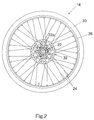
- Figure 2 is a side elevational view of the rear wheel of the bicycle illustrated in Figure 1 with the sprockets removed;
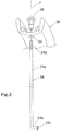
- Figure 3 is partially exploded perspective view of the rim, one of the spokes and one of the spoke nipples of the bicycle illustrated in Figure 1;
- Figure 4 is a side elevational view of the rear brake disc hub of the rear wheel illustrated in Figure 2 with the sprockets removed;
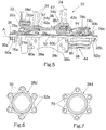
- Figure 5 is a side elevational view of the rear brake disc hub of the rear wheel illustrated in Figure 3 with certain portions broken away for purposes of illustration;
- Figure 6 is a left end elevational view of the rear brake disc hub body illustrated in Figures 4 and 5 with the brake disc rotor bolts mounted thereto;
- Figure 7 is a left end elevational view of the rear brake disc hub body illustrated in Figures 4 and 5 with the brake disc rotor bolts removed;
- Figure 8 is an enlarged side elevational view of the rear brake disc hub body of the rear brake disc hub illustrated in Figures 4 and 5 with the rotor removed;
- Figure 9 is a partial transverse cross-sectional view of the rear brake disc hub body illustrated in Figures 4, 5 and 8 as seen along section line 9-9 of Figure 8;
- Figure 10 is a partial transverse cross-sectional view of the rear brake disc hub body illustrated in Figures 4, 5 and 8 as seen along section line 10-10 of Figure 8;
- Figure 11 is a partial transverse cross-sectional view of the rear brake disc hub body illustrated in Figures 4, 5 and 8 as seen along section line 11-11 of Figure 8;
- Figure 12 is a partial transverse cross-sectional view of the rear brake disc hub body illustrated in Figures 4, 5 and 8 as seen along section line 12-12 of Figure 8;
- Figure 13 is a partial transverse cross-sectional view of the rear brake disc hub body illustrated in Figures 4, 5 and 8 as seen along section line 13-13 of Figure 8;
- Figure 14 is a partial transverse cross-sectional view of the rear brake disc hub body illustrated in Figures 4, 5 and 8 as seen along section line 14-14 of Figure 8;
- Figure 15 is a partial transverse cross-sectional view of the rear brake disc hub body illustrated in Figures 4, 5 and 8 as seen along section line 15-15 of Figure 8;
- Figure 16 is a partial transverse cross-sectional view of the rear brake disc hub body illustrated in Figures 4, 5 and 8 as seen along section line 16-16 of Figure 8;
- Figure 17 is an enlarged, partial outside elevational view of one of the spoke openings of the rear brake disc hub body illustrated in Figures 4, 5 and 8;
- Figure 18 is an inside elevational view of the spoke opening illustrated in Figure 17; and
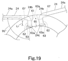
- Figure 19 is an enlarged, schematic view of portion of the rear brake disc hub body illustrated in Figures 4, 5 and 8 with two spokes extending outwardly therefrom.
-
- Referring initially to Figures 1-3, a
bicycle 10 is illustrated with certain parts being modified in accordance with the present invention as discussed below. Thebicycle 10 basically has aframe 12 with afront fork 13 movably coupled thereto. Arear wheel 14 is rotatably coupled to a rear portion of theframe 12, while afront wheel 16 is rotatably coupled to thefront fork 13. Theframe 12 also has aseat 18 adjustably coupled toframe 12, ahandlebar 19 coupled to thefront fork 13 for turning thefront wheel 16 and adrive train 20 for propelling thebicycle 10. Thebicycle 10 is also provided with a pair ofdisc brake assemblies 21 having acaliper 21a and abrake lever 21b. - Since these parts of the
bicycle 10 are well known in the art, these parts will not be discussed or illustrated in detail herein, except as they are modified in accordance with the present invention. Moreover, various conventional bicycle parts such as brakes, derailleurs, additional sprocket, etc., which are not illustrated and/or discussed in detail herein, can be used in conjunction with the present invention. - As seen in Figure 2, the
rear wheel 14 has arear hub 22, a plurality ofspokes 24 extending outwardly from therear hub 22, arim 26 coupled to the outer ends ofspokes 24 by spokenipples 28, and atire 30 located on the outer surface ofrim 26. Therear hub 22 is also provided with abrake disc rotor 32 that is attached to therear hub 22 by sixbolts 32a and sixnuts 32b, as explained below. It will be apparent to those skilled in the art from this disclosure that a variety of spoke arrangements are possible without departing from the present invention. For example, a twenty-four spoke wheel, a twenty-eight spoke wheel, a thirty-two spoke wheel, a thirty-six spoke wheel or a forty spoke wheel can be constructed in accordance with the present invention without departing from the present invention. Basically, the number of spokes depends upon the rim (which is conventional) and the arrangement (number) of spoke openings of the hub of the present invention. In any event, conventional spoking arrangements are utilized with the hub of the present invention. - Preferably, the
spokes 24, therim 26 and spokenipples 28 are all conventional parts that are used with therear hub 22 of the present invention as seen in Figure 3. In other words, the unique design of therear hub 22 allows it to be used with conventional parts, e.g.,tangential spokes 24 and aconventional rim 26. Accordingly, when therear wheel 14 is assembled, thespokes 24 extend tangentially from an imaginary circle centered on the center axis of rotation ofrear hub 22. Preferably an even number ofspokes 24 are coupled torim 26 in a conventional spoking arrangement (with the outer ends circumferentially equally spaced from each other). Moreover, the number of spokes corresponds to two times the number of spoke openings ofrear hub 22, as discussed below in more detail. - The term "tangential spokes" are spokes that have a
straight section 24a and abent end 24b with anenlarged head 24c such thatstraight section 24a extends at an angle of about 95° relative to thebent end 24b. Such spokes are well known in the bicycle art. As seen in Figure 3, thespokes 24 of the illustrated embodiment each have an outer threadedend 24d that is located at the opposite end of the centerstraight section 24a from thebent end 24b (inner end portion) with theenlarged head 24c. Thebent end 24b has a center axis that forms an angle of about 95° with the center axis of thestraight section 24a. The bent ends 24b of thespokes 24 are designed to be received within the first and second spoke openings. In particular, theenlarged heads 24c of thespokes 24 engage an interior surface of thehub body 38 with thestraight sections 24a extending substantially tangentially to an imaginary circle with a center on the center axis of rotation of therear hub 22. - The
rim 26 can be any conventional rim that has a plurality of spoke holes 34 for receiving the spoke nipples 28 for attaching the outer threaded ends 24d of thespokes 24 thereto. In the illustrated embodiment, therim 26 is a conventional steel or alloy rim having a U-shaped cross section with the spoke holes 34 formed therein. The spoke holes 34 are equally spaced apart in a circumferential direction. The spoke holes 34 preferably lie in a single plane P that divides the cross section in half as seen in Figure 3. Of course, rims with fewer or more spoke holes 34 can be used with a hub of the present invention, if needed and/or desired. For example, therim 26 can have twenty-four, twenty-eight, thirty two, thirty-six or forty spoke holes depending on the number of spoke openings of therear hub 22 as explained below. - As best seen in Figure 5, the
rear hub 22 basically includes ahub axle 36, a hub body orshell 38, afreewheel 44 and aquick release mechanism 46. Of the parts ofrear hub 22, only thehub body 38 is a non-conventional part. The remaining parts ofrear hub 22 are relatively conventional, and thus, the remaining parts ofrear hub 22 will not be discussed or illustrated in detail herein. - Of course, it will be apparent to those skilled in the art that the front hub 22' is preferably constructed in accordance with the present invention. In other words, the front hub 22'has the same basic construction of the
rear hub 22, except that the front hub 22' does not have a freewheel. Thus, the construction of the front hub 22' will not be discussed or illustrated in detail herein - As seen in Figure 5, the
hub axle 36 has a center axis A extending between afirst end 36a and asecond end 36b. Thequick release mechanism 46 extends through acenter bore 36c of thehub axle 36 such that thequick release mechanism 46 is coupled to thehub axle 36 in a conventional manner. The first and second ends 36a and 36b of thehub axle 36 are threaded for receiving a pair of nuts 50a and 50b that apply an axial force on thehub body 38, thebearing assemblies freewheel 44. The first andsecond bearing assemblies hub body 38 with thefreewheel 44 on thehub axle 36. Thefreewheel 44 allows thehub body 38 to rotate freely relative to the rear sprockets (not shown) in one direction, but fixedly couples the rear sprockets relative to thehub body 38 in the opposite rotational direction in a conventional manner. - The
hub body 38 is illustrated in accordance with the present invention. In this embodiment, thehub body 38 is a hollow member that defines aninterior passageway 52 with thehub axle 36 being rotatably supported therein by the first andsecond bearing assemblies hub body 38 is a substantially tubular member. Specifically, thehub body 38 has a centertubular portion 38c with first andsecond end sections tubular portion 38c as a one-piece, unitary member. Thefirst end section 38a has an integrally mounted brakerotor attachment portion 38d, while asecond end section 38b has thefreewheel 44 fixedly coupled thereto. - As seen in Figures 8-19, the
hub body 38 has a set of first spokeopenings 60a provided at thefirst end section 38a of thehub body 38 for receiving the bent ends 24b of thespokes 24. Similarly, thesecond end section 38b of thehub body 38 is provided with a second set ofspoke openings 60b for receiving the bent ends 24b of thespokes 24. The number ofspoke openings rim 26 and the number ofspokes 24. The total number ofspoke openings spokes 24.First end section 38a preferably has a slightly smaller diameter (internal and external diameters) thansecond end section 38b. The first and second end sections 28a and 28b preferably have the same radial thickness and are relatively thick, as discussed below in more detail. Thespoke openings hub body 38. Preferably, the number of first spokeopenings 60a is equal to the number of second spokeopenings 60b. Of course, the number of first spokeopenings 60a can be different from the number of second spokeopenings 60b. In any event, each of thespoke openings spokes 24 as explained below. Accordingly, therear hub 22 is designed to have a plurality of spokes extending outwardly therefrom in a generally tangential direction. - Preferably, the first and second sets of
spoke openings openings tangential spokes 24. Of course, it is possible that the first and second sets ofspoke openings tangential spokes 24 are used in one end of thehub body 38 and different types of spokes are used in the other end of thehub body 38. The first spokeopenings 60a are circumferentially arranged around thehub body 38 adjacent to the brakerotor attachment portion 38d. Preferably, the first spokeopenings 60a are spaced axially inward of the brakerotor attachment portion 38d so thatbrake disc rotor 32 can be easily attached with thebolts 32a and nuts 32b. - In this embodiment, the first and second spoke
openings insertion portion 61 and a pair of retainingportions 62. Accordingly, each of thespoke openings spokes 24 retained therein with thespokes 24 extending in opposite directions. - The
insertion portion 61 of each spoke opening is located between the pair of retainingportions 62 of each spoke opening. Eachinsertion portion 61 is formed by a pair of opposedcurved surfaces 64 that are spaced apart so as to be equal to or slightly larger than the widths or diameters of theenlarged heads 24c of thespokes 24. Thus, the inner ends (bent ends 24b withenlarged heads 24c) of thespokes 24 can be easily inserted into thespoke openings insertion portions 61. - The retaining
portions 62 have smaller widths or diameters than theinsertion portions 61. More specifically, the diameters or widths of the retainingportions 62 are smaller than the diameters or widths of theenlarged heads 24c of thespokes 24 so as to retain thespokes 24 within thespoke openings portions 62 are each preferably defined by a partialcylindrical surface 66 that is connected to thecurved surfaces 64 of the associatedinsertion portion 61 by a pair ofstraight surfaces 68. - The internal surface of
hub body 38 preferably includes a plurality of internalhead receiving seats 63 located adjacent the retainingportions 62 of the first and second spokeopenings internal abutment 65 is arranged between each of theinsertion portions 61 and each of the head receiving seats 63. Preferably, twointernal abutments 65 are arranged between each of theinsertion portions 61 and each of the head receiving seats 63. Each of theinternal abutments 65 are spaced a distance from the outer surface of thehub body 38 larger than a length of the bent ends 24b of each of thespokes 24. Thus, the bent ends 24b of thespokes 24 are retained in the retainingportions 62 of the first and second spokeopenings - Each of the
head receiving seats 63 is basically formed as a recess with ahead contact surface 63a. Thehead contact surface 63a of thehead receiving seat 63 is spaced a distance from the external surface of thehub body 38 not larger than the corresponding length of the bent ends 24b of thespokes 24. Each of thehead receiving seats 63 extends inwardly from the internal surface of thehub body 38 along a respective center axis C2 of the respective retainingportion 62. More specifically, eachhead contact surface 63a is spaced fromflute portions 67 formed in the external surface of thehub body 38, as discussed in more detail below. Each of thehead contact surfaces 63a is spaced radially outwardly from the internal surface of thehub body 38 such that the internal surface of thehub body 38 forms theinternal abutments 65. Preferably, the head contact surfaces 63a are frustoconical surfaces that correspond to the shapes of the bent ends 24b of thespokes 24 - The
hub body 38 has a thickness adjacent the first and second spokeopenings bent portions 24b of thespokes 24. However, the effective thickness of thehub body 38 is reduced due to thehead receiving seats 63 and theflute portions 67. In any event, the external surface of thehub body 38, thehead receiving seats 63 and theabutments 65 are dimensioned and configured to retain the bent ends 24b of thespokes 24 in the retainingportions 62 of the first and second spokeopenings head receiving seats 63 is spaced a distance from each of theflute portions 67 not larger than the length of thebent portions 24b of thespokes 24. Thus, theflute portions 67 hold thespokes 24 at the correct orientation. - As best seen in Figures 9 and 10, the
flute portions 67 are formed in the external surface of thehub body 38 and extend tangentially outward from each of the retainingportions 62. Thus, theflute portions 67 form a plurality of recesses in the external surface adjacent each of the retainingportions 62 as best seen in Figures 17 and 18. The retainingportions 62 and theflute portions 67 are dimensioned and configured to retain the bent ends 24b of thespokes 24 in the retainingportions 62 of the first and second spokeopenings flute portion 67 includes a concave curved surface configured to allow the inner end of eachstraight section 24a of each spoke 24 to be recessed and retained therein. Each of theflute portions 67 extends at substantially a right angle relative to respective center longitudinal axes C2 of each of the retainingportions 62. Theflute portions 67 are angled relative to the overall length of thespoke openings spokes 24 does not cause the spoke to move into theinsertion portions 61. Moreover, theflute portions 67 are angled relative to a plane that is perpendicular to the axis A. - The
spokes 24 are installed in the spoke openings by first inserting the inner ends (bent ends 24b withenlarged heads 24c) of thespokes 24 into theinsertion portions 61 of thespoke openings spokes 24 are pulled into the retainingportions 62 of thespoke openings straight portions 24a of thespokes 24 rest in theflute portions 67. Theinternal abutments 65 and theflute portions 67 cooperate together to hold thespokes 24 in the retainingportions 62 of thespoke openings - The
spoke openings insertion portions 61 are arranged in a circumferential pattern with one set of the retainingportions 62 being located axially outward from theinsertion portions 61 and the other set of retainingportions 62 being spaced axially inward from theinsertion portions 61. In other words, a first set of retainingportions 62 form an outer circumferential row of the retainingportions 62, and a second set of the retainingportions 62 form an inner circumferential row of retainingportions 62 with theinsertion portions 61 being located between the rows of retainingportions 62. - Preferably, the
insertion portion 61 and the retainingportions 62 of each spoke opening are formed simultaneously. Also preferably, the inner and outer ends of the retainingportions 62 of thespoke openings spokes 24. Each retainingportion 61 has a length L1 slightly smaller than a length of eachbent end 24b of each spoke 24 received therein. The thickness of eachend portion bent end 24b of each spoke 24. The length L1 is measured between the internal and external edges of the external and internal tapered surfaces of each retainingportion 62, respectively. As mentioned above, the retainingportions 62 of thespoke openings portions 62 of thespoke openings insertion portions 61 are also are spaced apart by an angle . - Each of the
insertion portions 61 has a center longitudinal axis C1 that passes through the center axis A of thehub axle 36 as best seen in Figures 12 and 15. The retainingportions 62, on the other hand, have center longitudinal axes C2 do not pass through the center axis A of thehub axle 36. Rather, the center longitudinal axes C2 of the retainingportions 62 are parallel to the center longitudinal axis C1 of theinsertion portion 61 for each of thespoke openings portions 62 results in thestraight sections 24a of thespokes 24 being easily arranged in a tangential direction relative to an imaginary circle centered on thehub body 38. Moreover, this angled configuration of the retainingportions 62 allows thestraight sections 24a of thespokes 24 to be easily aligned with the spoke holes 34 of therim 26 without significant bending of thespokes 24. In the illustrated embodiment, thespokes 24 are not bent more than about five degrees. Of course, the less thespokes 24 are bent the better. - If the retaining
portions 62 were formed with their center axis passing through the center axis A of thehub axle 36, then theconventional spokes 24 would be placed under excessive bending forces, which could result in thespokes 24 breaking during use of the wheel. In contrast, with the retainingportions 62 of thespokes 24 being angled, the amount of bending of thespokes 24 can be reduced and/or eliminated. - Referring to Figures 5-7, the brake
rotor attachment portion 38d is integrally formed with the centertubular portion 38c of thehub body 38 as a one-piece, unitary member. In the illustrated embodiment, the brakerotor attachment portion 38d is formed with six attachment members or points with threaded throughbores 70. While six individual attachment points are illustrated, it will be apparent to those skilled in the art from this disclosure that fewer or more attachment points can be utilized. Moreover, it will be apparent to those skilled in the art from this disclosure that the attachment portions could be a continuous flange, if needed and/or desired. - The through
bore 70 can be threaded or unthreaded. By using throughbores 70 instead of blind bores, therear hub 22 can be easily manufactured at a relatively lower cost. In the case of unthreaded through bores (not shown), thebolts 32a extend into openings in thebrake disc rotor 32 and then through the through bores. The free ends of thebolts 32a have nuts 32b threaded thereon for attaching thebrake disc rotor 32 to thehub body 38. This arrangement allows thehub body 38 and the brakerotor attachment portion 38d to be formed out of the same a lightweight material, such as aluminum. In this arrangement, thehub body 38 does not need to be replaced if the through bores 70 become damaged. - In the case of threaded through bores 70 (of the illustrated embodiment), the
bolts 32a extend into openings in thebrake disc rotor 32 and then threaded into the through bores 70. Optionally, the free ends of thebolts 32a can have the nuts 32b threaded thereon for more securely attaching thebrake disc rotor 32 to thehub body 38. In this arrangement, if the threads of throughbores 70 become damaged, thehub body 38 does not need to be replaced. Rather, thebolts 32a and the nuts 32b securely attach thebrake disc rotor 32 to thehub body 38. -
Bearing assemblies hub body 38 onhub axle 36. The bearingassembly 40a basically includes a plurality ofballs 74a located between aninner race member 76a and anouter race member 78a. Similarly, the bearingassembly 40b basically includes a plurality ofballs 74b located between aninner race member 76b and anouter race member 78b. Since bearingassemblies - A pair of
spoke seals interior passageway 52 of thehub body 38 so as to be adjacent thespoke openings spoke openings hub axle 36, and/or parts of thefreewheel 44. In other words, the spoke seals 42a and 42b prevent contaminants from entering therear hub 22 through thespoke openings - In the illustrated embodiment, the
spoke seal 42a has a tubular section and a pair of ends. The ends are configured to engage an abutment of the inner surface of the hub body 38 (at an inner end), and an inner surface of the outer race of bearingassembly 40a. Of course, the particular shape of the ends ofspoke seal 42a will vary depending on the shape of thehub body 38 and its internal components. In any event, when therear hub 22 is assembled, an axial force is applied to the ends of thespoke seal 42a to form annular seals therebetween. Thus, thespoke seal 42a forms an isolated area beneath thespoke openings 60a. This isolated area beneath thespoke openings 60a is a continuous annular space. - Similar to the
spoke seal 42a, thespoke seal 42b forms an isolated area beneath thespoke openings 60b. Thus, contaminates are prevented from enteringrear hub 22. The isolated area beneath thespoke openings 60b is a continuous annular space. The exact structure ofseals - The freewheel, such as the
freewheel 44, are well known in the bicycle art, and thus, thefreewheel 44 will not be illustrated or discussed in detail herein. Thefreewheel 44 is used to transmit a driving force from the chain to the rear bicycle wheel in one rotation direction only. Thefreewheel 44 allows thebicycle 10 to advance freely without any rotation of the pedals. Thefreewheel 44 is fastened to therear hub 22 as integral part of therear hub 22 in a conventional manner. Thefreewheel 44 has an outertubular part 94, an innertubular part 96 and a one-way clutch 98. The innertubular part 96 is installed radially inwardly of the outertubular part 94 so that the innertubular part 96 is free to rotate relative to the outertubular part 94. The one-way clutch 98 is installed between the outertubular part 94 and innertubular part 96 for transmitting the driving force from the outertubular part 94 to the innertubular part 96 in one rotational direction only. The outertubular part 94 has a plurality of gears or sprockets (not shown) mounted thereon, while the innertubular part 96 is usually mounted on thehub axle 36. - The terms of degree such as "substantially", "about" and "approximately" as used herein mean a reasonable amount of deviation of the modified term such that the end result is not significantly changed. These terms should be construed as including a deviation of at least ± 5% of the modified term if this deviation would not negate the meaning of the word it modifies.
- While only selected embodiments have been chosen to illustrate the present invention, it will be apparent to those skilled in the art from this disclosure that various changes and modifications can be made herein without departing from the scope of the invention as defined in the appended claims. Furthermore, the foregoing description of the embodiments according to the present invention are provided for illustration only, and not for the purpose of limiting the invention as defined by the appended claims and their equivalents.
Claims (18)
- A bicycle hub suitable for use with tangential bicycle spokes having a straight section and a bent end with an enlarged head, said bicycle hub comprising:a hub axle (36) having a center axis extending between a first end (36a) and a second end (36b); anda hub body (38) having an interior passageway (52) with said hub axle (36) being rotatably supported therein, an external surface, an internal surface and a set of first spoke openings (60a) circumferentially arranged around said hub body (38) and extending between said external and internal surfaces,each of said first spoke openings (60a) having an insertion portion (61) with a width dimensioned so as to permit the enlarged head of a tangential spoke to pass therethrough and a retaining portion (62) with a width dimensioned to be smaller than said width of said insertion portion (61), so as to retain the enlarged head of the tangential spoke therein,an internal head receiving seat (63) arranged to adjoin each of said retaining portions (62) from the inside of said first spoke openings (60a) and an internal abutment (65) arranged between each of said insertion portions (61) and each of said head receiving seats (63).
- The bicycle hub according to claim 1, wherein each of said internal abutments (65) defines a radial distance out to said external surface of said hub body (38) which is larger than a length of the bent end of each of the spokes so as to retain the bent ends of the spokes in said retaining portions (62) of said spoke openings (60a).
- The bicycle hub according to claims 1, 2 or 3, wherein each of said head receiving seats (63) is formed as a recess extending into said internal surface about a center axis (C2) of each of said retaining portions (62).
- The bicycle hub according to any one of the claims 1 to 4, wherein each of said head receiving seats (63) includes a contact surface (63a) disposed radially outwardly from said internal surface of said hub body (38) such that a portion of said internal surface forms said abutment (65).
- The bicycle hub according to any one of the claims 1 to 5, wherein portions of said internal surface of said hub body (38) define a pair of said abutments (65) arranged between said retaining portion (62) and said insertion portion (61) of each of said first spoke openings (60a).
- The bicycle hub according to claim 1, wherein said hub body (38) has a thickness in the region of said first spoke openings (60a) which is larger than the length of the bent portions of the spokes.
- The bicycle hub according to any one of the claims 1 to 6, wherein said external surface has a flute portion (67) extending from each of said retaining portions (62) so as to form a recess in said external surface adjacent each of said retaining portions (62).
- The bicycle hub according to claim 8, wherein each of said head receiving seats (63) includes a head contact surface (63a) disposed at a radial distance from each of said flute portions (67) which is not larger than the length of the bent portions of the spokes.
- The bicycle hub according to any one of the claims 1 to 8, wherein said external surface, said head receiving seats (63) and said abutments (65) are dimensioned and configured so as to retain the bent ends of the spokes in said retaining portions (62) of said first spoke openings (60a).
- A bicycle hub suitable for use with tangential bicycle spokes having a straight section and a bent end with an enlarged head, said bicycle hub comprising:a hub axle (36) having a center axis extending between a first end and a second end; anda hub body (38) having an interior passageway (52) with said hub axle being rotatably supported therein, an external surface, an internal surface and a set of first spoke openings (60a) circumferentially arranged around said hub body (38) and extending between said external and internal surfaces,each of said first spoke openings (60a) having an insertion portion (61) with a width dimensioned so as to permit the enlarged head of a tangential spoke to pass therethrough and a retaining portion with a width dimensioned to be smaller than said width of said insertion portion, so as to retain the enlarged head of the tangential spoke therein,said external surface having a flute portion (67) extending from each of said retaining portions (62) to form a recess in said external surface adjacent each of said retaining portions (62), said retaining portions (62) and said flute portions (67) being dimensioned and configured to retain the bent ends of the spokes in said retaining portions (62) of said first spoke openings (60a).
- The bicycle hub according to claim 10, wherein each of said flute portions (67) includes a concave curved surface.
- The bicycle hub according to claims 10 or 11, wherein each of said flute portions (67) extends at substantially a right angle relative to a center longitudinal axis (C2) of each of said retaining portions (62).
- The bicycle hub according to claim 12, wherein an internal head receiving seat (63) is arranged to adjoin each of said retaining portions (62) from the inside of said spoke openings (60a) and an internal abutment (65) is arranged between each of said insertion portions (61) and each of said head receiving seats (63).
- The bicycle hub according to claim 13, wherein each of said head receiving seats (63) includes a head contact surface (63a) disposed at a radial distance from each of said flute portions (67), which is not larger than the length of the bent portions of the spokes.
- The bicycle hub according to claim 10, wherein a head contact surface (63a) is arranged to adjoin each of said retaining portions (62) so as to define a radial distance to each of said flute portions (67), which is not larger than the length of the bent portions of the spokes.
- The bicycle hub according to any one of the claims 1 to 15, further comprising a brake disc rotor (32).
- The bicycle hub according to any one of the claims 1 to 16, further comprising a freewheel (44) attached to one end of the hub body (38).
- The bicycle wheel comprising a bicycle hub (38) as defined in any one of the claims 1 to 17, a plurality of tangential spokes (24) having a bent end and an enlarged head (24c) for securement to the hub body (38) and an annular rim (26) coupled to the outer ends of the spokes (24).
Applications Claiming Priority (2)
| Application Number | Priority Date | Filing Date | Title |
|---|---|---|---|
| US870020 | 2001-05-31 | ||
| US09/870,020 US6485108B1 (en) | 2001-05-31 | 2001-05-31 | Bicycle hub |
Publications (2)
| Publication Number | Publication Date |
|---|---|
| EP1262335A2 true EP1262335A2 (en) | 2002-12-04 |
| EP1262335A3 EP1262335A3 (en) | 2005-02-02 |
Family
ID=25354628
Family Applications (1)
| Application Number | Title | Priority Date | Filing Date |
|---|---|---|---|
| EP02011265A Withdrawn EP1262335A3 (en) | 2001-05-31 | 2002-05-22 | Bicycle hub |
Country Status (6)
| Country | Link |
|---|---|
| US (1) | US6485108B1 (en) |
| EP (1) | EP1262335A3 (en) |
| JP (1) | JP3727286B2 (en) |
| CN (1) | CN1265978C (en) |
| CZ (1) | CZ20021809A3 (en) |
| TW (1) | TW523472B (en) |
Cited By (2)
| Publication number | Priority date | Publication date | Assignee | Title |
|---|---|---|---|---|
| EP1566288A3 (en) * | 2004-02-20 | 2006-10-11 | Shimano Inc. | Bicycle hub |
| TWI731963B (en) * | 2016-04-26 | 2021-07-01 | 瑞士商Dt瑞士公司 | Hub and wheel |
Families Citing this family (8)
| Publication number | Priority date | Publication date | Assignee | Title |
|---|---|---|---|---|
| US6666525B1 (en) * | 2002-06-17 | 2003-12-23 | David J. Schroepfer | Spoked wheel apparatus |
| US7360847B2 (en) * | 2005-05-27 | 2008-04-22 | Shimano Inc. | Bicycle hub |
| US7306292B2 (en) * | 2005-05-27 | 2007-12-11 | Shimano Inc. | Bicycle hub |
| US20070284934A1 (en) * | 2006-06-13 | 2007-12-13 | Kun Teng Industry Co., Ltd. | Hub for assembly with straight spokes |
| US7837213B2 (en) * | 2007-04-16 | 2010-11-23 | Trek Bicycle Corporation | Bicycle rear wheel suspension system |
| WO2010148263A1 (en) * | 2009-06-18 | 2010-12-23 | Oclaro (New Jersey) Inc | Accurately tunable laser source |
| JP2011201398A (en) * | 2010-03-25 | 2011-10-13 | Honda Motor Co Ltd | Motorcycle wheel |
| US9815322B2 (en) * | 2015-01-19 | 2017-11-14 | Shimano Inc. | Bicycle hub and bicycle wheel assembly |
Family Cites Families (15)
| Publication number | Priority date | Publication date | Assignee | Title |
|---|---|---|---|---|
| DE99859C (en) | 1897-12-21 | |||
| US553616A (en) | 1896-01-28 | Thomas v | ||
| FR2257439B1 (en) * | 1973-10-10 | 1976-10-01 | Roulements Soc Nouvelle | |
| DE8703618U1 (en) | 1987-03-11 | 1987-06-04 | Weco Wehmeyer & Co Fahrzeug-Fahrzeugteile-Werke GmbH & Co, 33824 Werther | Wheel for two-wheelers |
| US5429421A (en) * | 1994-02-08 | 1995-07-04 | Watson; Paul B. | Hub for a spoked wheel |
| US5626401A (en) * | 1994-05-17 | 1997-05-06 | Innovative Bicycle Components Company | Spoked wheel hub |
| US5795036A (en) | 1995-05-26 | 1998-08-18 | Campagnolo S.R.L. | Bicycle rear wheel |
| FR2739059B1 (en) | 1995-09-22 | 1997-12-12 | Mavic Sa | WHEEL HUB, ESPECIALLY FOR A CYCLE |
| JP3069284B2 (en) | 1996-01-26 | 2000-07-24 | 株式会社シマノ | Bicycle hub |
| DE19724327B4 (en) | 1997-06-10 | 2009-01-29 | Sram Deutschland Gmbh | Hub for a spoked wheel |
| JP2000264006A (en) | 1999-03-17 | 2000-09-26 | Takatsugu Nakano | Hub for wheels |
| US6354669B1 (en) * | 2000-01-31 | 2002-03-12 | Shimano Inc. | Bicycle hub for tangential spokes |
| US6309028B1 (en) * | 2000-01-31 | 2001-10-30 | Shimano Inc. | Bicycle hub |
| US6511133B1 (en) * | 2000-01-31 | 2003-01-28 | Shimano Inc. | Bicycle hub with spoke seal |
| US6352314B1 (en) * | 2000-01-31 | 2002-03-05 | Shimano Inc. | Bicycle hub for disc brake |
-
2001
- 2001-05-31 US US09/870,020 patent/US6485108B1/en not_active Expired - Fee Related
-
2002
- 2002-03-06 TW TW091104147A patent/TW523472B/en not_active IP Right Cessation
- 2002-04-11 CN CN02105831.8A patent/CN1265978C/en not_active Expired - Fee Related
- 2002-05-20 JP JP2002144214A patent/JP3727286B2/en not_active Expired - Fee Related
- 2002-05-22 EP EP02011265A patent/EP1262335A3/en not_active Withdrawn
- 2002-05-24 CZ CZ20021809A patent/CZ20021809A3/en unknown
Non-Patent Citations (1)
| Title |
|---|
| None |
Cited By (4)
| Publication number | Priority date | Publication date | Assignee | Title |
|---|---|---|---|---|
| EP1566288A3 (en) * | 2004-02-20 | 2006-10-11 | Shimano Inc. | Bicycle hub |
| US7360952B2 (en) * | 2004-02-20 | 2008-04-22 | Shimano Inc. | Bicycle hub |
| US7413350B2 (en) | 2004-02-20 | 2008-08-19 | Shimano Inc. | Bicycle hub |
| TWI731963B (en) * | 2016-04-26 | 2021-07-01 | 瑞士商Dt瑞士公司 | Hub and wheel |
Also Published As
| Publication number | Publication date |
|---|---|
| US20020180254A1 (en) | 2002-12-05 |
| TW523472B (en) | 2003-03-11 |
| JP3727286B2 (en) | 2005-12-14 |
| CN1265978C (en) | 2006-07-26 |
| JP2003019902A (en) | 2003-01-21 |
| CZ20021809A3 (en) | 2003-11-12 |
| EP1262335A3 (en) | 2005-02-02 |
| CN1389356A (en) | 2003-01-08 |
| US6485108B1 (en) | 2002-11-26 |
Similar Documents
| Publication | Publication Date | Title |
|---|---|---|
| US6431657B2 (en) | Bicycle hub for disc brake | |
| US6409282B1 (en) | Bicycle hub | |
| US6523659B2 (en) | Bicycle hub with tight connection ratchet and detachable freewheel | |
| EP1016553B1 (en) | Bicycle Wheel | |
| US6540306B2 (en) | Bicycle disc brake hub | |
| USRE42986E1 (en) | Bicycle disc brake hub | |
| EP1413506B1 (en) | Bicycle hub axle assembly | |
| US7306292B2 (en) | Bicycle hub | |
| US6485108B1 (en) | Bicycle hub | |
| US6309028B1 (en) | Bicycle hub | |
| US6354669B1 (en) | Bicycle hub for tangential spokes | |
| US6511133B1 (en) | Bicycle hub with spoke seal | |
| US20070090686A1 (en) | Bicycle wheel component |
Legal Events
| Date | Code | Title | Description |
|---|---|---|---|
| PUAI | Public reference made under article 153(3) epc to a published international application that has entered the european phase |
Free format text: ORIGINAL CODE: 0009012 |
|
| AK | Designated contracting states |
Kind code of ref document: A2 Designated state(s): AT BE CH CY DE DK ES FI FR GB GR IE IT LI LU MC NL PT SE TR |
|
| AX | Request for extension of the european patent |
Free format text: AL;LT;LV;MK;RO;SI |
|
| PUAL | Search report despatched |
Free format text: ORIGINAL CODE: 0009013 |
|
| AK | Designated contracting states |
Kind code of ref document: A3 Designated state(s): AT BE CH CY DE DK ES FI FR GB GR IE IT LI LU MC NL PT SE TR |
|
| AX | Request for extension of the european patent |
Extension state: AL LT LV MK RO SI |
|
| 17P | Request for examination filed |
Effective date: 20050421 |
|
| AKX | Designation fees paid |
Designated state(s): DE FR GB IE IT NL |
|
| RAP1 | Party data changed (applicant data changed or rights of an application transferred) |
Owner name: SHIMANO INC. |
|
| STAA | Information on the status of an ep patent application or granted ep patent |
Free format text: STATUS: THE APPLICATION IS DEEMED TO BE WITHDRAWN |
|
| 18D | Application deemed to be withdrawn |
Effective date: 20071201 |