EP1262334A2 - Bicycle wheel - Google Patents
Bicycle wheel Download PDFInfo
- Publication number
- EP1262334A2 EP1262334A2 EP02250840A EP02250840A EP1262334A2 EP 1262334 A2 EP1262334 A2 EP 1262334A2 EP 02250840 A EP02250840 A EP 02250840A EP 02250840 A EP02250840 A EP 02250840A EP 1262334 A2 EP1262334 A2 EP 1262334A2
- Authority
- EP
- European Patent Office
- Prior art keywords
- tire retaining
- section
- retaining walls
- spokes
- hub
- Prior art date
- Legal status (The legal status is an assumption and is not a legal conclusion. Google has not performed a legal analysis and makes no representation as to the accuracy of the status listed.)
- Granted
Links
Images


Classifications
-
- B—PERFORMING OPERATIONS; TRANSPORTING
- B60—VEHICLES IN GENERAL
- B60B—VEHICLE WHEELS; CASTORS; AXLES FOR WHEELS OR CASTORS; INCREASING WHEEL ADHESION
- B60B21/00—Rims
- B60B21/06—Rims characterised by means for attaching spokes, i.e. spoke seats
- B60B21/066—Rims characterised by means for attaching spokes, i.e. spoke seats the spoke mounting means being located on a flange oriented radially and formed on the radially inner side of the rim well
-
- B—PERFORMING OPERATIONS; TRANSPORTING
- B60—VEHICLES IN GENERAL
- B60B—VEHICLE WHEELS; CASTORS; AXLES FOR WHEELS OR CASTORS; INCREASING WHEEL ADHESION
- B60B1/00—Spoked wheels; Spokes thereof
- B60B1/02—Wheels with wire or other tension spokes
- B60B1/0215—Wheels with wire or other tension spokes characterised by specific grouping of spokes
-
- B—PERFORMING OPERATIONS; TRANSPORTING
- B60—VEHICLES IN GENERAL
- B60B—VEHICLE WHEELS; CASTORS; AXLES FOR WHEELS OR CASTORS; INCREASING WHEEL ADHESION
- B60B1/00—Spoked wheels; Spokes thereof
- B60B1/02—Wheels with wire or other tension spokes
- B60B1/04—Attaching spokes to rim or hub
- B60B1/041—Attaching spokes to rim or hub of bicycle wheels
-
- B—PERFORMING OPERATIONS; TRANSPORTING
- B60—VEHICLES IN GENERAL
- B60B—VEHICLE WHEELS; CASTORS; AXLES FOR WHEELS OR CASTORS; INCREASING WHEEL ADHESION
- B60B1/00—Spoked wheels; Spokes thereof
- B60B1/02—Wheels with wire or other tension spokes
- B60B1/04—Attaching spokes to rim or hub
- B60B1/042—Attaching spokes to hub
-
- B—PERFORMING OPERATIONS; TRANSPORTING
- B60—VEHICLES IN GENERAL
- B60B—VEHICLE WHEELS; CASTORS; AXLES FOR WHEELS OR CASTORS; INCREASING WHEEL ADHESION
- B60B21/00—Rims
- B60B21/02—Rims characterised by transverse section
- B60B21/025—Rims characterised by transverse section the transverse section being hollow
-
- B—PERFORMING OPERATIONS; TRANSPORTING
- B60—VEHICLES IN GENERAL
- B60B—VEHICLE WHEELS; CASTORS; AXLES FOR WHEELS OR CASTORS; INCREASING WHEEL ADHESION
- B60B21/00—Rims
- B60B21/06—Rims characterised by means for attaching spokes, i.e. spoke seats
- B60B21/062—Rims characterised by means for attaching spokes, i.e. spoke seats for bicycles
Definitions
- the present invention relates to a bicycle wheel, more particularly to a bicycle wheel with spokes that have end portions bent at a small angle to prevent breakage of the spokes.
- U.S. Patent No. 6,186,598 there is disclosed a bicycle wheel rim with an H-shaped cross-section.
- a plurality of hollow packing members are mounted on the wheel rim for reinforcing purposes.
- the packing members are formed with through holes aligned respectively with spoke mounting holes in the tire retaining walls of the wheel rim to permit installation of spokes on the wheel rim.
- the spokes have outer end portions mounted on the wheel rim and the packing members, and inner end portions to be mounted on a hub.
- the outer end portions of the spokes are generally bent by an angle greater than 90°. As such, the spokes are susceptible to breakage.
- the bicycle wheel thus requires a relative large number of the spokes so as to reduce the stress applied to an individual spoke.
- the main object of the present invention is to provide a bicycle wheel with spokes that have end portions bent at a small angle to prevent breakage of the spokes.
- the bicycle wheel of the present invention is adapted to be installed on a wheel axle, and includes a hub, a wheel rim, and a plurality of spokes .
- the hub is adapted to be mounted rotatably on the axle, and has left and right end portions which are opposite to each other along an axis of the axle. Each of the left and right end portions is formed with a set of spoke fastening holes which are arranged around the axis of the axle.
- the wheel rim is disposed around the hub.
- the wheel rim includes spaced-apart left and right annular tire retaining walls, each of which has a radial inner section proximate to the hub, a radial outer section distal to the hub, and an intermediate section between the radial inner and radial outer sections.
- the radial outer sections of the tire retaining walls are adapted for retaining a bicycle tire therebetween.
- the radial inner section of each of the tire retaining walls has a lateral inner surface confronting the radial inner section of another one of the tire retaining walls, and a lateral outer surface opposite to the lateral inner surface.
- each of the tire retaining walls is formed with a set of spoke mounting holes, each of which extends through the lateral outer surface and the lateral inner surface of the radial inner section of a respective one of the tire retaining walls .
- the wheel rim further includes an annular base wall interconnecting the intermediate sections of the tire retaining walls.
- Each of the spokes has an inner end portion mounted on a respective one of the spoke fastening holes in the left and right end portions of the hub, and an outer end portion mounted on a respective one of the spoke mounting holes in the radial inner section of a respective one of the tire retaining walls .
- each of the spokes includes an enlarged head abutting against the lateral outer surface of the radial inner section of a corresponding one of the tire retaining walls, an extending section connected to the enlarged head and received in the respective one of the spoke mounting holes, and a bending section connected to the extending section and disposed adjacent to the lateral inner surface of the radial inner section of the respective one of the tire retaining walls .
- the bending section is bent from the extending section, and extends from the extending section toward the inner end portion of the spoke.
- the preferred embodiment of the bicycle wheel 2 of the present invention is adapted to be installed on a wheel axle 20, and is shown to include a hub 21 adapted to be mounted rotatably on the axle 20, a wheel rim 1 disposed around the hub 21, and a plurality of spokes 23, 23' for mounting the wheel rim 1 on the hub 21.
- the hub 21 is sleeved rotatably and co-axially on the wheel axle 20, and has left and right end portions 211, 211' which are opposite to each other along an axis 201 of the axle 20.
- Each of the left and right end portions 211, 211' is formed with a set of spoke fastening holes 212 which are arranged around the axis 201 of the axle 20.
- the wheel rim 1 includes an integrally formed rim body which has spaced-apart left and right annular tire retaining walls 11, 11', an annular base wall 12 and an annular connecting wall 13.
- Each of the left and right tire retaining walls 11, 11' has a radial inner section 111 proximate to the hub 21 and to a central point of the wheel rim 1, a radial outer section 112 distal to the hub 21 and to the central point of the wheel rim 1, and an intermediate section 113 between the radial inner and radial outer sections 111, 112.
- the base wall 12 interconnects the intermediate sections 113 of the left and right tire retaining walls 11, 11'.
- the radial outer sections 112 of the left and right tire retaining walls 11,11' are adapted for retaining a bicycle tire 22 therebetween.
- the radial inner section 111 of each of the tire retaining walls 11, 11' has a lateral inner surface 114 confronting the radial inner section 111 of the other one of the tire retaining walls 11, 11', and a lateral outer surface 118 opposite to the lateral inner surface 114.
- the radial inner section 111 of each of the tire retaining walls 11, 11' is formed with a set of spoke mounting holes 115, each of which extends through the lateral inner surface 114 and the lateral outer surface 118 of the radial inner section 111 of the respective one of the tire retaining walls 11, 11'.
- the connecting wall 13 interconnects the radial inner sections 111 of the left and right tire retaining walls 11, 11', and has a left terminating end 131 connected to the lateral inner surface 114 of the radial inner section 111 of the left tire retaining wall 11, and a right terminating end 131' connected to the lateral inner surface 114 of the radial inner section 111 of the right tire retaining wall 11'.
- the connecting wall 13 further has a radial inner surface 132 confronting the hub 21, and a radial outer surface 135 opposite to the radial inner surface 132.
- Each of the left and right terminating ends 131, 131' of the connecting wall 13 is formed with a set of passage holes 133, each of which is communicated with a respective one of the spoke mounting holes 115 in an adjacent one of the tire retaining walls 11, 11', and each of which is formed through the radial inner surface 132 and the radial outer surface 135 of the connecting wall 13.
- Each of the tire retaining walls 11, 11' has a plurality of angularly displaced reinforcing projections 116 at a radial inner edge of the tire retaining walls 11, 11'.
- the reinforcing projections 116 project radially and inwardly relative to the connecting wall 13 and are aligned respectively, in radial directions, with the spoke mounting holes 115 in a respective one of the tire retaining walls 11, 11'.
- the bicycle tire 22 is installed on the wheel rim 1 and is retained between the radial outer sections 112 of the tire retaining walls 11, 11'.
- the bicycle tire 22 is in the form of an outer tire member.
- an air-tight air chamber 222 is formed among the radial outer sections 112 and the bicycle tire 22.
- a valve mounting hole 124 is formed through the base wall 12.
- the connecting wall 13 is formed with an access hole 136 registered with the valve mounting hole 124 for access to the latter.
- Each of the spokes 23, 23' has an inner end portion 231 mounted on a respective one the spoke fastening holes 212 in the left and right end portions 211, 211' of the hub 21, and an outer end portion 232 mounted on a respective one of the spoke mounting holes 115 in the radial inner section 111 of one of the tire retaining walls 11, 11'.
- a first set of the spokes 23 have their outer end portions 232 mounted on the left tire retaining wall 11 of the wheel rim 1, and have their inner end portions 231 mounted on the right end portion 211' of the hub 21.
- a second set of the spokes 23' have their outer end portions 232 mounted on the right tire retaining wall 11' of the wheel rim 1, and have their inner end portions 231 mounted on the left end portion 211 of the hub 21.
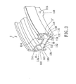
- the first set of the spokes 23 are staggered with respect to the second set of the spokes 23', as shown in Figure 3.
- each of the spokes 23, 23' has an enlarged head 233 abutting against the lateral outer surface 118 of the radial inner section 111 of the respective one of the tire retaining walls 11, 11', an extending section 234 connected immediately to the enlarged head 233 and disposed in the respective one of the spoke mounting holes 115, and a bending section 235 connected immediately to the extending section 234 and disposed adjacent to the lateral inner surface 114 of the radial inner section 111 of the respective one of the tire retaining walls 11, 11'.
- the bending section 235 extends through an adjacent one of the passage holes 133 in the connecting wall 13 and through the radial inner surface 132 of the connecting wall 13.
- the bending section 235 extends from the extending section 234 toward the inner end portion 231 of the respective spoke 23, 23'.
- the bending section 235 of the outer end portion 232 of each of the spokes 23, 23' is bent from the extending section 234 by an angle smaller than 90°.
- the spokes 23, 23' are extended through the spoke mounting holes 115 in the tire retaining walls 11, 11', respectively, from lateral outer sides toward lateral inner sides of the tire retaining walls 11, 11' such that the spokes 23, 23' extend through the adjacent passage holes 133 in the connecting wall 13 and toward the hub 21 and such that the enlarged heads 233 of the spokes 23, 23' are retained at the lateral outer sides of the tire retaining walls 11, 11'.
- the inner end portions 231 are extended respectively through the spoke fastening holes 212 in the left and right end portions 211, 211' of the hub 21 and are fastened to the hub 21 with the use of nuts (not shown).
Abstract
Description
- The present invention relates to a bicycle wheel, more particularly to a bicycle wheel with spokes that have end portions bent at a small angle to prevent breakage of the spokes.
- In U.S. Patent No. 6,186,598, there is disclosed a bicycle wheel rim with an H-shaped cross-section. A plurality of hollow packing members are mounted on the wheel rim for reinforcing purposes. The packing members are formed with through holes aligned respectively with spoke mounting holes in the tire retaining walls of the wheel rim to permit installation of spokes on the wheel rim. The spokes have outer end portions mounted on the wheel rim and the packing members, and inner end portions to be mounted on a hub. The outer end portions of the spokes are generally bent by an angle greater than 90°. As such, the spokes are susceptible to breakage. The bicycle wheel thus requires a relative large number of the spokes so as to reduce the stress applied to an individual spoke.
- Therefore, the main object of the present invention is to provide a bicycle wheel with spokes that have end portions bent at a small angle to prevent breakage of the spokes.
- Accordingly, the bicycle wheel of the present invention is adapted to be installed on a wheel axle, and includes a hub, a wheel rim, and a plurality of spokes . The hub is adapted to be mounted rotatably on the axle, and has left and right end portions which are opposite to each other along an axis of the axle. Each of the left and right end portions is formed with a set of spoke fastening holes which are arranged around the axis of the axle. The wheel rim is disposed around the hub. The wheel rim includes spaced-apart left and right annular tire retaining walls, each of which has a radial inner section proximate to the hub, a radial outer section distal to the hub, and an intermediate section between the radial inner and radial outer sections. The radial outer sections of the tire retaining walls are adapted for retaining a bicycle tire therebetween. The radial inner section of each of the tire retaining walls has a lateral inner surface confronting the radial inner section of another one of the tire retaining walls, and a lateral outer surface opposite to the lateral inner surface. The radial inner section of each of the tire retaining walls is formed with a set of spoke mounting holes, each of which extends through the lateral outer surface and the lateral inner surface of the radial inner section of a respective one of the tire retaining walls . The wheel rim further includes an annular base wall interconnecting the intermediate sections of the tire retaining walls. Each of the spokes has an inner end portion mounted on a respective one of the spoke fastening holes in the left and right end portions of the hub, and an outer end portion mounted on a respective one of the spoke mounting holes in the radial inner section of a respective one of the tire retaining walls . The outer end portion of each of the spokes includes an enlarged head abutting against the lateral outer surface of the radial inner section of a corresponding one of the tire retaining walls, an extending section connected to the enlarged head and received in the respective one of the spoke mounting holes, and a bending section connected to the extending section and disposed adjacent to the lateral inner surface of the radial inner section of the respective one of the tire retaining walls . The bending section is bent from the extending section, and extends from the extending section toward the inner end portion of the spoke.
- Other features and advantages of the present invention will become apparent in the following detailed description of the preferred embodiment with reference to the accompanying drawings, of which:
- Figure 1 is a side view illustrating a preferred embodiment of a bicycle wheel of the present invention;
- Figure 2 is a fragmentary sectional view of the preferred embodiment; and
- Figure 3 is a fragmentary partly-sectioned perspective view of the preferred embodiment.
-
- Referring to Figures 1 and 2, the preferred embodiment of the
bicycle wheel 2 of the present invention is adapted to be installed on awheel axle 20, and is shown to include ahub 21 adapted to be mounted rotatably on theaxle 20, a wheel rim 1 disposed around thehub 21, and a plurality ofspokes hub 21. - The
hub 21 is sleeved rotatably and co-axially on thewheel axle 20, and has left andright end portions 211, 211' which are opposite to each other along anaxis 201 of theaxle 20. Each of the left andright end portions 211, 211' is formed with a set of spoke fasteningholes 212 which are arranged around theaxis 201 of theaxle 20. - Referring to Figures 2 and 3, the wheel rim 1 includes an integrally formed rim body which has spaced-apart left and right annular
tire retaining walls 11, 11', anannular base wall 12 and an annular connectingwall 13. Each of the left and righttire retaining walls 11, 11' has a radialinner section 111 proximate to thehub 21 and to a central point of the wheel rim 1, a radialouter section 112 distal to thehub 21 and to the central point of the wheel rim 1, and anintermediate section 113 between the radial inner and radialouter sections base wall 12 interconnects theintermediate sections 113 of the left and righttire retaining walls 11, 11'. The radialouter sections 112 of the left and righttire retaining walls 11,11' are adapted for retaining abicycle tire 22 therebetween. The radialinner section 111 of each of thetire retaining walls 11, 11' has a lateralinner surface 114 confronting the radialinner section 111 of the other one of thetire retaining walls 11, 11', and a lateralouter surface 118 opposite to the lateralinner surface 114. The radialinner section 111 of each of thetire retaining walls 11, 11' is formed with a set ofspoke mounting holes 115, each of which extends through the lateralinner surface 114 and the lateralouter surface 118 of the radialinner section 111 of the respective one of thetire retaining walls 11, 11'. The connectingwall 13 interconnects the radialinner sections 111 of the left and righttire retaining walls 11, 11', and has a left terminatingend 131 connected to the lateralinner surface 114 of the radialinner section 111 of the lefttire retaining wall 11, and a right terminating end 131' connected to the lateralinner surface 114 of the radialinner section 111 of the right tire retaining wall 11'. The connectingwall 13 further has a radialinner surface 132 confronting thehub 21, and a radialouter surface 135 opposite to the radialinner surface 132. Each of the left and right terminatingends 131, 131' of the connectingwall 13 is formed with a set ofpassage holes 133, each of which is communicated with a respective one of thespoke mounting holes 115 in an adjacent one of thetire retaining walls 11, 11', and each of which is formed through the radialinner surface 132 and the radialouter surface 135 of the connectingwall 13. Each of thetire retaining walls 11, 11' has a plurality of angularly displacedreinforcing projections 116 at a radial inner edge of thetire retaining walls 11, 11'. Thereinforcing projections 116 project radially and inwardly relative to the connectingwall 13 and are aligned respectively, in radial directions, with thespoke mounting holes 115 in a respective one of thetire retaining walls 11, 11'. - The
bicycle tire 22 is installed on the wheel rim 1 and is retained between the radialouter sections 112 of thetire retaining walls 11, 11'. Thebicycle tire 22 is in the form of an outer tire member. After thebicycle tire 22 is mounted on the wheel rim 1, an air-tight air chamber 222 is formed among the radialouter sections 112 and thebicycle tire 22. In order to mount aknown valve unit 14 on the wheel rim 1 for inflating theair chamber 222, avalve mounting hole 124 is formed through thebase wall 12. In addition, the connectingwall 13 is formed with anaccess hole 136 registered with thevalve mounting hole 124 for access to the latter. - Each of the
spokes inner end portion 231 mounted on a respective one the spoke fasteningholes 212 in the left andright end portions 211, 211' of thehub 21, and anouter end portion 232 mounted on a respective one of thespoke mounting holes 115 in the radialinner section 111 of one of thetire retaining walls 11, 11'. As shown, a first set of thespokes 23 have theirouter end portions 232 mounted on the lefttire retaining wall 11 of the wheel rim 1, and have theirinner end portions 231 mounted on the right end portion 211' of thehub 21. A second set of thespokes 23' have theirouter end portions 232 mounted on the right tire retaining wall 11' of the wheel rim 1, and have theirinner end portions 231 mounted on theleft end portion 211 of thehub 21. The first set of thespokes 23 are staggered with respect to the second set of thespokes 23', as shown in Figure 3. Theouter end portion 232 of each of thespokes head 233 abutting against the lateralouter surface 118 of the radialinner section 111 of the respective one of thetire retaining walls 11, 11', an extendingsection 234 connected immediately to the enlargedhead 233 and disposed in the respective one of thespoke mounting holes 115, and abending section 235 connected immediately to the extendingsection 234 and disposed adjacent to the lateralinner surface 114 of the radialinner section 111 of the respective one of thetire retaining walls 11, 11'. Thebending section 235 extends through an adjacent one of thepassage holes 133 in the connectingwall 13 and through the radialinner surface 132 of the connectingwall 13. Thebending section 235 extends from the extendingsection 234 toward theinner end portion 231 of the respective spoke 23, 23'. Thebending section 235 of theouter end portion 232 of each of thespokes section 234 by an angle smaller than 90°. - To install the
spokes hub 21, thespokes spoke mounting holes 115 in thetire retaining walls 11, 11', respectively, from lateral outer sides toward lateral inner sides of thetire retaining walls 11, 11' such that thespokes adjacent passage holes 133 in the connectingwall 13 and toward thehub 21 and such that the enlargedheads 233 of thespokes tire retaining walls 11, 11'. Theinner end portions 231 are extended respectively through the spoke fasteningholes 212 in the left andright end portions 211, 211' of thehub 21 and are fastened to thehub 21 with the use of nuts (not shown). - It has thus been shown that, since the
bending section 235 of each of thespokes section 234 by a smaller angle, which is smaller than 90°, the installation of thespokes hub 21 is facilitated. Moreover, thespokes
Claims (6)
- A bicycle wheel (2) adapted to be installed on a wheel axle (20), the bicycle wheel (2) including
a hub (21) adapted to be mounted rotatably on the axle (20), the hub (21) having left and right end portions (211, 211') which are opposite to each other along an axis (201) of the axle (20), each of the left and right end portions (211, 211') being formed with a set of spoke fastening holes (212) which are arranged around the axis (201) of the axle (20),
a wheel rim (1) disposed around the hub (21) and including spaced-apart left and right annular tire retaining walls (11, 11'), each of which has a radial inner section (111) proximate to the hub (21), a radial outer section (112) distal to the hub (21), and an intermediate section (113) between the radial inner and radial outer sections (111, 112), the radial outer sections (112) of the tire retaining walls (11) being adapted for retaining a bicycle tire (22) therebetween, the radial inner section (111) of each of the tire retaining walls (11, 11') having a lateral inner surface (114) confronting the radial inner section (111) of another one of the tire retaining walls (11, 11'), and a lateral outer surface (118) opposite to the lateral inner surface (114), the radial inner section (111) of each of the tire retaining walls (11, 11') being formed with a set of spoke mounting holes (115), each of which extends through the lateral outer surface (118) and the lateral inner surface (114) of the radial inner section (111) of a respective one of the tire retaining walls (11, 11'), the wheel rim (1) further including an annular base wall (12) interconnecting the intermediate sections (113) of the tire retaining walls (11, 11'); and
a plurality of spokes (23, 23'), each of which has an inner end portion (231) mounted on a respective one of the spoke fastening holes (212) in one of the left and right end portions (211, 211') of the hub (21), and an outer end portion (232) mounted on a respective one of the spoke mounting holes (115) in the radial inner section (111) of one of the tire retaining walls (11, 11'), characterized in that:the outer end portion (232) of each of the spokes (23, 23') includes an enlarged head (233) abutting against the lateral outer surface (118) of the radial inner section (111) of a corresponding one of the tire retaining walls (11, 11'), an extending section (234) connected to the enlarged head (233) and received in the respective one of the spoke mounting holes (115), and a bending section (235) connected to the extending section (234) and disposed adjacent to the lateral inner surface (114) of the radial inner section (111) of the corresponding one of the tire retaining walls (11, 11'), the bending section (235) being bent from the extending section (234) and extending from the extending section (234) toward the inner end portion (231) of the spoke (23, 23'). - The bicycle wheel (2) as claimed in Claim 1, further characterized in that the bending section (235) of each of the spokes (23, 23') is bent from the extending section (234) by an angle smaller than 90°.
- The bicycle wheel (2) as claimed in Claim 1, further characterized in that the wheel rim (1) includes an annular connecting wall (13) interconnecting the radial inner sections (111) of the tire retaining walls (11, 11'), the connecting wall (13) having a left terminating end (131) which is connected to the lateral inner surface (114) of the radial inner section (111) of the left tire retaining wall (11), and a right terminating end (131') which is connected to the lateral inner surface (114) of the radial inner section (111) of the right tire retaining wall (11'), the connecting wall (13) further having a radial inner surface (132) confronting the hub (21), each of the left and right terminating ends (131, 131')of the connecting wall (13) being formed with a set of passage holes (133) which are communicated respectively with the spoke mounting holes (115) in an adjacent one of the left and right tire retaining walls (11, 11') and which are formed through the radial inner surface (132) of the connecting wall (13), the bending section (235) of each of the spokes (23, 23') extending through a respective one of the passage holes (133) in the connecting wall (13).
- The bicycle wheel (2) as claimed in Claim 3, further characterized in that each of the tire retaining walls (11, 11') is formed with a plurality of reinforcing projections (116) which project radially and inwardly relative to the connecting wall (13) and which are aligned respectively, in radial directions, with the spoke mounting holes (115) in a respective one of the tire retaining walls (11, 11').
- The bicycle wheel (2) as claimed in Claim 1, further characterized in that the outer end portions (232) of a first set of the spokes (23) are mounted on the spoke mounting holes (115) in the left tire retaining wall (11), the inner end portions (231) of the first set of the spokes (23) being mounted on the spoke fastening holes (212) in the right end portion (211') of the hub (21), the outer end portions (232) of a second set of the spokes (23') being mounted on the spoke mounting holes (115) in the right tire retaining wall (11'), the inner end portions (231) of the second set of the spokes (23') being mounted on the spoke fastening holes (212) in the left end portion (211) of the hub (21).
- The bicycle wheel (2) as claimed in Claim 5, further characterized in that the first set of the spokes (23) are staggered with respect to the second set of the spokes (23').
Applications Claiming Priority (2)
| Application Number | Priority Date | Filing Date | Title |
|---|---|---|---|
| US872939 | 2001-06-01 | ||
| US09/872,939 US6367883B1 (en) | 2001-03-30 | 2001-06-01 | Bicycle wheel |
Publications (3)
| Publication Number | Publication Date |
|---|---|
| EP1262334A2 true EP1262334A2 (en) | 2002-12-04 |
| EP1262334A3 EP1262334A3 (en) | 2004-03-31 |
| EP1262334B1 EP1262334B1 (en) | 2005-11-02 |
Family
ID=25360642
Family Applications (1)
| Application Number | Title | Priority Date | Filing Date |
|---|---|---|---|
| EP02250840A Expired - Lifetime EP1262334B1 (en) | 2001-06-01 | 2002-02-07 | Bicycle wheel |
Country Status (3)
| Country | Link |
|---|---|
| EP (1) | EP1262334B1 (en) |
| AT (1) | ATE308426T1 (en) |
| DE (1) | DE60207005T2 (en) |
Cited By (2)
| Publication number | Priority date | Publication date | Assignee | Title |
|---|---|---|---|---|
| US9610800B2 (en) | 2011-01-27 | 2017-04-04 | Metron Ip Limited | Bicycle wheels |
| US9950561B2 (en) | 2016-02-12 | 2018-04-24 | Sram, Llc | Bicycle rim and wheel having inner protrusions |
Families Citing this family (1)
| Publication number | Priority date | Publication date | Assignee | Title |
|---|---|---|---|---|
| JP7217198B2 (en) | 2019-05-15 | 2023-02-02 | 本田技研工業株式会社 | spoke wheel |
Citations (1)
| Publication number | Priority date | Publication date | Assignee | Title |
|---|---|---|---|---|
| US6186598B1 (en) | 1999-10-08 | 2001-02-13 | Alex Machine Industrial Co., Ltd. | Bicycle wheel rim with a rim body having an H-shaped cross-section |
Family Cites Families (1)
| Publication number | Priority date | Publication date | Assignee | Title |
|---|---|---|---|---|
| US6068347A (en) * | 1997-11-13 | 2000-05-30 | Shimano Inc. | Bicycle wheel |
-
2002
- 2002-02-07 DE DE60207005T patent/DE60207005T2/en not_active Expired - Lifetime
- 2002-02-07 AT AT02250840T patent/ATE308426T1/en not_active IP Right Cessation
- 2002-02-07 EP EP02250840A patent/EP1262334B1/en not_active Expired - Lifetime
Patent Citations (1)
| Publication number | Priority date | Publication date | Assignee | Title |
|---|---|---|---|---|
| US6186598B1 (en) | 1999-10-08 | 2001-02-13 | Alex Machine Industrial Co., Ltd. | Bicycle wheel rim with a rim body having an H-shaped cross-section |
Cited By (4)
| Publication number | Priority date | Publication date | Assignee | Title |
|---|---|---|---|---|
| US9610800B2 (en) | 2011-01-27 | 2017-04-04 | Metron Ip Limited | Bicycle wheels |
| US10611188B2 (en) | 2011-01-27 | 2020-04-07 | Metron Ip Limited | Bicycle wheels |
| US9950561B2 (en) | 2016-02-12 | 2018-04-24 | Sram, Llc | Bicycle rim and wheel having inner protrusions |
| US10576781B2 (en) | 2016-02-12 | 2020-03-03 | Sram, Llc | Bicycle rim and wheel having inner protrusions |
Also Published As
| Publication number | Publication date |
|---|---|
| DE60207005T2 (en) | 2006-07-13 |
| DE60207005D1 (en) | 2005-12-08 |
| EP1262334A3 (en) | 2004-03-31 |
| EP1262334B1 (en) | 2005-11-02 |
| ATE308426T1 (en) | 2005-11-15 |
Similar Documents
| Publication | Publication Date | Title |
|---|---|---|
| US6367883B1 (en) | Bicycle wheel | |
| US6126243A (en) | Bicycle wheel | |
| US6186598B1 (en) | Bicycle wheel rim with a rim body having an H-shaped cross-section | |
| US6068348A (en) | Bicycle wheel | |
| EP1134096B1 (en) | Bicycle rim with wear indicator | |
| US6196638B1 (en) | Bicycle wheel | |
| US6409282B1 (en) | Bicycle hub | |
| US6425641B1 (en) | Spoked cycle wheel | |
| US6692086B2 (en) | Bicycle wheel | |
| US6231128B1 (en) | Bicycle wheel | |
| EP1655150A1 (en) | Non-pneumatic bicycle tire | |
| JP2008127007A (en) | Bicycle wheel, spoke and hub for wheel, and method for assembling wheel | |
| JP3314044B2 (en) | Spoke rim assemblies, bicycle rims and bicycle spokes | |
| EP1068964B1 (en) | Bicycle wheel with reinforced rim | |
| EP1068963B1 (en) | Bicycle wheel with reinforced rim | |
| US6767070B1 (en) | Bicycle wheel rims | |
| US6871915B2 (en) | Multiple-flange bicycle hubs | |
| US20030173821A1 (en) | Bicycle hub for mounting intersecting pairs of spokes | |
| EP1262334B1 (en) | Bicycle wheel | |
| US6817680B2 (en) | Bicycle wheel rim with a reinforced base wall | |
| EP1412203A1 (en) | Wheel support assembly and hub | |
| US6408912B1 (en) | Bicycle wheel assembly | |
| EP1557292A1 (en) | Bicycle wheel rim with holes formed in sidewalls for passage of spoke fasteners | |
| JPH07205601A (en) | Steel wheel |
Legal Events
| Date | Code | Title | Description |
|---|---|---|---|
| PUAI | Public reference made under article 153(3) epc to a published international application that has entered the european phase |
Free format text: ORIGINAL CODE: 0009012 |
|
| AK | Designated contracting states |
Kind code of ref document: A2 Designated state(s): AT BE CH CY DE DK ES FI FR GB GR IE IT LI LU MC NL PT SE TR |
|
| AX | Request for extension of the european patent |
Free format text: AL;LT;LV;MK;RO;SI |
|
| PUAL | Search report despatched |
Free format text: ORIGINAL CODE: 0009013 |
|
| AK | Designated contracting states |
Kind code of ref document: A3 Designated state(s): AT BE CH CY DE DK ES FI FR GB GR IE IT LI LU MC NL PT SE TR |
|
| AX | Request for extension of the european patent |
Extension state: AL LT LV MK RO SI |
|
| 17P | Request for examination filed |
Effective date: 20040920 |
|
| AKX | Designation fees paid |
Designated state(s): AT BE CH CY DE DK ES FI FR GB GR IE IT LI LU MC NL PT SE TR |
|
| GRAP | Despatch of communication of intention to grant a patent |
Free format text: ORIGINAL CODE: EPIDOSNIGR1 |
|
| GRAS | Grant fee paid |
Free format text: ORIGINAL CODE: EPIDOSNIGR3 |
|
| GRAA | (expected) grant |
Free format text: ORIGINAL CODE: 0009210 |
|
| AK | Designated contracting states |
Kind code of ref document: B1 Designated state(s): AT BE CH CY DE DK ES FI FR GB GR IE IT LI LU MC NL PT SE TR |
|
| PG25 | Lapsed in a contracting state [announced via postgrant information from national office to epo] |
Ref country code: IT Free format text: LAPSE BECAUSE OF FAILURE TO SUBMIT A TRANSLATION OF THE DESCRIPTION OR TO PAY THE FEE WITHIN THE PRESCRIBED TIME-LIMIT;WARNING: LAPSES OF ITALIAN PATENTS WITH EFFECTIVE DATE BEFORE 2007 MAY HAVE OCCURRED AT ANY TIME BEFORE 2007. THE CORRECT EFFECTIVE DATE MAY BE DIFFERENT FROM THE ONE RECORDED. Effective date: 20051102 Ref country code: BE Free format text: LAPSE BECAUSE OF FAILURE TO SUBMIT A TRANSLATION OF THE DESCRIPTION OR TO PAY THE FEE WITHIN THE PRESCRIBED TIME-LIMIT Effective date: 20051102 Ref country code: AT Free format text: LAPSE BECAUSE OF FAILURE TO SUBMIT A TRANSLATION OF THE DESCRIPTION OR TO PAY THE FEE WITHIN THE PRESCRIBED TIME-LIMIT Effective date: 20051102 Ref country code: FI Free format text: LAPSE BECAUSE OF FAILURE TO SUBMIT A TRANSLATION OF THE DESCRIPTION OR TO PAY THE FEE WITHIN THE PRESCRIBED TIME-LIMIT Effective date: 20051102 Ref country code: NL Free format text: LAPSE BECAUSE OF FAILURE TO SUBMIT A TRANSLATION OF THE DESCRIPTION OR TO PAY THE FEE WITHIN THE PRESCRIBED TIME-LIMIT Effective date: 20051102 |
|
| REG | Reference to a national code |
Ref country code: GB Ref legal event code: FG4D |
|
| REG | Reference to a national code |
Ref country code: CH Ref legal event code: EP |
|
| REF | Corresponds to: |
Ref document number: 60207005 Country of ref document: DE Date of ref document: 20051208 Kind code of ref document: P |
|
| PG25 | Lapsed in a contracting state [announced via postgrant information from national office to epo] |
Ref country code: SE Free format text: LAPSE BECAUSE OF FAILURE TO SUBMIT A TRANSLATION OF THE DESCRIPTION OR TO PAY THE FEE WITHIN THE PRESCRIBED TIME-LIMIT Effective date: 20060202 Ref country code: DK Free format text: LAPSE BECAUSE OF FAILURE TO SUBMIT A TRANSLATION OF THE DESCRIPTION OR TO PAY THE FEE WITHIN THE PRESCRIBED TIME-LIMIT Effective date: 20060202 Ref country code: GR Free format text: LAPSE BECAUSE OF FAILURE TO SUBMIT A TRANSLATION OF THE DESCRIPTION OR TO PAY THE FEE WITHIN THE PRESCRIBED TIME-LIMIT Effective date: 20060202 |
|
| PG25 | Lapsed in a contracting state [announced via postgrant information from national office to epo] |
Ref country code: IE Free format text: LAPSE BECAUSE OF NON-PAYMENT OF DUE FEES Effective date: 20060207 Ref country code: GB Free format text: LAPSE BECAUSE OF NON-PAYMENT OF DUE FEES Effective date: 20060207 |
|
| PG25 | Lapsed in a contracting state [announced via postgrant information from national office to epo] |
Ref country code: ES Free format text: LAPSE BECAUSE OF FAILURE TO SUBMIT A TRANSLATION OF THE DESCRIPTION OR TO PAY THE FEE WITHIN THE PRESCRIBED TIME-LIMIT Effective date: 20060213 |
|
| REG | Reference to a national code |
Ref country code: CH Ref legal event code: NV Representative=s name: NOVAGRAAF INTERNATIONAL SA |
|
| PG25 | Lapsed in a contracting state [announced via postgrant information from national office to epo] |
Ref country code: LU Free format text: LAPSE BECAUSE OF NON-PAYMENT OF DUE FEES Effective date: 20060228 Ref country code: MC Free format text: LAPSE BECAUSE OF NON-PAYMENT OF DUE FEES Effective date: 20060228 |
|
| PG25 | Lapsed in a contracting state [announced via postgrant information from national office to epo] |
Ref country code: PT Free format text: LAPSE BECAUSE OF FAILURE TO SUBMIT A TRANSLATION OF THE DESCRIPTION OR TO PAY THE FEE WITHIN THE PRESCRIBED TIME-LIMIT Effective date: 20060403 |
|
| NLV1 | Nl: lapsed or annulled due to failure to fulfill the requirements of art. 29p and 29m of the patents act | ||
| PLBE | No opposition filed within time limit |
Free format text: ORIGINAL CODE: 0009261 |
|
| STAA | Information on the status of an ep patent application or granted ep patent |
Free format text: STATUS: NO OPPOSITION FILED WITHIN TIME LIMIT |
|
| 26N | No opposition filed |
Effective date: 20060803 |
|
| GBPC | Gb: european patent ceased through non-payment of renewal fee |
Effective date: 20060207 |
|
| REG | Reference to a national code |
Ref country code: IE Ref legal event code: MM4A |
|
| EN | Fr: translation not filed | ||
| PG25 | Lapsed in a contracting state [announced via postgrant information from national office to epo] |
Ref country code: FR Free format text: LAPSE BECAUSE OF FAILURE TO SUBMIT A TRANSLATION OF THE DESCRIPTION OR TO PAY THE FEE WITHIN THE PRESCRIBED TIME-LIMIT Effective date: 20061222 |
|
| PG25 | Lapsed in a contracting state [announced via postgrant information from national office to epo] |
Ref country code: TR Free format text: LAPSE BECAUSE OF FAILURE TO SUBMIT A TRANSLATION OF THE DESCRIPTION OR TO PAY THE FEE WITHIN THE PRESCRIBED TIME-LIMIT Effective date: 20051102 |
|
| PG25 | Lapsed in a contracting state [announced via postgrant information from national office to epo] |
Ref country code: FR Free format text: LAPSE BECAUSE OF FAILURE TO SUBMIT A TRANSLATION OF THE DESCRIPTION OR TO PAY THE FEE WITHIN THE PRESCRIBED TIME-LIMIT Effective date: 20060228 |
|
| PG25 | Lapsed in a contracting state [announced via postgrant information from national office to epo] |
Ref country code: CY Free format text: LAPSE BECAUSE OF FAILURE TO SUBMIT A TRANSLATION OF THE DESCRIPTION OR TO PAY THE FEE WITHIN THE PRESCRIBED TIME-LIMIT Effective date: 20051102 Ref country code: FR Free format text: LAPSE BECAUSE OF FAILURE TO SUBMIT A TRANSLATION OF THE DESCRIPTION OR TO PAY THE FEE WITHIN THE PRESCRIBED TIME-LIMIT Effective date: 20051102 |
|
| PGFP | Annual fee paid to national office [announced via postgrant information from national office to epo] |
Ref country code: CH Payment date: 20110225 Year of fee payment: 10 |
|
| REG | Reference to a national code |
Ref country code: CH Ref legal event code: PFA Owner name: ALEX MACHINE INDUSTRIAL CO., LTD. Free format text: ALEX MACHINE INDUSTRIAL CO., LTD.#NO. 21-2, PEI-SHI CHOU, MIN-HO VILLAGE#SHAN-SHANG HSIANG, TAINAN HSIEN (TW) -TRANSFER TO- ALEX MACHINE INDUSTRIAL CO., LTD.#NO. 21-2, PEI-SHI CHOU, MIN-HO VILLAGE#SHAN-SHANG HSIANG, TAINAN HSIEN (TW) |
|
| REG | Reference to a national code |
Ref country code: CH Ref legal event code: PL |
|
| PG25 | Lapsed in a contracting state [announced via postgrant information from national office to epo] |
Ref country code: LI Free format text: LAPSE BECAUSE OF NON-PAYMENT OF DUE FEES Effective date: 20120229 Ref country code: CH Free format text: LAPSE BECAUSE OF NON-PAYMENT OF DUE FEES Effective date: 20120229 |
|
| PGFP | Annual fee paid to national office [announced via postgrant information from national office to epo] |
Ref country code: DE Payment date: 20151126 Year of fee payment: 15 |
|
| REG | Reference to a national code |
Ref country code: DE Ref legal event code: R119 Ref document number: 60207005 Country of ref document: DE |
|
| PG25 | Lapsed in a contracting state [announced via postgrant information from national office to epo] |
Ref country code: DE Free format text: LAPSE BECAUSE OF NON-PAYMENT OF DUE FEES Effective date: 20170901 |