EP1262115A2 - Slider for slide fastener with locking device - Google Patents
Slider for slide fastener with locking device Download PDFInfo
- Publication number
- EP1262115A2 EP1262115A2 EP02008518A EP02008518A EP1262115A2 EP 1262115 A2 EP1262115 A2 EP 1262115A2 EP 02008518 A EP02008518 A EP 02008518A EP 02008518 A EP02008518 A EP 02008518A EP 1262115 A2 EP1262115 A2 EP 1262115A2
- Authority
- EP
- European Patent Office
- Prior art keywords
- spring
- pull
- sheet
- slider
- hole
- Prior art date
- Legal status (The legal status is an assumption and is not a legal conclusion. Google has not performed a legal analysis and makes no representation as to the accuracy of the status listed.)
- Granted
Links
Images


Classifications
-
- A—HUMAN NECESSITIES
- A44—HABERDASHERY; JEWELLERY
- A44B—BUTTONS, PINS, BUCKLES, SLIDE FASTENERS, OR THE LIKE
- A44B19/00—Slide fasteners
- A44B19/24—Details
- A44B19/26—Sliders
- A44B19/30—Sliders with means for locking in position
- A44B19/306—Sliders with means for locking in position in the form of a locking spring member actuated by the pull member
-
- A—HUMAN NECESSITIES
- A44—HABERDASHERY; JEWELLERY
- A44B—BUTTONS, PINS, BUCKLES, SLIDE FASTENERS, OR THE LIKE
- A44B19/00—Slide fasteners
- A44B19/24—Details
- A44B19/26—Sliders
-
- Y—GENERAL TAGGING OF NEW TECHNOLOGICAL DEVELOPMENTS; GENERAL TAGGING OF CROSS-SECTIONAL TECHNOLOGIES SPANNING OVER SEVERAL SECTIONS OF THE IPC; TECHNICAL SUBJECTS COVERED BY FORMER USPC CROSS-REFERENCE ART COLLECTIONS [XRACs] AND DIGESTS
- Y10—TECHNICAL SUBJECTS COVERED BY FORMER USPC
- Y10T—TECHNICAL SUBJECTS COVERED BY FORMER US CLASSIFICATION
- Y10T24/00—Buckles, buttons, clasps, etc.
- Y10T24/25—Zipper or required component thereof
- Y10T24/2561—Slider having specific configuration, construction, adaptation, or material
- Y10T24/2566—Slider having specific configuration, construction, adaptation, or material including position locking-means attached thereto
- Y10T24/2568—Protrusion on pull tab directly engaging interlocking surfaces
-
- Y—GENERAL TAGGING OF NEW TECHNOLOGICAL DEVELOPMENTS; GENERAL TAGGING OF CROSS-SECTIONAL TECHNOLOGIES SPANNING OVER SEVERAL SECTIONS OF THE IPC; TECHNICAL SUBJECTS COVERED BY FORMER USPC CROSS-REFERENCE ART COLLECTIONS [XRACs] AND DIGESTS
- Y10—TECHNICAL SUBJECTS COVERED BY FORMER USPC
- Y10T—TECHNICAL SUBJECTS COVERED BY FORMER US CLASSIFICATION
- Y10T24/00—Buckles, buttons, clasps, etc.
- Y10T24/25—Zipper or required component thereof
- Y10T24/2561—Slider having specific configuration, construction, adaptation, or material
- Y10T24/2566—Slider having specific configuration, construction, adaptation, or material including position locking-means attached thereto
- Y10T24/257—Slider having specific configuration, construction, adaptation, or material including position locking-means attached thereto having surface engaging element shifted by reorientation of pull tab
- Y10T24/2571—Resilient or spring biased element
-
- Y—GENERAL TAGGING OF NEW TECHNOLOGICAL DEVELOPMENTS; GENERAL TAGGING OF CROSS-SECTIONAL TECHNOLOGIES SPANNING OVER SEVERAL SECTIONS OF THE IPC; TECHNICAL SUBJECTS COVERED BY FORMER USPC CROSS-REFERENCE ART COLLECTIONS [XRACs] AND DIGESTS
- Y10—TECHNICAL SUBJECTS COVERED BY FORMER USPC
- Y10T—TECHNICAL SUBJECTS COVERED BY FORMER US CLASSIFICATION
- Y10T24/00—Buckles, buttons, clasps, etc.
- Y10T24/25—Zipper or required component thereof
- Y10T24/2561—Slider having specific configuration, construction, adaptation, or material
- Y10T24/2566—Slider having specific configuration, construction, adaptation, or material including position locking-means attached thereto
- Y10T24/257—Slider having specific configuration, construction, adaptation, or material including position locking-means attached thereto having surface engaging element shifted by reorientation of pull tab
- Y10T24/2571—Resilient or spring biased element
- Y10T24/2577—Biased by distinct spring
-
- Y—GENERAL TAGGING OF NEW TECHNOLOGICAL DEVELOPMENTS; GENERAL TAGGING OF CROSS-SECTIONAL TECHNOLOGIES SPANNING OVER SEVERAL SECTIONS OF THE IPC; TECHNICAL SUBJECTS COVERED BY FORMER USPC CROSS-REFERENCE ART COLLECTIONS [XRACs] AND DIGESTS
- Y10—TECHNICAL SUBJECTS COVERED BY FORMER USPC
- Y10T—TECHNICAL SUBJECTS COVERED BY FORMER US CLASSIFICATION
- Y10T24/00—Buckles, buttons, clasps, etc.
- Y10T24/25—Zipper or required component thereof
- Y10T24/2561—Slider having specific configuration, construction, adaptation, or material
- Y10T24/2566—Slider having specific configuration, construction, adaptation, or material including position locking-means attached thereto
- Y10T24/257—Slider having specific configuration, construction, adaptation, or material including position locking-means attached thereto having surface engaging element shifted by reorientation of pull tab
- Y10T24/2571—Resilient or spring biased element
- Y10T24/2579—Resilient or spring biased element having aperture cooperating with guide post
-
- Y—GENERAL TAGGING OF NEW TECHNOLOGICAL DEVELOPMENTS; GENERAL TAGGING OF CROSS-SECTIONAL TECHNOLOGIES SPANNING OVER SEVERAL SECTIONS OF THE IPC; TECHNICAL SUBJECTS COVERED BY FORMER USPC CROSS-REFERENCE ART COLLECTIONS [XRACs] AND DIGESTS
- Y10—TECHNICAL SUBJECTS COVERED BY FORMER USPC
- Y10T—TECHNICAL SUBJECTS COVERED BY FORMER US CLASSIFICATION
- Y10T24/00—Buckles, buttons, clasps, etc.
- Y10T24/25—Zipper or required component thereof
- Y10T24/2561—Slider having specific configuration, construction, adaptation, or material
- Y10T24/2586—Slider having specific configuration, construction, adaptation, or material including pull tab attaching means
-
- Y—GENERAL TAGGING OF NEW TECHNOLOGICAL DEVELOPMENTS; GENERAL TAGGING OF CROSS-SECTIONAL TECHNOLOGIES SPANNING OVER SEVERAL SECTIONS OF THE IPC; TECHNICAL SUBJECTS COVERED BY FORMER USPC CROSS-REFERENCE ART COLLECTIONS [XRACs] AND DIGESTS
- Y10—TECHNICAL SUBJECTS COVERED BY FORMER USPC
- Y10T—TECHNICAL SUBJECTS COVERED BY FORMER US CLASSIFICATION
- Y10T70/00—Locks
- Y10T70/50—Special application
- Y10T70/5009—For portable articles
- Y10T70/5031—Receptacle
- Y10T70/5035—Bag
- Y10T70/5049—Attache or briefcase, portfolio
- Y10T70/5053—Interengageable slide fastener type
Definitions
- the present invention relates to a slider having a locking mechanism for use in a slide fastener, and more particularly to a slider for slide fastener with locking device, in which a sheet-like spring having a locking pawl is elastically deformed by raising or laying operation of its pull so as to engage the locking pawl with a fastener-element row, thereby activating locking function.
- a slide fastener is mounted to an opening of clothes of every kind, and the opening is opened or closed by separating or meshing its fastener-element rows by means of a sliding operation of a slider. Further, in order to protect the fastener-element rows from being separated without necessity, it has been known to use a slider having a locking device.
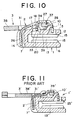
- a slider shown in FIG. 11 has been known.
- the slider is comprised of a body 1', a sheet-like spring 2' and a pull 3'.
- the body 1' one-side ends of an upper wing plate and a lower wing plate, which are disposed in parallel, are connected by a guide post 7' so as to form an element guide groove 13' between the both wing plates.
- the aforementioned sheet-like spring 2' is mounted on a top face of the upper wing plate and is provided at one end thereof with a locking pawl 25', which is adapted to project into the element guide groove 13' through a pawl hole formed in the upper wing plate while it is provided at the other end with a spring portion which is adapted to be fixed in an accommodation groove formed at a front face of the guide post 7'.
- the pull 3' is provided at one end thereof with a grip portion 38' which can be gripped with fingers while it is provided at the other end with an axle having a cam 39' disposed between the body 1' and the sheet-like spring 2'.
- Elastic force is always applied to the axle of the pull 3', thereby making it possible to keep the pull 3' laid. Further, when the pull 3' is raised to rotate the axle, the axle deforms the sheet-like spring 2' elastically and pushes it up, so that the locking pawl 25' can be retracted from the element guide groove 13'.
- the above-described slider for the slide fastener having the locking device is mounted on a slide fastener sewed to trousers or skirt made of jeans.
- the jeans fabric is hard and , mechanical impact is applied to the clothes so as to improve its flexibility, feeling to the touch or the like, in order to overcome such a problem that the clothes made of jeans fabric gives an uncomfortable feeling to a wearer as it is.
- a so-called stone wash operation is carried out, in which a stone of an appropriate size is thrown into a rotation drum together with the clothes to which the aforementioned slide fastener is sewed and then the clothes is struck by the stone when the rotation drum is rotated, or in which the clothes is thrown into a rotation drum provided with a multiplicity of protrusions on an inner periphery thereof and then the clothes is struck by the protrusions in accordance with the rotation of the rotation drum.
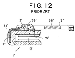
- the pull 3' is laid to the side of a front end of the body 1' so that most part of the pull 3' is protruded from the front end of the body 1' as shown in FIG. 11. If mechanical impact is applied under this condition, a load is applied to the pull 3' in a horizontal direction, namely a direction of pressing the pull 3' toward the axle, or in a vertical direction, namely a direction of pressing down the grip portion 38' of the pull 3'.
- the present invention has been achieved in views of the above-described problems and a point of the present invention is to improve a sheet-like spring so as not to induce plastic deformation.
- plastic deformation of the sheet-like spring is prevented even if a load is applied to the pull in a horizontal direction or a vertical direction when the pull is laid to the side of a front end of a body of the.
- the slider is free from being damaged so that it can exert its locking function accurately for a long period.
- the present invention provides the slider for slide fastener with locking device with a simple structure and an excellent function.
- the slider with locking device having a locking mechanism in which the sheet-like spring comprises a bent portion bent in the same direction as a locking pawl, even if a load in the horizontal direction or in the vertical direction is applied to the pull when the pull is laid to the side of the front end of the body, no plastic deformation is induced in the bent portion of the sheet-like spring, so that it is capable of exerting its locking function accurately. Further, because the bent portion is capable of being elastically deformed sufficiently when the load is applied, it is possible to provide a slider for slide fastener with locking device in which its locking device is free from being damaged for a long period.
- the pull is formed in an appropriate shape for protecting the sheet-like spring having the locking pawl from being plastically deformed, an excellent locking function can be exerted for a long period.
- the sheet-like spring can be prevented securely from being plastically deformed.
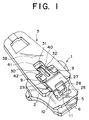
- FIG. 1 is a perspective view of a slider for slide fastener with locking device.
- FIG. 2 is a front view showing a state in which a pull of the slider is laid backward.
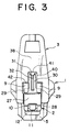
- FIG. 3 is a front view showing a state in which the pull of the slider is laid forward.
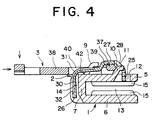
- FIG. 4 is a longitudinal sectional view showing a state in which the pull of the slider is laid forward and the load is applied.
- FIG. 5 is a front view of a modified example of the slider with locking device having a pull showing a state in which the pull is laid backward.
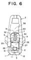
- FIG. 6 is a front view showing a state in which the pull of the modified example is laid forward.
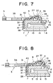
- FIG. 7 is a longitudinal sectional view showing a state in which the pull of the modified example is laid forward.
- FIG. 8 is a longitudinal sectional view showing a state in which the pull of the modified example is laid forward and the load is applied.
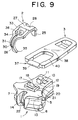
- FIG. 9 is an exploded perspective view of a slider for slide fastener with locking device according to another embodiment.
- FIG. 10 is a longitudinal sectional view showing a state in which the pull of the slider is laid backward.
- FIG. 11 is a longitudinal sectional view showing a state in which a pull of a conventional slider with locking device is laid forward.
- FIG. 12 is a longitudinal sectional view showing a state in which a spring of the slider is deformed plastically.
- the slider for slide fastener with locking device of the present invention is an ordinary type slider having a locking mechanism as shown in FIGS. 1 to 4 and is a sturdy one to be used for jeans.
- the slider is comprised of three members, namely a body 1, a sheet-like spring 2 and a pull 3, and these respective members are manufactured by processing metal such as copper-zinc alloy with pressing means.
- the body 1 of the slider is formed of an upper wing plate 5, a lower wing plate 6 and a guide post 7 for connecting the upper wing plate 5 and the lower wing plate 6.
- a pair of hook-like spring-receiving portions 9, which are laterally arranged, are provided so as to protrude near a shoulder or a front end of the upper wing plate 5 in order to support protruded portions 29 of the sheet-like spring 2.
- a guide portion 10 is provided so as to protrude near a rear opening or a rear end of the upper wing plate 5 such that it is inclined toward the rear opening or the rear end in order to guide an axle 37 of the pull 3.
- a front end of the guide portion 10 is bent toward the rear opening to form an engaging portion 11 for engaging with an engaging hole 28 provided in the sheet-like spring 2.
- a pawl hole 12 is formed at a base portion behind the guide portion 10 for insertion of a locking pawl 25 such that the locking pawl 25 can invade into or retreat from an element guide groove 13 freely.
- an accommodation groove 14 having a V-shaped or U-shaped section is provided at a front face of the guide post 7 such that it can accommodate a drooping portion 26 of a spring portion 30 of the sheet-like spring 2.
- the sheet-like spring 2 is formed in substantially inverted U shape and it has the locking pawl 25 at one end thereof while having a narrow drooping portion 26 at the other end thereof.
- a wide base plate 27 is provided a middle of the sheet-like spring 2.
- the base plate 27 is formed so as to be protruded upward so that the axle 37 having a cam 39 of the pull 3 can be accommodated therein.
- a part extending from the base plate 27 up to the locking pawl 25 is gently bent, where the engaging hole 28, which is capable of loosely engaging with the engaging portion 11 of the guide portion 10 formed on the upper wing plate 5, is provided.
- a front end of the base plate 27 is formed horizontally and both ends thereof are cut out to form protruded portions 29.
- the protruded portions 29 are formed so as to be capable of engaging the spring-receiving portions 9 protruded from the upper wing plate 5.
- the narrow spring portion 30 is extended forward from a middle of the right/left protruded portions 29 provided on the base plate 27 and is bent at a middle portion thereof so as to form a bent portion 31.
- the drooping portion 26 is formed ahead of the bent portion 31 and held in the accommodation groove 14 provided in the guide post 7 of the body 1.
- a dent groove 32 is provided in a center of the spring portion 30 so as to intensify its elasticity.
- the pull 3 is formed of a substantially rectangular plate.
- the axle 37 is provided at an end of the pull 3 while a grip portion 38 is provided at the other end thereof with a gap from the axle 37.
- the cam 39 is formed integrally on a bottom side of the axle 37 such that it is protruded downward.
- a concave portion 41 formed in the center of the through hole 40 such that it is capable of avoiding the bent portion 31 of the sheet-like spring 2 placed on a top face of the guide post 7 of the body 1 when the pull 3 is laid to the side of the front end of the body 1. Further, even when the pull 3 is laid to the side of the front end of the body 1 so that a load in the horizontal direction or the vertical direction is applied to the pull 3, the concave portion 41 does not contact the bent portion 31 of the sheet-like spring 2 and a gap is formed between the grip portion 38 and the bent portion 31.
- extended portions 42 extended on both sides of the concave portion 41 can come into contact with base portions of the spring-receiving portions 9 protruded from the top face of the upper wing plate 5, so as to receive the load applied to the pull 3.
- the axle 37 having the cam 39 of the pull 3 is placed between the spring-receiving portions 9 and the guide portion 10 protruded on the top face of the upper wing plate 5 of the body 1. At this time, the axle 37 is placed such that the cam 39 of the pull 3 is directed downward and the pull 3 is laid toward the rear opening or the rear end of the body 1. Then, the sheet-like spring 2 is disposed on a top face thereof.
- the protruded portions 29 are disposed under the spring-receiving portions 9 such that the base plate 27 of the sheet-like spring 2 covers the axle 37, while the engaging hole 28 in the sheet-like spring 2 holds the engaging portion 11 of the distal end of the guide portion 10 and then, the drooping portion 26 of the spring portion 30 is inserted into the accommodation groove 14 formed at the front face of the guide post 7 of the body 1 and fixed thereto.
- the drooping portion 26 by crimping both sides of the accommodating groove 14 or it is permissible to provide a front end of the drooping portion 26 with protrusions protruded to the both sides and then engage them with concave portions incised in the both sides of the accommodating groove 14.
- the locking pawl 25 of the sheet-like spring 2 fixed to the guide post 7 is always protruded into the element guide groove 13 in the body 1 such that it can invade into or retreat from the element guide groove 13 freely by the operation of the pull 3.
- the assembled slider having the locking mechanism is mounted to a fastener chain. When with the pull 3 laid forward, the slider is pulled, the fastener chain is closed.
- the feature of the slider of the present invention is in solving such a problem that not when the pull 3 is laid to the side of the rear end of the body 1 but when it is laid to the side of the front end of the body 1 as shown in FIG. 4, a load is applied to the pull 3 in the horizontal direction or the vertical direction, and even if the axle 37 of the pull 3 is moved upward toward the guide portion 10 trying to push up the sheet-like spring 2, the expanded portions 42 of the pull 3 come into contact with the base portions of the spring-receiving portions 9 so that the pull 3 cannot be moved further.
- FIGS. 5 to 8 show a modified example of the slider having the locking device in which the shapes of the slider and the pull 3 are different from the above-described slider.
- the configurations of the body 1 and the sheet-like spring 2 are the same.
- the pull 3 is provided with an axle 37 with which a cam 39 eccentric downward is formed integrally, at an end thereof while a grip portion 38 is formed on the other end.
- the through hole 40 is formed such that it is be capable of avoiding the bent portion 31 of the spring portion 30 of the sheet-like spring 2 disposed on the top face of the guide post 7 when the pull 3 is disposed on the body 1 and laid to the side of the front end thereof. There is formed a gap between the grip portion 38 and the bent portion 31 when the pull 3 is disposed on the body 1 and laid to the side of the front end thereof.
- the pull 3 is mounted such that the cam 39 of the pull 3 is placed between the spring-receiving portions 9 and the guide portion 10 in a state that the cam 39 of the pull 3 is directed downward and the pull 3 is laid to the side of the rear end.
- the protruded portions 29 are disposed below the spring-receiving portions 9 such that the base plate 27 of the sheet-like spring 2 covers the axle 37.
- the engaging hole 28 of the sheet-like spring 2 holds the engaging portion 11 of the guide portion 10 and at the same time, the drooping portion 26 of the spring portion 30 is inserted into the accommodation groove 14 formed at the front face of the guide post 7 and fixed thereto.
- the sheet-like spring 2 When the locking pawl 25 is located at its rising limit position, there exists a gap between the grip portion 38 of the pull 3 and the bent portion 31 of the sheet-like spring 2, so that the grip portion 38 never contacts the bent portion 31 to press the bent portion 31, thereby making it possible to block the bent portion 31 from being plastically deformed. Further, when the load applied to the pull 3 is released, the sheet-like spring 2 can be elastically restored to its original state quickly. Namely, the sheet-like spring 2 may be elastically deformed in an effective manner for a long period.
- FIGS. 9 and 10 show another embodiment of a slider with locking device.
- a hook-shaped protruded portion 17 is provided in a center of a shoulder portion or a front end of an upper wing plate 5 of a body 1.
- This protruded portion 17 has an engaging protrusion 18 protruded horizontally from a center of a front end thereof such that it can invade into a hole portion 34 provided in a engaging tongue portion 33 of a sheet-like spring 2.
- Contact portions 19, which can make contact with the engaging tongue piece 33 of the sheet-like spring 2 are formed on both sides of the engaging protrusion 18 at the front end of the protruded portion 17. These contact portions 19 are formed to be vertical planes relative to a top face of the upper wing plate 5.
- a guide portion 10 is provided protrudedly on a center of a rear opening or a rear end of the upper wing plate 5 such that it is inclined backward.
- a front end of the guide portion 10 is bent to form an engaging portion 11, so that it can loosely engage an engaging hole 28 of the sheet-like spring 2.
- a pawl hole 12, which leads to the element guide groove 13, is provided at the base portion of the guide portion 10.
- an accommodation groove 14, which is capable of accommodating a drooping portion 26 of a spring portion 30 of the sheet-like spring 2 is provided at a front face of a guide post 7.
- the sheet-like spring 2 is formed in a substantially inverted U shape and has a locking pawl 25 at one end thereof while it has a narrow drooping portion 26 at the other end thereof.
- the protruded portion 35 is provided at a front end of the drooping portion 26 such that it is protruded to both sides thereof so that it engages the engaging portion 22 of the guide post 7.
- An opening 36 is provided in a central base plate 27 of the sheet-like spring 2.
- the engaging tongue piece 33 is provided such that it is extended forward from the opening edge of the opening 36 and bent downward.
- a hole portion 34 is provided in the center of the holding tongue piece 33 so that the engaging protrusion 18 of the protruded portion 17 is capable of loosely engaging the hole portion 34.
- An engaging hole 28 is provided near the locking pawl 25 of the sheet-like spring 2 so that the engaging portion 11 of the guide portion 10 located at the rear end is capable of loosely engaging the engaging hole 28, thereby restricting the locking pawl 25 from being raised.
- the pull 3 has an axle 37 at one end thereof while it has a grip portion 38 at the other end.
- a through hole 40 is provided between the axle 37 and the grip portion 38 such that its edge at the side of the grip portion 38 is circular.
- the through hole 40 is formed such that it can avoid the bent portion 31 of the spring portion 30 of the sheet-like spring 2 placed on a top face of the guide post 7 when the pull 3 disposed on the body 1 is laid to the side of the front end. Consequently, there always exists a gap between the grip portion 38 and the bent portion 31 so as not to block the motion of the spring portion 30.
- the pull 3 is mounted such that the cam 39 of the pull 3 is placed between the spring-receiving portions 9 and the guide portion 10 in a state that the cam 39 of the pull 3 is directed downward and the pull 3 is laid to the side of the rear end.
- the sheet-like spring 2 is mounted on a top face of the pull 3.
- the locking pawl 25 is inserted into the pawl hole 12 in the upper wing plate 5 as shown in FIG. 10, while the engaging hole 28 loosely engages the guide portion 10, so that an opening edge of the engaging hole 28 can be held by the engaging portion 11.
- the protruded portion 17 is inserted into the opening 36 provided in front of the base plate 27 of the sheet-like spring 2 and at the same time, the engaging tongue piece 33 is inserted into the through hole 20 provided under the protruded portion 17, such that the engaging protrusion 18 existing in the center of the front end of the protruded portion 17 engages the hole portion 34 of the engaging tongue piece 33.
- the side edges of the sheet-like spring 2 are mounted on the supporting base 21 provided on the upper wing plate 5 so that the surface of the engaging tongue piece 33 is pressed against the contact portion 19 provided on the protruded portion 17.
- the protruded portion 35 provided at both sides of the front end of the drooping portion 26 of the spring portion 30 provided on a front end of the sheet-like spring 2 is pressed down along the slopes on both sides of the accommodating groove 14 provided in the guide post 7 so that the protruded portion 35 engage the engaging portions 22 to be fixed thereto.
- the slider can be assembled.
- the pull has an axle with an eccentric cam formed integrally, it is permissible to employ such a pull in which an axle thereof is disposed in the same plane as the grip portion.
- the slider with a locking device comprised of a body 1 with an element guide groove 13, which is formed by connecting an upper wing plate 5 having a pawl hole 12 with a lower wing plate 6 via a guide post 7, a sheet-like spring 2 mounted on the upper wing plate 5 and having a bending locking pawl 25 at one end thereof, and a pull 3 having a grip portion 38 at one end thereof and an axle 37 having a cam 39 at the other end such that the axle 37 is disposed between the upper wing plate 5 and the sheet-like spring 2, wherein when the pull 3 pivoted on the upper wing plate 5 is laid forward of the slider body 1 and a pressure is applied, there exists a gap between the sheet-like spring 2 exposed at the guide post 7 and the grip portion 38.
- the sheet-like spring 2 has a bent portion 31 of a spring portion 30 bent in the same direction as the locking pawl 25, at an exposed part of the guide post 7. Therefore, the exposed part of the guide post 7 is the bent portion 31 of the sheet-like spring 2.
- the bent portion 31 in which the elastic deformation occurs most excessively in the sheet-like spring 2 can be protected so that the sheet-like spring 2 can be allowed to be elastically deformed effectively for a long period.
- the gap existing between the bent portion 31 and the guide post 7 allows the bent portion 31 to keep its elastic deformation with a sufficient room.
- the pull 3 has an inverted-T shaped through hole 40 in which its side toward the axle 37 is expanded, a dented portion 41 of the through hole 40 avoids the sheet-like spring 2 when the pull 3 is laid forward and a pressure is applied, and an expanded portion 42 is capable of making contact with a spring-receiving portions 9 provided on a top face of the body 1, the through hole 40 is capable of avoiding the bent portion 31 of the sheet-like spring 2 effectively. Additionally, because the expanded portion 42 makes contact with the spring-receiving portion 9, even if an excessive load is applied to the pull 3, the elasticity of the sheet-like spring 2 can be protected from any influence.
- the pull 3 has a through hole 40 in which its side toward the grip portion 38 is circular, when the pull 3 is laid forward and a pressure is applied, a circular edge of the through hole 40 avoids the sheet-like spring 2. Consequently, even if the through hole 40 avoids the bent portion 31 so that the pull 3 is deviated slightly to the right or the left for example, the bent portion 31 of the sheet-like spring 2 is protected from any influence.
- the sheet-like spring 2 has an engaging hole 28 for engaging with a guide portion 10 provided so as to be inclined on a top face of the body 1 above the locking pawl 25, and when the pull 3 is laid forward and a pressure is applied, the engaging hole 28 engage an engaging portion 11 bent at a front end of the guide portion 10, thereby blocking the locking pawl 25 from being raised. Consequently, even if a load is applied to the pull 3 in the horizontal direction or the vertical direction, so that the axle 37 of the pull 3 raises the sheet-like spring 2 up to the rising limit position of the locking pawl 25, the grip portion 38 of the pull 3 never contacts the bent portion 31 to apply a pressure. Therefore, an effective locking function is ensured for a long period. Thus, the effects which the present invention achieves are very remarkable.
Landscapes
- Slide Fasteners (AREA)
- Clamps And Clips (AREA)
- Portable Nailing Machines And Staplers (AREA)
- Buckles (AREA)
Abstract
Description
- 1:
- Body
- 2:
- Sheet-like spring
- 3:
- Pull
- 5:
- Upper wing plate
- 6:
- Lower wing plate
- 7:
- Guide post
- 9:
- Spring-receiving portion
- 10:
- Guide portion
- 12:
- Pawl hole
- 13:
- Element guide groove
- 25:
- Locking pawl
- 28:
- Engaging hole
- 30:
- Spring portion
- 31:
- Bent portion
- 37:
- Axle
- 38:
- Grip portion
- 39:
- Cam
- 40:
- Through hole
- 41:
- Concave portion
- 42:
- Expanded portion
Claims (6)
- A slider for slide fastener with locking device comprised of a body (1) with an element guide groove (13), which is formed by connecting an upper wing plate (5) having a pawl hole (12) with a lower wing plate (6) via a guide post (7), a sheet-like spring (2) mounted on the upper wing plate (5) and having a bending locking pawl (25) at one end thereof, and a pull (3) having a grip portion (38) at one end thereof and an axle (37) having a cam (39) at the other end such that the axle (37) is disposed between the upper wing plate (5) and the sheet-like spring (2),
being characterized in that when the pull (3) pivoted on the upper wing plate (5) is laid forward of the slider body (1), there exists a gap between the sheet-like spring (2) exposed at the guide post (7) and the grip portion (38). - A slider for slide fastener with locking device according to claim 1, being characterized in that said sheet-like spring (2) has a bent portion (31) of a spring portion (30) bent in the same direction as the locking pawl (25), at an exposed part of the guide post (7).
- A slider for slide fastener with locking device according to claim 2, being characterized in that a gap is provided between the bent portion (31) and the guide post (7) so that the sheet-like spring (2) is allowed to be elastically deformed.
- A slider for slide fastener with locking device according to claim 1. being characterized in that the pull (3) has an inverted-T shaped through hole (40) in which its side toward the axle (37) is expanded, a dented portion (41) of the through hole (40) avoids the sheet-like spring (2) when the pull (3) is laid forward and a pressure is applied, and an expanded portion (42) is capable of making contact with a spring-receiving portions (9) provided on a top face of the body (1).
- A slider for slide fastener with locking device according to claim 1, being characterized in that the pull (3) has a through hole (40) in which its side toward the grip portion (38) is circular and when the pull (3) is laid forward and a pressure is applied, a circular edge of the through hole (40) avoids the sheet-like spring (2).
- A slider for slide fastener with locking device according to claim 1, being characterized in that the sheet-like spring (2) has an engaging hole (28) for engaging with a guide portion (10) provided so as to be inclined on a top face of the body (1) above the locking pawl (25), and when the pull (3) is laid forward and a pressure is applied, the engaging hole (28) engage an engaging portion (11) bent at a front end of the guide portion (10), thereby blocking the locking pawl (25) from being raised.
Applications Claiming Priority (2)
| Application Number | Priority Date | Filing Date | Title |
|---|---|---|---|
| JP2001124626A JP3714534B2 (en) | 2001-04-23 | 2001-04-23 | Slider for slide fastener with stop device |
| JP2001124626 | 2001-04-23 |
Publications (3)
| Publication Number | Publication Date |
|---|---|
| EP1262115A2 true EP1262115A2 (en) | 2002-12-04 |
| EP1262115A3 EP1262115A3 (en) | 2003-12-17 |
| EP1262115B1 EP1262115B1 (en) | 2010-10-06 |
Family
ID=18973984
Family Applications (1)
| Application Number | Title | Priority Date | Filing Date |
|---|---|---|---|
| EP02008518A Expired - Lifetime EP1262115B1 (en) | 2001-04-23 | 2002-04-15 | Slider for slide fastener with locking device |
Country Status (9)
| Country | Link |
|---|---|
| US (1) | US6637078B2 (en) |
| EP (1) | EP1262115B1 (en) |
| JP (1) | JP3714534B2 (en) |
| KR (1) | KR100464603B1 (en) |
| CN (1) | CN1268249C (en) |
| DE (1) | DE60237861D1 (en) |
| ES (1) | ES2351185T3 (en) |
| HK (1) | HK1048421B (en) |
| TW (1) | TW576720B (en) |
Cited By (1)
| Publication number | Priority date | Publication date | Assignee | Title |
|---|---|---|---|---|
| US8782857B2 (en) | 2010-09-10 | 2014-07-22 | Ykk Corporation | Slider for slide fastener |
Families Citing this family (32)
| Publication number | Priority date | Publication date | Assignee | Title |
|---|---|---|---|---|
| FI20035128A7 (en) * | 2003-08-01 | 2003-08-15 | Stenhaell Turo | Zipper slider |
| JP4307356B2 (en) * | 2004-10-07 | 2009-08-05 | Ykk株式会社 | Slider for slide fastener with automatic stop device |
| JP2008161246A (en) * | 2006-12-27 | 2008-07-17 | Ykk Corp | Member having springiness and product using the same |
| USD579376S1 (en) * | 2007-06-01 | 2008-10-28 | Ching-Yu Hsiao | Pull tab for slide fastener |
| USD579377S1 (en) * | 2007-06-04 | 2008-10-28 | Ching-Yu Hsiao | Pull tab for slide fastener |
| EP2622984B1 (en) * | 2008-04-23 | 2015-03-04 | YKK Corporation | Slider for a slide fastener |
| CN101986925B (en) * | 2009-08-04 | 2012-07-04 | 福建浔兴拉链科技股份有限公司 | Pull head sliding block and die and method for manufacturing same |
| CN102665474B (en) * | 2009-12-25 | 2015-01-28 | Ykk株式会社 | Slider for slide fastener |
| JP3160840U (en) * | 2010-04-28 | 2010-07-08 | Ykk株式会社 | Slider for slide fastener |
| EP2622983B1 (en) | 2010-09-29 | 2019-03-20 | YKK Corporation | Slider for slide fastener |
| TWM403917U (en) * | 2010-12-17 | 2011-05-21 | Ching-Jen Tsai | Zipper head to assemble easily and to have the positioning function |
| US8567019B2 (en) * | 2011-04-18 | 2013-10-29 | Ykk Corporation Of America | Semi-automatic slider |
| US20120297584A1 (en) * | 2011-05-24 | 2012-11-29 | Chung Chwan Enterprise Co., Ltd. | Zipper head structure |
| US9271548B2 (en) * | 2011-06-17 | 2016-03-01 | Ykk Corporation | Slider for slider fasteners |
| CN102641022B (en) * | 2012-04-21 | 2014-12-17 | 开易(浙江)服装配件有限公司 | Zipper slider with demountable pull tab |
| JP6031531B2 (en) * | 2012-11-09 | 2016-11-24 | Ykk株式会社 | Slider for slide fastener |
| WO2015004763A1 (en) | 2013-07-11 | 2015-01-15 | Ykk株式会社 | Slide fastener slider |
| WO2015063937A1 (en) * | 2013-10-31 | 2015-05-07 | Ykk株式会社 | Slider |
| GB2528229B (en) * | 2014-03-28 | 2020-05-13 | Ykk Corp | Slider for a slide fastener |
| GB201405748D0 (en) * | 2014-03-31 | 2014-05-14 | Coats Ltd J & P | Zip slider |
| US10064456B2 (en) * | 2015-07-03 | 2018-09-04 | Chung Chwan Enterprise Co., Ltd. | Zip slider structure |
| TWM512945U (en) * | 2015-07-03 | 2015-12-01 | Lung Chou Ind Co Ltd | Zipper head structure |
| USD804988S1 (en) * | 2016-08-31 | 2017-12-12 | Ideal Fastener (Guangdong) Industries Ltd. | Slider |
| CN106388143B (en) * | 2016-11-14 | 2023-03-24 | 理想(广东)拉链实业有限公司 | Spring pull head |
| TWI679948B (en) * | 2017-08-07 | 2019-12-21 | 中傳企業股份有限公司 | Zipper head assembly structure and elastic element thereof |
| CN107802062A (en) * | 2017-11-27 | 2018-03-16 | 福建浔兴拉链科技股份有限公司 | A kind of structure is improved to exempt from riveted copper pull head |
| CN107772663A (en) * | 2017-11-30 | 2018-03-09 | 福建浔兴拉链科技股份有限公司 | A kind of copper pull head with double jump point |
| TWI646915B (en) * | 2018-01-08 | 2019-01-11 | 中傳企業股份有限公司 | Zipper head combination structure and elastic member |
| CN108720186A (en) * | 2018-07-18 | 2018-11-02 | 广东海华拉链有限公司 | Nylon zipper pull head |
| US11241047B1 (en) * | 2021-03-03 | 2022-02-08 | Caitlin Hurst | Locking zipper and garments associated therewith |
| US12685370B2 (en) * | 2022-02-16 | 2026-07-21 | Ykk Corporation | Slider for slide fastener and slide fastener including the same |
| CN119279317A (en) * | 2023-07-10 | 2025-01-10 | Ykk株式会社 | Slider |
Family Cites Families (7)
| Publication number | Priority date | Publication date | Assignee | Title |
|---|---|---|---|---|
| GB821650A (en) * | 1955-09-19 | 1959-10-14 | Talon Inc | Improvements in or relating to automatic lock slider for slide fastenings |
| US3320645A (en) * | 1966-01-06 | 1967-05-23 | Scovill Manufacturing Co | Lock slider for zipper fasteners |
| US4074399A (en) * | 1976-11-08 | 1978-02-21 | Textron, Inc. | Slider for slide fastener |
| US4644613A (en) * | 1985-10-21 | 1987-02-24 | Talon, Inc. | Locking slider for slide fastener |
| JPH0757204B2 (en) * | 1986-07-04 | 1995-06-21 | ワイケイケイ株式会社 | Slide fastener with slider with stop device |
| JPH0721123Y2 (en) * | 1988-10-22 | 1995-05-17 | ワイケイケイ株式会社 | Slider for slide fastener with automatic stop device |
| JP3369059B2 (en) * | 1996-09-30 | 2003-01-20 | ワイケイケイ株式会社 | Slider for slide fastener with automatic stop device |
-
2001
- 2001-04-23 JP JP2001124626A patent/JP3714534B2/en not_active Expired - Fee Related
-
2002
- 2002-04-11 US US10/119,834 patent/US6637078B2/en not_active Expired - Lifetime
- 2002-04-15 ES ES02008518T patent/ES2351185T3/en not_active Expired - Lifetime
- 2002-04-15 DE DE60237861T patent/DE60237861D1/en not_active Expired - Lifetime
- 2002-04-15 EP EP02008518A patent/EP1262115B1/en not_active Expired - Lifetime
- 2002-04-17 TW TW091107875A patent/TW576720B/en not_active IP Right Cessation
- 2002-04-22 KR KR10-2002-0021934A patent/KR100464603B1/en not_active Expired - Lifetime
- 2002-04-23 CN CNB021180997A patent/CN1268249C/en not_active Expired - Lifetime
-
2003
- 2003-01-23 HK HK03100605.4A patent/HK1048421B/en not_active IP Right Cessation
Cited By (1)
| Publication number | Priority date | Publication date | Assignee | Title |
|---|---|---|---|---|
| US8782857B2 (en) | 2010-09-10 | 2014-07-22 | Ykk Corporation | Slider for slide fastener |
Also Published As
| Publication number | Publication date |
|---|---|
| EP1262115B1 (en) | 2010-10-06 |
| CN1382406A (en) | 2002-12-04 |
| JP2002315609A (en) | 2002-10-29 |
| KR20020082146A (en) | 2002-10-30 |
| ES2351185T3 (en) | 2011-02-01 |
| KR100464603B1 (en) | 2005-01-03 |
| JP3714534B2 (en) | 2005-11-09 |
| HK1048421A1 (en) | 2003-04-04 |
| CN1268249C (en) | 2006-08-09 |
| HK1048421B (en) | 2007-01-05 |
| US20020152591A1 (en) | 2002-10-24 |
| DE60237861D1 (en) | 2010-11-18 |
| EP1262115A3 (en) | 2003-12-17 |
| US6637078B2 (en) | 2003-10-28 |
| TW576720B (en) | 2004-02-21 |
Similar Documents
| Publication | Publication Date | Title |
|---|---|---|
| US6637078B2 (en) | Slider for slide fastener with locking device | |
| JP3240559B2 (en) | Buckle assembly | |
| CN1082358C (en) | Auto-lock slider for concealed slide fastener | |
| US5485659A (en) | Buckle for watch bands | |
| US4005510A (en) | Plastic clip | |
| KR900007522Y1 (en) | Buckle assembly | |
| JPH0424625Y2 (en) | ||
| KR100380249B1 (en) | Method of operating plastic clip, and plastic clip using same method | |
| CN113163904B (en) | Plug for buckle and buckle | |
| JPS6345201B2 (en) | ||
| US5355899A (en) | Arched hairclip | |
| NL8503343A (en) | FASTENING HANDLE WITH BELT AND SEAT BELT. | |
| KR880000143B1 (en) | Slide fastener | |
| US7219401B2 (en) | Slider for slide fastener with automatic stopper | |
| EP0311042B1 (en) | Buckle assembly | |
| US3993009A (en) | Presser foot sewing machines | |
| US20030123689A1 (en) | Microphone holder | |
| KR200438450Y1 (en) | Buckle of Industrial Seat Belt | |
| CN101282666A (en) | Pin holder type retainer | |
| US3030970A (en) | Pivoted spring clamp | |
| KR910005457Y1 (en) | buckle | |
| US2709358A (en) | Key hanger support for key cases | |
| JPH068724Y2 (en) | Hook metal | |
| JP2503686Y2 (en) | Grasping part locking structure | |
| JP3213807B2 (en) | Card connector |
Legal Events
| Date | Code | Title | Description |
|---|---|---|---|
| PUAI | Public reference made under article 153(3) epc to a published international application that has entered the european phase |
Free format text: ORIGINAL CODE: 0009012 |
|
| AK | Designated contracting states |
Kind code of ref document: A2 Designated state(s): AT BE CH CY DE DK ES FI FR GB GR IE IT LI LU MC NL PT SE TR |
|
| AX | Request for extension of the european patent |
Free format text: AL;LT;LV;MK;RO;SI |
|
| PUAL | Search report despatched |
Free format text: ORIGINAL CODE: 0009013 |
|
| AK | Designated contracting states |
Kind code of ref document: A3 Designated state(s): AT BE CH CY DE DK ES FI FR GB GR IE IT LI LU MC NL PT SE TR |
|
| AX | Request for extension of the european patent |
Extension state: AL LT LV MK RO SI |
|
| 17P | Request for examination filed |
Effective date: 20040609 |
|
| AKX | Designation fees paid |
Designated state(s): DE ES FR GB IT |
|
| 17Q | First examination report despatched |
Effective date: 20050506 |
|
| 17Q | First examination report despatched |
Effective date: 20050506 |
|
| GRAP | Despatch of communication of intention to grant a patent |
Free format text: ORIGINAL CODE: EPIDOSNIGR1 |
|
| GRAS | Grant fee paid |
Free format text: ORIGINAL CODE: EPIDOSNIGR3 |
|
| GRAA | (expected) grant |
Free format text: ORIGINAL CODE: 0009210 |
|
| AK | Designated contracting states |
Kind code of ref document: B1 Designated state(s): DE ES FR GB IT |
|
| REG | Reference to a national code |
Ref country code: GB Ref legal event code: FG4D |
|
| REF | Corresponds to: |
Ref document number: 60237861 Country of ref document: DE Date of ref document: 20101118 Kind code of ref document: P |
|
| REG | Reference to a national code |
Ref country code: ES Ref legal event code: FG2A Effective date: 20110120 |
|
| PLBE | No opposition filed within time limit |
Free format text: ORIGINAL CODE: 0009261 |
|
| STAA | Information on the status of an ep patent application or granted ep patent |
Free format text: STATUS: NO OPPOSITION FILED WITHIN TIME LIMIT |
|
| 26N | No opposition filed |
Effective date: 20110707 |
|
| REG | Reference to a national code |
Ref country code: DE Ref legal event code: R097 Ref document number: 60237861 Country of ref document: DE Effective date: 20110707 |
|
| REG | Reference to a national code |
Ref country code: FR Ref legal event code: PLFP Year of fee payment: 15 |
|
| REG | Reference to a national code |
Ref country code: FR Ref legal event code: PLFP Year of fee payment: 16 |
|
| REG | Reference to a national code |
Ref country code: FR Ref legal event code: PLFP Year of fee payment: 17 |
|
| PGFP | Annual fee paid to national office [announced via postgrant information from national office to epo] |
Ref country code: FR Payment date: 20200312 Year of fee payment: 19 |
|
| PGFP | Annual fee paid to national office [announced via postgrant information from national office to epo] |
Ref country code: ES Payment date: 20200504 Year of fee payment: 19 |
|
| PGFP | Annual fee paid to national office [announced via postgrant information from national office to epo] |
Ref country code: GB Payment date: 20200408 Year of fee payment: 19 Ref country code: IT Payment date: 20200312 Year of fee payment: 19 |
|
| PGFP | Annual fee paid to national office [announced via postgrant information from national office to epo] |
Ref country code: DE Payment date: 20210316 Year of fee payment: 20 |
|
| GBPC | Gb: european patent ceased through non-payment of renewal fee |
Effective date: 20210415 |
|
| PG25 | Lapsed in a contracting state [announced via postgrant information from national office to epo] |
Ref country code: GB Free format text: LAPSE BECAUSE OF NON-PAYMENT OF DUE FEES Effective date: 20210415 Ref country code: FR Free format text: LAPSE BECAUSE OF NON-PAYMENT OF DUE FEES Effective date: 20210430 |
|
| REG | Reference to a national code |
Ref country code: DE Ref legal event code: R071 Ref document number: 60237861 Country of ref document: DE |
|
| REG | Reference to a national code |
Ref country code: ES Ref legal event code: FD2A Effective date: 20220701 |
|
| PG25 | Lapsed in a contracting state [announced via postgrant information from national office to epo] |
Ref country code: ES Free format text: LAPSE BECAUSE OF NON-PAYMENT OF DUE FEES Effective date: 20210416 |
|
| PG25 | Lapsed in a contracting state [announced via postgrant information from national office to epo] |
Ref country code: IT Free format text: LAPSE BECAUSE OF NON-PAYMENT OF DUE FEES Effective date: 20200415 |
|
| PG25 | Lapsed in a contracting state [announced via postgrant information from national office to epo] |
Ref country code: IT Free format text: LAPSE BECAUSE OF NON-PAYMENT OF DUE FEES Effective date: 20210415 |