EP1261674B1 - Stretch releasing adhesive tape with differential adhesive properties - Google Patents
Stretch releasing adhesive tape with differential adhesive properties Download PDFInfo
- Publication number
- EP1261674B1 EP1261674B1 EP00989395A EP00989395A EP1261674B1 EP 1261674 B1 EP1261674 B1 EP 1261674B1 EP 00989395 A EP00989395 A EP 00989395A EP 00989395 A EP00989395 A EP 00989395A EP 1261674 B1 EP1261674 B1 EP 1261674B1
- Authority
- EP
- European Patent Office
- Prior art keywords
- adhesive tape
- stretch releasing
- surface area
- releasing adhesive
- article
- Prior art date
- Legal status (The legal status is an assumption and is not a legal conclusion. Google has not performed a legal analysis and makes no representation as to the accuracy of the status listed.)
- Expired - Lifetime
Links
Images


Classifications
-
- C—CHEMISTRY; METALLURGY
- C09—DYES; PAINTS; POLISHES; NATURAL RESINS; ADHESIVES; COMPOSITIONS NOT OTHERWISE PROVIDED FOR; APPLICATIONS OF MATERIALS NOT OTHERWISE PROVIDED FOR
- C09J—ADHESIVES; NON-MECHANICAL ASPECTS OF ADHESIVE PROCESSES IN GENERAL; ADHESIVE PROCESSES NOT PROVIDED FOR ELSEWHERE; USE OF MATERIALS AS ADHESIVES
- C09J7/00—Adhesives in the form of films or foils
- C09J7/20—Adhesives in the form of films or foils characterised by their carriers
-
- C—CHEMISTRY; METALLURGY
- C09—DYES; PAINTS; POLISHES; NATURAL RESINS; ADHESIVES; COMPOSITIONS NOT OTHERWISE PROVIDED FOR; APPLICATIONS OF MATERIALS NOT OTHERWISE PROVIDED FOR
- C09J—ADHESIVES; NON-MECHANICAL ASPECTS OF ADHESIVE PROCESSES IN GENERAL; ADHESIVE PROCESSES NOT PROVIDED FOR ELSEWHERE; USE OF MATERIALS AS ADHESIVES
- C09J7/00—Adhesives in the form of films or foils
- C09J7/10—Adhesives in the form of films or foils without carriers
-
- C—CHEMISTRY; METALLURGY
- C09—DYES; PAINTS; POLISHES; NATURAL RESINS; ADHESIVES; COMPOSITIONS NOT OTHERWISE PROVIDED FOR; APPLICATIONS OF MATERIALS NOT OTHERWISE PROVIDED FOR
- C09J—ADHESIVES; NON-MECHANICAL ASPECTS OF ADHESIVE PROCESSES IN GENERAL; ADHESIVE PROCESSES NOT PROVIDED FOR ELSEWHERE; USE OF MATERIALS AS ADHESIVES
- C09J2301/00—Additional features of adhesives in the form of films or foils
- C09J2301/20—Additional features of adhesives in the form of films or foils characterized by the structural features of the adhesive itself
- C09J2301/204—Additional features of adhesives in the form of films or foils characterized by the structural features of the adhesive itself the adhesive coating being discontinuous
-
- C—CHEMISTRY; METALLURGY
- C09—DYES; PAINTS; POLISHES; NATURAL RESINS; ADHESIVES; COMPOSITIONS NOT OTHERWISE PROVIDED FOR; APPLICATIONS OF MATERIALS NOT OTHERWISE PROVIDED FOR
- C09J—ADHESIVES; NON-MECHANICAL ASPECTS OF ADHESIVE PROCESSES IN GENERAL; ADHESIVE PROCESSES NOT PROVIDED FOR ELSEWHERE; USE OF MATERIALS AS ADHESIVES
- C09J2301/00—Additional features of adhesives in the form of films or foils
- C09J2301/30—Additional features of adhesives in the form of films or foils characterized by the chemical, physicochemical or physical properties of the adhesive or the carrier
- C09J2301/308—Additional features of adhesives in the form of films or foils characterized by the chemical, physicochemical or physical properties of the adhesive or the carrier the adhesive tape or sheet losing adhesive strength when being stretched, e.g. stretch adhesive
-
- Y—GENERAL TAGGING OF NEW TECHNOLOGICAL DEVELOPMENTS; GENERAL TAGGING OF CROSS-SECTIONAL TECHNOLOGIES SPANNING OVER SEVERAL SECTIONS OF THE IPC; TECHNICAL SUBJECTS COVERED BY FORMER USPC CROSS-REFERENCE ART COLLECTIONS [XRACs] AND DIGESTS
- Y10—TECHNICAL SUBJECTS COVERED BY FORMER USPC
- Y10T—TECHNICAL SUBJECTS COVERED BY FORMER US CLASSIFICATION
- Y10T428/00—Stock material or miscellaneous articles
- Y10T428/24—Structurally defined web or sheet [e.g., overall dimension, etc.]
- Y10T428/24942—Structurally defined web or sheet [e.g., overall dimension, etc.] including components having same physical characteristic in differing degree
- Y10T428/2495—Thickness [relative or absolute]
-
- Y—GENERAL TAGGING OF NEW TECHNOLOGICAL DEVELOPMENTS; GENERAL TAGGING OF CROSS-SECTIONAL TECHNOLOGIES SPANNING OVER SEVERAL SECTIONS OF THE IPC; TECHNICAL SUBJECTS COVERED BY FORMER USPC CROSS-REFERENCE ART COLLECTIONS [XRACs] AND DIGESTS
- Y10—TECHNICAL SUBJECTS COVERED BY FORMER USPC
- Y10T—TECHNICAL SUBJECTS COVERED BY FORMER US CLASSIFICATION
- Y10T428/00—Stock material or miscellaneous articles
- Y10T428/249921—Web or sheet containing structurally defined element or component
- Y10T428/249953—Composite having voids in a component [e.g., porous, cellular, etc.]
- Y10T428/249982—With component specified as adhesive or bonding agent
- Y10T428/249983—As outermost component
-
- Y—GENERAL TAGGING OF NEW TECHNOLOGICAL DEVELOPMENTS; GENERAL TAGGING OF CROSS-SECTIONAL TECHNOLOGIES SPANNING OVER SEVERAL SECTIONS OF THE IPC; TECHNICAL SUBJECTS COVERED BY FORMER USPC CROSS-REFERENCE ART COLLECTIONS [XRACs] AND DIGESTS
- Y10—TECHNICAL SUBJECTS COVERED BY FORMER USPC
- Y10T—TECHNICAL SUBJECTS COVERED BY FORMER US CLASSIFICATION
- Y10T428/00—Stock material or miscellaneous articles
- Y10T428/28—Web or sheet containing structurally defined element or component and having an adhesive outermost layer
- Y10T428/2848—Three or more layers
-
- Y—GENERAL TAGGING OF NEW TECHNOLOGICAL DEVELOPMENTS; GENERAL TAGGING OF CROSS-SECTIONAL TECHNOLOGIES SPANNING OVER SEVERAL SECTIONS OF THE IPC; TECHNICAL SUBJECTS COVERED BY FORMER USPC CROSS-REFERENCE ART COLLECTIONS [XRACs] AND DIGESTS
- Y10—TECHNICAL SUBJECTS COVERED BY FORMER USPC
- Y10T—TECHNICAL SUBJECTS COVERED BY FORMER US CLASSIFICATION
- Y10T428/00—Stock material or miscellaneous articles
- Y10T428/28—Web or sheet containing structurally defined element or component and having an adhesive outermost layer
- Y10T428/2852—Adhesive compositions
- Y10T428/2861—Adhesive compositions having readily strippable combined with readily readhearable properties [e.g., stick-ons, etc.]
Definitions
- the present invention relates generally to an elongated stretch releasing adhesive tape article with a geometry that provides differential adhesive properties, and in particular, to a geometry that provides regions of reduced adhesion to form pull-tabs.
- Stretch releasing adhesive tapes represent an emerging class of high performance pressure-sensitive adhesives combining strong holding power with clean removal and no surface damage, Such stretch releasing adhesive tapes are useful in a wide variety of assembling, joining, attaching, and mounting applications.
- Adhesive tape strips that can be cleanly removed from a surface by stretching the tape strip are known in the prior art.
- U.S. -A-4,024,312 discloses a highly conformable adhesive tape including a highly extensible and elastic backing film laminated with an adhesive layer. The backing film possesses a lengthwise elongation at break of at least about 200%. The tape is easily stretchable and may be removed from a surface by stretching the tape lengthwise in a direction substantially parallel to the surface.
- DE-A- 33 31 016 discloses a high elasticity, low plasticity adhesive film based on a thermoplastic rubber and tackifying resins, wherein the adhesive bond can be broken by stretching the adhesive film in the direction of the plane of the adhesive bond.
- U.S. -A- 5,516,581 assigned to the same assignee as the present invention, discloses a removable adhesive tape having a highly extensible and substantially inelastic backing coated with a layer of pressure sensitive adhesive.
- the adhesive tape can be removed from a substrate without damaging the substrate by stretching the tape in a direction substantially parallel to the surface of the substrate.
- the tape backing has a lengthwise elongation at break of from about 150% to about 1200%, a Young's modulus of at least about 17.2MPa to about 500M Pa (about 2.500 psi to about 72.500 psi) and an elastic recovery of less than about 50% after being stretched and removed.
- WO-A-95/06691 discloses a removable foam adhesive tape comprising a backing including a layer of polymeric foam, and a layer of pressure-sensitive adhesive coated on at least one surface of the backing.
- the foam layer of the backing has a thickness of about 0.76mm to about 2.54cm (about 30 to about 1000 mils) and the backing has a lengthwise elongation at break of from about 50% to about 1200%, and a Young's modulus of less than about 16.5 ⁇ M Pa (about 2,400 psi).
- US-A-5,650,215 discloses a pressure-sensitive adhesive coated article including a tape or a transfer coating, having a microstructured surface, wherein the performance properties of the pressure-sensitive adhesive article can be tailored by independently varying the microstructure and the rheological properties of the pressure-sensitive adhesive.
- Desirable for certain applications is an elongated stretch releasing adhesive tape strip of indefinite length which can be formed into a roll or stack from which segments of selected length can be cut depending on the end use application.
- the difficulty with providing a long length of stretch releasing tape which can be cut to a selected length is the ability to provide a pull tab at a specific location on the cut strip to serve as a grasping area for stretching the strip from a surface at the time of removal.
- WO-A-98/06652 discloses a length cutting fixture that can be used to form a non-adhesive pull tab or "gripper" at the end of a long length of a conventional single-sided adhesive tape.
- the length cutting fixture also serves to cut the long length of tape, now including the gripper, to any selected length.
- the gripper is formed by folding the end of the tape back onto itself.
- Such a length cutting fixture cannot be used to form a non-adhesive pull tab on a double-sided adhesive tape.
- EP-A-0279579 refers to an adhesive sheet with an irregular section adhesion face which leads to easy peelability and re-use.
- the present invention provides a stretch releasing adhesive tape article and methods as defined in the independent claims. Individual embodiments are the subject matter of the dependent claims.
- adhesive tape of the article according to the invention is referred to as stretch releasing adhesive tape although the element need not to be formed as a tape in the sense of e.g. a flak ribbon-like object.
- the present invention relates to various embodiments of a stretch releasing adhesive tape with a geometry that provides differential adhesive properties in a compressed state and an uncompressed state. Adhesion and tack can thus be controlled by varying the amount of compression. Additionally, the present stretch releasing adhesive tape can be easily repositioned prior to compression. A portion of the present stretch releasing adhesive tape can be left in the uncompressed state, thereby providing one or more pull tabs.
- the stretch releasing adhesive tape of the present invention can be provided in strips of varying lengths, in roll form, or in a stack.
- the stretch releasing adhesive tape article includes an elongated length of stretch releasing adhesive tape with side surfaces comprising at least one potential contact surface area. At least a portion of the potential contact surface area comprises an adhesive surface having raised portions.
- the potential contact surface area comprises a first interface surface area in the uncompressed state and a second interface surface area greater than the first interface surface area in the compressed state.
- the stretch releasing adhesive tape in the uncompressed state can operate as a pull tab.
- the stretch releasing adhesive tape article comprises an elongated length of stretch releasing adhesive tape with adhesive on all side surfaces.
- the side surfaces have at least one potential contact surface area.
- the potential contact surface area has a first interface surface area in an uncompressed state and a second interface surface area greater than the first interface surface area in a compressed state.
- the stretch releasing adhesive tape comprises a multi-layered structure.
- the stretch releasing adhesive tape can have one or more elastic or inelastic structural members.
- the structural member can be foam, film, a monofilament or a variety of other materials.
- a film can optionally be interposed between the adhesive and the structural member or located at the interior of the structural member.
- the stretch releasing adhesive tape can be one of a pressure sensitive adhesive tape with an elastic structural member, a pressure sensitive adhesive tape with a highly extensible and substantially inelastic structural member, or a solid pressure sensitive adhesive tape.
- the potential contact surface area in the uncompressed state can be a plurality of raised portions, a non-planar structure, a discontinuous surface, or combinations thereof.
- the stretch releasing adhesive tape in the uncompressed state comprises a cross-section selected from circular, star-shaped, oval, multifaceted or any other geometric shape that provides less surface area in the uncompressed state than in the compressed state.
- the potential contact surface area comprises a rectangular cross-section of stretch releasing adhesive tape twisted to form helical ridges.
- the potential contact surface area can have adhesive regions and non-adhesive regions.
- the elongated length of stretch releasing adhesive tape can be segments or a roll.
- a release liner may optionally be used.
- Frangible connections can be formed intermittently along the stretch releasing adhesive tape.
- the present invention is also direct to a method of using a stretch releasing adhesive tape article with differential adhesive properties, including the steps of positioning a potential contact surface area of an elongated length of stretch releasing adhesive tape on a substrate to form a first interface surface area; compressing a portion of the stretch releasing adhesive tape to form a second interface surface area, the second interface surface area being greater than the first interface surface area; and retaining an uncompressed portion of the stretch releasing adhesive tape as a pull tab.
- the steps include providing an elongated length of stretch releasing adhesive tape with a generally rectangular cross section; twisting at least a portion of the stretch releasing adhesive tape to form a twisted portion with a plurality of helical ridges; positioning the stretch releasing adhesive tape on a substrate, the twisted portion defining a first interface surface area; compressing an untwisted portion of the stretch releasing adhesive tape against the substrate to form a second interface surface area greater than the first interface surface area; and retaining the twisted portion in an uncompressed state to form a pull tab.
- Figure 1 is a front view of an article 20 attached to a substrate 22 using a stretch releasing adhesive tape 24.
- a portion 21 of the stretch releasing adhesive tape 24 is compressed between the article 20 and the substrate 22 to form an adhesive bond.
- the stretch releasing adhesive 24 includes a pull tab 26 that extends beyond the perimeter of the article 20.
- the pull tab 26 typically includes non-adhesive surfaces that prevent bonding with the substrate 22 or the article 20.
- Removing the stretch releasing adhesive tape 24 from the article 20 and substrate 22 can be carried out by simply stretching the stretch releasing adhesive tape 24 in the direction 28 and at an angle of less than about 35 degrees with respect to the substrate 22. Removal at the appropriate angle will result in no appreciable adhesive residue on the substrate 22 and in preventing damage to the substrate 22.
- Figure 2 is a perspective view of a segment of a stretch releasing adhesive tape 30 having a generally rectangular cross section.
- the stretch releasing adhesive tape 30 has a length 32, a width 34, and a thickness 36.
- the stretch releasing adhesive tape 30 has a potential contact surface area 38 and a first interface surface area 40 defined by the length 32 times the width 34.
- potential contact surface area refers to the surface area on a stretch releasing adhesive tape that can potentially contact a planar substrate, whether or not there is adhesive at the interface with the substrate.
- the potential contact surface area can also be understood as the portion of the side surfaces that are illuminate by a light shined perpendicular through transparent substrate 22 onto the stretch releasing adhesive tape.
- the "first interface surface area” refers to the surface area formed at the actual physical interface between the stretch releasing adhesive tape and the substrate 22 in the uncompressed state. Due to the geometry of the stretch releasing adhesive tape 30, the potential contact surface area 38 on the stretch releasing adhesive tape 30 and the first interface surface area 40 with the substrate 22 are substantially the same.
- portion 42 of the stretch releasing adhesive tape 30 is compressed against the substrate 22, while portion 44 remains uncompressed. No pull tab is provided.
- the compressed portion 42 forms a strong adhesive bond with the substrate 22, while the uncompressed portion 44 initially forms less of an adhesive bond. Over time, however, the uncompressed portion 44 will wet-out against the substrate 22 and build adhesion. Consequently, the interface surface area 40 is effectively the same whether all or a portion of the stretch releasing adhesive tape 30 is compressed against the substrate 22.
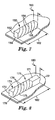
- FIGS 3A and 3B illustrate a stretch releasing adhesive tape 50 with differential adhesive properties in accordance with the present invention.
- Side surfaces 54 of the stretch releasing adhesive tape 50 include a pressure sensitive adhesive.
- the pressure sensitive adhesive can cover some or all of the side surfaces 54.
- the pressure sensitive adhesive can be a continuous or discontinuous region on the side surfaces 54.
- the stretch releasing adhesive tape 50 is a multi-layered structure, including a structural member 51, such as an elastic or inelastic foam, and a film 53 interposed between the structural member 51 and the adhesive layer 55 that defines the side surfaces 54.
- the structural member 51 can be concentric or non-concentric with the adhesive layer 55, hollow or solid, or symmetrical or asymmetrical with the adhesive layer 55.
- Any conventionally known stretch releasing tape can be used in the various embodiments of the present invention, including a pressure sensitive adhesive tape with an elastic core, a pressure sensitive adhesive tape with a highly extensible and substantially inelastic core, or a solid pressure sensitive adhesive.
- a pressure sensitive adhesive tape with an elastic core including a pressure sensitive adhesive tape with a highly extensible and substantially inelastic core, or a solid pressure sensitive adhesive.
- Specific tapes suitable for use in the various embodiments of the present invention include the pressure sensitive adhesive tapes with elastic backings described in U.S. -A- 4,024,312 , the pressure sensitive adhesive tapes with highly extensible and substantially inelastic backings described in U.S. -A-5,516,581 and WO-A-95/0669 , and the solid pressure sensitive adhesive described in DE- C- 33 31 016 .
- the stretch releasing adhesive tape of the present invention can include a splittable layer such as the layers described in WO-A-98/21285 , or a re-fastenable layer such as the layers described in WO-A-99/31193 .
- Figure 3A illustrates the stretch releasing adhesive tape 50 adhered to a substrate 22 in an uncompressed state 52.
- the adhesive side surfaces 54 have a potential contact surface area 56 defined by arc length 60 times length 62.
- the first interface surface area 58 is defined by are length 64 times the length 62.
- the circular cross section of the stretch releasing adhesive 50 causes the first interface surface area 58 with the substrate 22 to be significantly smaller than the potential contact surface area 56.
- Figure 3B illustrates the stretch releasing adhesive tape 50 of Figure 3A in the compressed state 70.
- the potential contact surface area 56 defines a second interface surface area 72 greater than the first interface surface area 58.
- the "second interface surface area” refers to the surface area formed at the actual physical interface between the stretch releasing adhesive tape and the substrate 22 in the compressed state.
- the second interface surface area 72 is defined by the width 71 times the length 62. As illustrated in Figure 3B , the second interface surface area 72 is less than the potential contact surface area 56, although in some embodiments, they can be substantially the same.
- the stretch releasing adhesive tape 50 Due to the increase in surface area, the stretch releasing adhesive tape 50 has greater adhesion with the substrate 22 in the compressed state 70 than in the uncompressed state 52. By selectively leaving portions of the stretch releasing adhesive tape 50 in the uncompressed state, those portions can be later removed from the substrate 22 and used as pull tabs (see Figures 10 and 11 ). Additionally, the first interface surface area 58 can be made sufficiently small that the pressure sensitive adhesive tape 50 can be easily repositioned prior to compression into the compressed state 70.
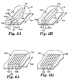
- FIG 4A illustrates an alternate stretch releasing adhesive tape 80 in an uncompressed state 82 in accordance with the present invention.
- the stretch releasing adhesive tape 80 includes a series of raised portions 96A, 96B, 96C, 96D.
- a non-planar adhesive potential contact surface 86 includes raised portions 96C, 96D.
- Raised portions 96C, 96D define a pair of narrow, discrete first interface surface areas 92, 94, respectively, with the substrate 22 in the uncompressed state 82. Rather than the single continuous interface surface area 58 of Figure 3A , the interface surface areas 92, 94 are discrete and discontinuous.
- the level of adhesion generated by the first interface surface areas 92, 94 is sufficiently low that a user can reposition the stretch releasing adhesive tape 80 or detach a portion of the stretch releasing adhesive tape 80 from the substrate 22 and use the detached portion as a pu l 1 tab.
- Figure 4B illustrates the stretch releasing adhesive tape 80 of Figure 4A in a compressed state 84.
- the first interface surface areas 92, 94 are expanded to form the second interface surface area 95 that is defined by the width 97 times the length 99.
- the second interface surface area 95 is substantially the same as the potential contact surface area 86.
- Figures 5A and 5B illustrate a cross sectional view of an alternate stretch releasing adhesive tape 100 in accordance with the present invention.
- Figure 5A illustrates the stretch releasing adhesive tape in the uncompressed state 102.
- the stretch releasing adhesive tape 100 includes a series of raised portions 104A, 104B, 104C, 104D, 104E.
- Potential contact surface area 110 is defined by the segments 105, 107 times the length 109.
- tips of the raised portions 104B, 104C times the length 109 define a pair of discontinuous, non-planar first interface surface areas 106, 108 with the substrate 22.
- the sum of the first interface surface areas 106, 108 is significantly smaller than the potential contact surface area 110. If a portion of the stretch releasing adhesive tape 100 is retained in the uncompressed state 102, that portion can be removed from the substrate 22 and used as a pull tab or repositioned.
- Figure 5B illustrates the stretch releasing adhesive tape 100 of Figure 5A in a compressed state 116.
- Raised portions 104B and 104C have been collapsed against the substrate 22 so that the second interface surface area 118 is the sum of the segments 105, 107 times the length 109, substantially the same as the potential contact surface area 110.
- Figure 6A and 6B illustrate an alternate stretch releasing adhesive tape 130 in accordance with the present invention.
- Figure 6A illustrates the stretch releasing adhesive tape 130 in the uncompressed state 132.
- the stretch releasing adhesive tape 130 includes a series of longitudinal ridges or raised portions 134 that define the first interface surface area 136.
- the raised portions 134 can be formed on one or more surfaces of the stretch releasing adhesive tape 130.
- the first interface surface area 136 is a series of elongated strips that correspond to the tips of the raised portions 134.
- the potential contact surface area 138 is defined by the contour of the raised portions 134 times the length 142 of the stretch releasing adhesive tape 130.
- the first interface surface area 136 is significantly smaller than the potential contact surface area 138 due to the non-planar structure defined by the ridges 134.
- Figure 6B illustrates the stretch releasing adhesive tape 130 of Figure 6A in the compressed state 146.
- the second interface surface area 144 is greater than the first interface surface area 136, but less than the potential contact surface area 138. This result is due to incomplete compression of the stretch releasing adhesive tape 130 at the locations 148 against the substrate 22.
- the stretch releasing adhesive tape 130 is fully compressed so that the second interface surface area 144 is substantially the same as the potential contact surface area 138.
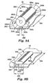
- Figure 7 illustrates an alternate stretch releasing adhesive tape 150 with a generally rectangular cross section 152 that has been twisted to form a series of helical ridges or raised portions 154.
- the helical ridges 154 form discrete raised portions that define a first interface surface area 155 significantly smaller than the potential contact surface area 158 defined by the width 160 and length 162 of the stretch releasing adhesive tape 150 in the un-twisted state.
- Figure 8 illustrates an alternate stretch releasing adhesive tape 170 having a generally rectangular cross section 172.
- Portion 171 of the stretch releasing adhesive tape 170 is compressed against the substrate 22 in its rectangular form.
- Distal end 174 is twisted to define a plurality of helical ridges or raised portions 176.
- the distal end 174 is retained in its uncompressed state so that the helical ridges 176 define a first interface surface area 175 significantly smaller than the potential contact surface area 178 for the distal portion 174 (as defined by the width 180 and length 182).
- the ridges 176 permit that the distal end 174 to be removed from the substrate 22 to serve as pull tab for detaching the compressed portion 171 from the substrate 22.
- Figure 9A illustrates a hollow stretch releasing adhesive tape 280 having a center aperture 282 and a series of adhesive regions 283a, 283b, 283c, 283d (referred to collectively as 283) each having a plurality of discrete raised portions or bumps 284a, 284b, 284c, 284d (referred to collectively as 284).
- the adhesive regions 283 can be continuous or discontinuous, regularly shaped or irregularly shaped, longitudinally oriented or spiral strips, or a variety of other configurations.
- the raised portions or bumps 284 can be a variety of shapes, such as cones, pyramids, hemispherical projections, or irregular shape protrusions.
- a series of non-adhesive regions 285a, 285b, 285c, 285d are positioned between the adhesive regions 283.
- the uncompressed state 286 only the tips of the raised adhesive portions 284c are in contact with the substrate 22, defining a relatively small first interface surface area 288.
- the first interface surface area 288 permits the stretch releasing adhesive tape 280 to be repositioned or removed from the substrate 22 to serve as a pull tab.
- Potential contact surface area 290 is defined by the arc length 292 times the length 294. As is clear from Figure 9A , the potential contact surface area 290 includes adhesive region 283c, portions of adhesive regions 283b, 283d and non-adhesive regions 285b, 285c.
- Figure 9B illustrates the stretch releasing adhesive tape 280 of Figure 9A in the compressed state 296.
- Aperture 282 facilitates compression.
- second interface surface area 298 is greater than the first interface surface area 288.
- the second interface surface area 298 is defined by the width 300 times the length 294.
- the second interface surface area 298 includes the adhesive region 283c, portions of the adhesive regions 283b, 283d and the non-adhesive regions 285b, 285c.
- the second interface surface area 298 is less than the potential contact surface area 290, although in some embodiments, they can be substantially the same.
- Figure 10 is a front view of an article 20 attached to a substrate 22 using a stretch releasing adhesive tape 190 in accordance with the present invention.
- Portion 192 of the stretch releasing adhesive tape 190 is compressed between the substrate 22 and the article 20.
- Compressed portion 192 defines a second interface surface area 196 having a length 198 and a width 200.
- Exposed portion 202 of the stretch releasing adhesive tape 190 is retained in an uncompressed state 204.
- the geometry of the exposed portion 202 defines a first interface surface area 206 with the substrate 22 that is less then the potential contact surface area available for engagement with the substrate 22. Consequently, the level of adhesion of the exposed portion 202 is low enough to permit it to serve as a pull tab for removing the compressed portion 192 from the substrate 22.
- Figure 11 is a front view of an alternate stretch releasing adhesive tape 210 in accordance with the present invention.
- Compressed portion 212 is located between the article 20 and substrate 22. Due to the geometry of the stretch releasing adhesive tape 210, the compressed portion 212 can follow a serpentine or other nonlinear path, thereby increasing the size of the interface surface area 214, and hence the adhesive bond between the substrate 22 and article 20.
- the exposed portion 216 is retained in an uncompressed state 218. Due to the geometry of the stretch releasing adhesive tape 210, the first interface surface area 220 of the exposed portion 216 is formed by raised portions, non-planar surfaces, discontinuous surfaces and other structures that define a surface area significantly less than the potential contact surface area. Therefore, the exposed portion 216 can be easily removed from the substrate 22 to form a pull tab for removing the stretch releasing adhesive tape 210.
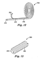
- Figure 12 illustrates a roll 250 of a stretch releasing adhesive tape 252 in accordance with the present invention.
- release liner 254 is located on the stretch releasing adhesive tape 252 to facilitate unrolling
- Frangible connections 256 may optionally be formed in the stretch releasing adhesive tape 252 to facilitate removal of sections without the use of a outting instrument.
- Frangible connections 256 may be a perforation, slit, out or other locations of weakness along the length of the stretch releasing adhesive tape 252.
- Figure 13 is an alternate roll 260 of a stretch releasing adhesive tape 262 in accordance with the present invention.
- the stretch releasing adhesive tape is spiral wound on a core 264.
- the core preferably includes a low adhesion surface or release liner to facilitate removal of the stretch releasing adhesive tape 262.
- Examples of materials suitable for use as liners include kraft papers, polyethylene, polypropylene, polyester or composites of any of these materials which can be coated with release agents such as fluorochemicals or silicone.
- U.S. -A-4,472,480 describes low surface energy perfluorochemical liners.
- the preferred liners are papers, polyolefin films, or polyester films coated with silicone release materials.
- Bxumples of the silicone coated release papers are Polyslik trade silicone release papers supplied by James River Co., H.P. Smith Division (Bedford Park, IL), and silicone coated papers supplied by DCP-Lohja Inc. (Willowbrook, Illinois).
Abstract
Description
- The present invention relates generally to an elongated stretch releasing adhesive tape article with a geometry that provides differential adhesive properties, and in particular, to a geometry that provides regions of reduced adhesion to form pull-tabs.
- Stretch releasing adhesive tapes represent an emerging class of high performance pressure-sensitive adhesives combining strong holding power with clean removal and no surface damage, Such stretch releasing adhesive tapes are useful in a wide variety of assembling, joining, attaching, and mounting applications.
- Adhesive tape strips that can be cleanly removed from a surface by stretching the tape strip are known in the prior art.
U.S. -A-4,024,312 , for example, discloses a highly conformable adhesive tape including a highly extensible and elastic backing film laminated with an adhesive layer. The backing film possesses a lengthwise elongation at break of at least about 200%. The tape is easily stretchable and may be removed from a surface by stretching the tape lengthwise in a direction substantially parallel to the surface.DE-A- 33 31 016 discloses a high elasticity, low plasticity adhesive film based on a thermoplastic rubber and tackifying resins, wherein the adhesive bond can be broken by stretching the adhesive film in the direction of the plane of the adhesive bond. -
U.S. -A- 5,516,581 , assigned to the same assignee as the present invention, discloses a removable adhesive tape having a highly extensible and substantially inelastic backing coated with a layer of pressure sensitive adhesive. The adhesive tape can be removed from a substrate without damaging the substrate by stretching the tape in a direction substantially parallel to the surface of the substrate. The tape backing has a lengthwise elongation at break of from about 150% to about 1200%, a Young's modulus of at least about 17.2MPa to about 500M Pa (about 2.500 psi to about 72.500 psi) and an elastic recovery of less than about 50% after being stretched and removed. -
WO-A-95/06691 -
US-A-5,650,215 discloses a pressure-sensitive adhesive coated article including a tape or a transfer coating, having a microstructured surface, wherein the performance properties of the pressure-sensitive adhesive article can be tailored by independently varying the microstructure and the rheological properties of the pressure-sensitive adhesive. - Commercial stretch releasing adhesive tapes include the product sold under the trade designation COMMAND by 3M Company, St. Paul, Minnesota, and the product sold under the trade designation POWER-STRIPS by Beiersdorf AG, Hamburg Germany. These products are currently manufactured as discrete strips with one end of the strip including a non-adhesive pull tab to facilitate stretching of the strip during removal. The adhesive surfaces of the strip are additionally protected with a release liner.
- Desirable for certain applications is an elongated stretch releasing adhesive tape strip of indefinite length which can be formed into a roll or stack from which segments of selected length can be cut depending on the end use application. The difficulty with providing a long length of stretch releasing tape which can be cut to a selected length is the ability to provide a pull tab at a specific location on the cut strip to serve as a grasping area for stretching the strip from a surface at the time of removal.
-
WO-A-98/06652 -
EP-A-0279579 refers to an adhesive sheet with an irregular section adhesion face which leads to easy peelability and re-use. - It is therefore desirable to provide a stretch releasing adhesive tape article in a long length or a roll that can be cut into discrete strips having any selected length, wherein each strip can be provided with a pull tab or stretch removal tab that can be grasped and pulled by a user to removed the adhesive tape from a substrate.
- The present invention provides a stretch releasing adhesive tape article and methods as defined in the independent claims. Individual embodiments are the subject matter of the dependent claims.
- adhesive tape of the article according to the invention is referred to as stretch releasing adhesive tape although the element need not to be formed as a tape in the sense of e.g. a flak ribbon-like object.
- The present invention relates to various embodiments of a stretch releasing adhesive tape with a geometry that provides differential adhesive properties in a compressed state and an uncompressed state. Adhesion and tack can thus be controlled by varying the amount of compression. Additionally, the present stretch releasing adhesive tape can be easily repositioned prior to compression. A portion of the present stretch releasing adhesive tape can be left in the uncompressed state, thereby providing one or more pull tabs. The stretch releasing adhesive tape of the present invention can be provided in strips of varying lengths, in roll form, or in a stack.
- In one embodiment, the stretch releasing adhesive tape article includes an elongated length of stretch releasing adhesive tape with side surfaces comprising at least one potential contact surface area. At least a portion of the potential contact surface area comprises an adhesive surface having raised portions. The potential contact surface area comprises a first interface surface area in the uncompressed state and a second interface surface area greater than the first interface surface area in the compressed state. The stretch releasing adhesive tape in the uncompressed state can operate as a pull tab.
- In another embodiment, the stretch releasing adhesive tape article comprises an elongated length of stretch releasing adhesive tape with adhesive on all side surfaces. The side surfaces have at least one potential contact surface area. The potential contact surface area has a first interface surface area in an uncompressed state and a second interface surface area greater than the first interface surface area in a compressed state.
- In one embodiment, the stretch releasing adhesive tape comprises a multi-layered structure. The stretch releasing adhesive tape can have one or more elastic or inelastic structural members. The structural member can be foam, film, a monofilament or a variety of other materials. A film can optionally be interposed between the adhesive and the structural member or located at the interior of the structural member. The stretch releasing adhesive tape can be one of a pressure sensitive adhesive tape with an elastic structural member, a pressure sensitive adhesive tape with a highly extensible and substantially inelastic structural member, or a solid pressure sensitive adhesive tape.
- In the various embodiments, the potential contact surface area in the uncompressed state can be a plurality of raised portions, a non-planar structure, a discontinuous surface, or combinations thereof. The stretch releasing adhesive tape in the uncompressed state comprises a cross-section selected from circular, star-shaped, oval, multifaceted or any other geometric shape that provides less surface area in the uncompressed state than in the compressed state. In another embodiment, the potential contact surface area comprises a rectangular cross-section of stretch releasing adhesive tape twisted to form helical ridges. The potential contact surface area can have adhesive regions and non-adhesive regions.
- The elongated length of stretch releasing adhesive tape can be segments or a roll. A release liner may optionally be used. Frangible connections can be formed intermittently along the stretch releasing adhesive tape.
- The present invention is also direct to a method of using a stretch releasing adhesive tape article with differential adhesive properties, including the steps of positioning a potential contact surface area of an elongated length of stretch releasing adhesive tape on a substrate to form a first interface surface area; compressing a portion of the stretch releasing adhesive tape to form a second interface surface area, the second interface surface area being greater than the first interface surface area; and retaining an uncompressed portion of the stretch releasing adhesive tape as a pull tab.
- In another method the steps include providing an elongated length of stretch releasing adhesive tape with a generally rectangular cross section; twisting at least a portion of the stretch releasing adhesive tape to form a twisted portion with a plurality of helical ridges; positioning the stretch releasing adhesive tape on a substrate, the twisted portion defining a first interface surface area; compressing an untwisted portion of the stretch releasing adhesive tape against the substrate to form a second interface surface area greater than the first interface surface area; and retaining the twisted portion in an uncompressed state to form a pull tab.
- The present invention will be further described with reference to the accompanying drawings, in which:
-
Figure 1 is a front view of an article attached to a substrate using a stretch releasing adhesive tape. -
Figure 2 is perspective view of a stretch releasing adhesive tape with a rectangular shape. -
Figure 3A is a perspective view of a stretch releasing adhesive tape in an uncompressed state in accordance with the present invention. -
Figure 3B is a perspective view of the stretch releasing adhesive tape ofFigure 3A in a compressed state. -
Figure 4A is a perspective view of an alternate stretch releasing adhesive tape in an uncompressed state in accordance with the present invention. -
Figure 4B is a perspective view of the stretch releasing adhesive tape ofFigure 4A in the compressed state. -
Figure 5A is perspective view of a stretch releasing adhesive tape in an uncompressed state in accordance with the present invention -
Figure 5B is perspective view of the stretch releasing adhesive tape ofFigure 5A in the compressed state. -
Figure 6A is perspective view of a stretch releasing adhesive tape in an uncompressed state in accordance with the present invention. -
Figure 6B is a perspective view of the stretch releasing adhesive tape ofFigure 6A in the compressed state. -
Figure 7 is a perspective view of a stretch releasing adhesive tape article with helical ridges in accordance with the present invention. -
Figure 8 is a perspective view of a stretch releasing adhesive tape article with a rectangular portion and a portion with helical ridges in accordance with the present invention - invention.
Figures 9A is perspective view of a stretch releasing adhesive tape article with discontinuous adhesive regions in an uncompressed state in accordance with the present invention. -
Figure 9B is a perspective view of the stretch raleasing adhesive tape article ofFigure 9A in the compressed state. -
Figure 10 is a front view of an article attached to a substrate using a stretch releasing adhesive tape in accordance with the present invention. -
Figure 11 is a front view of an article attached to a substrate using an alternate stretch releasing adhesive tape in accordance with the present invention. -
Figure 12 is a perspective view of a stretch releasing adhesive tape article in roll form in accordance with the present invention. -
Figure 13 is a perspective view of an alternate roll of sketch releasing adhesive tape article in accordance with present invention. -
Figure 1 is a front view of anarticle 20 attached to asubstrate 22 using a stretch releasingadhesive tape 24. Aportion 21 of the stretch releasingadhesive tape 24 is compressed between thearticle 20 and thesubstrate 22 to form an adhesive bond. Thestretch releasing adhesive 24 includes apull tab 26 that extends beyond the perimeter of thearticle 20. Thepull tab 26 typically includes non-adhesive surfaces that prevent bonding with thesubstrate 22 or thearticle 20. - Removing the stretch releasing
adhesive tape 24 from thearticle 20 andsubstrate 22 can be carried out by simply stretching the stretch releasingadhesive tape 24 in thedirection 28 and at an angle of less than about 35 degrees with respect to thesubstrate 22. Removal at the appropriate angle will result in no appreciable adhesive residue on thesubstrate 22 and in preventing damage to thesubstrate 22. -
Figure 2 is a perspective view of a segment of a stretch releasingadhesive tape 30 having a generally rectangular cross section. The stretch releasingadhesive tape 30 has alength 32, awidth 34, and athickness 36. The stretch releasingadhesive tape 30 has a potentialcontact surface area 38 and a firstinterface surface area 40 defined by thelength 32 times thewidth 34. As used herein, "potential contact surface area" refers to the surface area on a stretch releasing adhesive tape that can potentially contact a planar substrate, whether or not there is adhesive at the interface with the substrate. For stretch releasing adhesive tapes with a more complex geometry, the potential contact surface area can also be understood as the portion of the side surfaces that are illuminate by a light shined perpendicular throughtransparent substrate 22 onto the stretch releasing adhesive tape. The "first interface surface area" refers to the surface area formed at the actual physical interface between the stretch releasing adhesive tape and thesubstrate 22 in the uncompressed state. Due to the geometry of the stretch releasingadhesive tape 30, the potentialcontact surface area 38 on the stretch releasingadhesive tape 30 and the firstinterface surface area 40 with thesubstrate 22 are substantially the same. - In the embodiment illustrated in
Figure 2 ,portion 42 of the stretch releasingadhesive tape 30 is compressed against thesubstrate 22, whileportion 44 remains uncompressed. No pull tab is provided. The compressedportion 42 forms a strong adhesive bond with thesubstrate 22, while theuncompressed portion 44 initially forms less of an adhesive bond. Over time, however, theuncompressed portion 44 will wet-out against thesubstrate 22 and build adhesion. Consequently, theinterface surface area 40 is effectively the same whether all or a portion of the stretch releasingadhesive tape 30 is compressed against thesubstrate 22. -
Figures 3A and 3B illustrate a stretch releasingadhesive tape 50 with differential adhesive properties in accordance with the present invention. Side surfaces 54 of the stretch releasingadhesive tape 50 include a pressure sensitive adhesive. The pressure sensitive adhesive can cover some or all of the side surfaces 54. For example, the pressure sensitive adhesive can be a continuous or discontinuous region on the side surfaces 54. In the illustrated embodiment, the stretch releasingadhesive tape 50 is a multi-layered structure, including astructural member 51, such as an elastic or inelastic foam, and afilm 53 interposed between thestructural member 51 and theadhesive layer 55 that defines the side surfaces 54. Thestructural member 51 can be concentric or non-concentric with theadhesive layer 55, hollow or solid, or symmetrical or asymmetrical with theadhesive layer 55. Any conventionally known stretch releasing tape, however, can be used in the various embodiments of the present invention, including a pressure sensitive adhesive tape with an elastic core, a pressure sensitive adhesive tape with a highly extensible and substantially inelastic core, or a solid pressure sensitive adhesive. These various structures can be used with any embodiment of the present invention. - Specific tapes suitable for use in the various embodiments of the present invention include the pressure sensitive adhesive tapes with elastic backings described in
U.S. -A- 4,024,312 , the pressure sensitive adhesive tapes with highly extensible and substantially inelastic backings described inU.S. -A-5,516,581 andWO-A-95/0669 DE- C- 33 31 016 . In addition, the stretch releasing adhesive tape of the present invention can include a splittable layer such as the layers described inWO-A-98/21285 WO-A-99/31193 -
Figure 3A illustrates the stretch releasingadhesive tape 50 adhered to asubstrate 22 in anuncompressed state 52. The adhesive side surfaces 54 have a potentialcontact surface area 56 defined byarc length 60times length 62. The firstinterface surface area 58, however, is defined by arelength 64 times thelength 62. The circular cross section of the stretch releasing adhesive 50 causes the firstinterface surface area 58 with thesubstrate 22 to be significantly smaller than the potentialcontact surface area 56. -
Figure 3B illustrates the stretch releasingadhesive tape 50 ofFigure 3A in the compressedstate 70. In thecompressed state 70, the potentialcontact surface area 56 defines a secondinterface surface area 72 greater than the firstinterface surface area 58. The "second interface surface area" refers to the surface area formed at the actual physical interface between the stretch releasing adhesive tape and thesubstrate 22 in the compressed state. In the embodiment ofFigure 3B , the secondinterface surface area 72 is defined by the width 71 times thelength 62. As illustrated inFigure 3B , the secondinterface surface area 72 is less than the potentialcontact surface area 56, although in some embodiments, they can be substantially the same. - Due to the increase in surface area, the stretch releasing
adhesive tape 50 has greater adhesion with thesubstrate 22 in the compressedstate 70 than in theuncompressed state 52. By selectively leaving portions of the stretch releasingadhesive tape 50 in the uncompressed state, those portions can be later removed from thesubstrate 22 and used as pull tabs (seeFigures 10 and 11 ). Additionally, the firstinterface surface area 58 can be made sufficiently small that the pressure sensitiveadhesive tape 50 can be easily repositioned prior to compression into thecompressed state 70. -
Figure 4A illustrates an alternate stretch releasingadhesive tape 80 in anuncompressed state 82 in accordance with the present invention. The stretch releasingadhesive tape 80 includes a series of raisedportions potential contact surface 86 includes raisedportions portions interface surface areas substrate 22 in theuncompressed state 82. Rather than the single continuousinterface surface area 58 ofFigure 3A , theinterface surface areas uncompressed state 82, the level of adhesion generated by the firstinterface surface areas adhesive tape 80 or detach a portion of the stretch releasingadhesive tape 80 from thesubstrate 22 and use the detached portion as a pul1 tab. -
Figure 4B illustrates the stretch releasingadhesive tape 80 ofFigure 4A in acompressed state 84. In thecompressed state 84, the firstinterface surface areas interface surface area 95 that is defined by thewidth 97 times thelength 99. In the embodiment ofFigure 4B , the secondinterface surface area 95 is substantially the same as the potentialcontact surface area 86. Once the stretch releasingadhesive tape 80 is compressed against thesubstrate 22, as illustrated inFigure 4B , it cannot be easily removed without a pull tab. By selectively leaving portions of the stretch releasingadhesive tape 80 in the uncompressed state, the uncompressed portions can be used as pull tabs. -
Figures 5A and 5B illustrate a cross sectional view of an alternate stretch releasingadhesive tape 100 in accordance with the present invention.Figure 5A illustrates the stretch releasing adhesive tape in theuncompressed state 102. In theuncompressed state 102, the stretch releasingadhesive tape 100 includes a series of raisedportions contact surface area 110 is defined by thesegments length 109. In theuncompressed state 102, however, tips of the raisedportions length 109 define a pair of discontinuous, non-planar firstinterface surface areas substrate 22. The sum of the firstinterface surface areas contact surface area 110. If a portion of the stretch releasingadhesive tape 100 is retained in theuncompressed state 102, that portion can be removed from thesubstrate 22 and used as a pull tab or repositioned. -
Figure 5B illustrates the stretch releasingadhesive tape 100 ofFigure 5A in acompressed state 116. Raisedportions substrate 22 so that the secondinterface surface area 118 is the sum of thesegments length 109, substantially the same as the potentialcontact surface area 110. -
Figure 6A and 6B illustrate an alternate stretch releasingadhesive tape 130 in accordance with the present invention.Figure 6A illustrates the stretch releasingadhesive tape 130 in theuncompressed state 132. The stretch releasingadhesive tape 130 includes a series of longitudinal ridges or raisedportions 134 that define the firstinterface surface area 136. The raisedportions 134 can be formed on one or more surfaces of the stretch releasingadhesive tape 130. In the embodiment illustrated inFigure 6A , the firstinterface surface area 136 is a series of elongated strips that correspond to the tips of the raisedportions 134. The potentialcontact surface area 138 is defined by the contour of the raisedportions 134 times thelength 142 of the stretch releasingadhesive tape 130. The firstinterface surface area 136, however, is significantly smaller than the potentialcontact surface area 138 due to the non-planar structure defined by theridges 134. -
Figure 6B illustrates the stretch releasingadhesive tape 130 ofFigure 6A in thecompressed state 146. In the embodiment illustrated inFigure 6B , the secondinterface surface area 144 is greater than the firstinterface surface area 136, but less than the potentialcontact surface area 138. This result is due to incomplete compression of the stretch releasingadhesive tape 130 at thelocations 148 against thesubstrate 22. In an alternate embodiment, the stretch releasingadhesive tape 130 is fully compressed so that the secondinterface surface area 144 is substantially the same as the potentialcontact surface area 138. -
Figure 7 illustrates an alternate stretch releasingadhesive tape 150 with a generallyrectangular cross section 152 that has been twisted to form a series of helical ridges or raisedportions 154. Thehelical ridges 154 form discrete raised portions that define a firstinterface surface area 155 significantly smaller than the potentialcontact surface area 158 defined by thewidth 160 andlength 162 of the stretch releasingadhesive tape 150 in the un-twisted state. -
Figure 8 illustrates an alternate stretch releasingadhesive tape 170 having a generallyrectangular cross section 172.Portion 171 of the stretch releasingadhesive tape 170 is compressed against thesubstrate 22 in its rectangular form.Distal end 174 is twisted to define a plurality of helical ridges or raisedportions 176. Thedistal end 174 is retained in its uncompressed state so that thehelical ridges 176 define a firstinterface surface area 175 significantly smaller than the potentialcontact surface area 178 for the distal portion 174 (as defined by thewidth 180 and length 182). Theridges 176 permit that thedistal end 174 to be removed from thesubstrate 22 to serve as pull tab for detaching thecompressed portion 171 from thesubstrate 22. -
Figure 9A illustrates a hollow stretch releasingadhesive tape 280 having acenter aperture 282 and a series ofadhesive regions bumps non-adhesive regions uncompressed state 286, only the tips of the raisedadhesive portions 284c are in contact with thesubstrate 22, defining a relatively small firstinterface surface area 288. In theuncompressed state 286, the firstinterface surface area 288 permits the stretch releasingadhesive tape 280 to be repositioned or removed from thesubstrate 22 to serve as a pull tab. - Potential
contact surface area 290 is defined by thearc length 292 times thelength 294. As is clear fromFigure 9A , the potentialcontact surface area 290 includesadhesive region 283c, portions ofadhesive regions non-adhesive regions -
Figure 9B illustrates the stretch releasingadhesive tape 280 ofFigure 9A in thecompressed state 296.Aperture 282 facilitates compression. In thecompressed state 296, second interface surface area 298 is greater than the firstinterface surface area 288. The second interface surface area 298 is defined by thewidth 300 times thelength 294. The second interface surface area 298 includes theadhesive region 283c, portions of theadhesive regions non-adhesive regions Figure 9B , the second interface surface area 298 is less than the potentialcontact surface area 290, although in some embodiments, they can be substantially the same. -
Figure 10 is a front view of anarticle 20 attached to asubstrate 22 using a stretch releasingadhesive tape 190 in accordance with the present invention.Portion 192 of the stretch releasingadhesive tape 190 is compressed between thesubstrate 22 and thearticle 20.Compressed portion 192 defines a secondinterface surface area 196 having alength 198 and awidth 200. -
Exposed portion 202 of the stretch releasingadhesive tape 190 is retained in anuncompressed state 204. The geometry of the exposedportion 202 defines a firstinterface surface area 206 with thesubstrate 22 that is less then the potential contact surface area available for engagement with thesubstrate 22. Consequently, the level of adhesion of the exposedportion 202 is low enough to permit it to serve as a pull tab for removing thecompressed portion 192 from thesubstrate 22. -
Figure 11 is a front view of an alternate stretch releasingadhesive tape 210 in accordance with the present invention.Compressed portion 212 is located between thearticle 20 andsubstrate 22. Due to the geometry of the stretch releasingadhesive tape 210, thecompressed portion 212 can follow a serpentine or other nonlinear path, thereby increasing the size of theinterface surface area 214, and hence the adhesive bond between thesubstrate 22 andarticle 20. - The exposed
portion 216 is retained in anuncompressed state 218. Due to the geometry of the stretch releasingadhesive tape 210, the firstinterface surface area 220 of the exposedportion 216 is formed by raised portions, non-planar surfaces, discontinuous surfaces and other structures that define a surface area significantly less than the potential contact surface area. Therefore, the exposedportion 216 can be easily removed from thesubstrate 22 to form a pull tab for removing the stretch releasingadhesive tape 210. -
Figure 12 illustrates aroll 250 of a stretch releasingadhesive tape 252 in accordance with the present invention. In the illustrated embodiment,release liner 254 is located on the stretch releasingadhesive tape 252 to facilitate unrolling,Frangible connections 256 may optionally be formed in the stretch releasingadhesive tape 252 to facilitate removal of sections without the use of a outting instrument.Frangible connections 256 may be a perforation, slit, out or other locations of weakness along the length of the stretch releasingadhesive tape 252. -
Figure 13 is analternate roll 260 of a stretch releasingadhesive tape 262 in accordance with the present invention. The stretch releasing adhesive tape is spiral wound on acore 264. The core preferably includes a low adhesion surface or release liner to facilitate removal of the stretch releasingadhesive tape 262. - Examples of materials suitable for use as liners include kraft papers, polyethylene, polypropylene, polyester or composites of any of these materials which can be coated with release agents such as fluorochemicals or silicone.
U.S. -A-4,472,480 describes low surface energy perfluorochemical liners. The preferred liners are papers, polyolefin films, or polyester films coated with silicone release materials. Bxumples of the silicone coated release papers are Polyslik trade silicone release papers supplied by James River Co., H.P. Smith Division (Bedford Park, IL), and silicone coated papers supplied by DCP-Lohja Inc. (Willowbrook, Illinois). - While several embodiments of the invention have been illustrated and described, it will be recognized that various changes and modifications may be made without deviating from the inventive concept set for the above. Any of the features of the various embodiments disclosed herein can be combined. changes and from the inventive concept Thus, the scope of the present invention should not be limited to the structures described in this application, but only by the structures described by the language of the claims and the equivalents of those structures.
Claims (20)
- A stretch releasing adhesive tape article with differential adhesive properties in an uncompressed state and a compressed state, comprising:an elongated length of stretch releasing adhesive tape (80,100,130,150,170,280) with side surfaces comprising at least one potential contact surface area (86,110,138,158,178,290) that can potentially contact a planar substrate, at least a portion of the potential contact surface area (86,110,138,158,178,290) comprising an adhesive surface having at least one raised portion (96C,96D,104B,104C, 134,154,176,284b,284c,284d), the potential contact surface area (86,110,138,158,178,290), in the uncompressed state, comprising a first interface surface area (92,94,106,107,136,155,175,288) formed at the actual physical interface between the stretch releasing adhesive tape (80,100,130,150,170,280) and the substrate in the uncompressed state of the stretch releasing adhesive tape (80,100,130,150,170,280) and, in the compressed state, a second interface surface area (95,118,144,298) formed at the actual physical interface between the stretch releasing adhesive tape (80,100,130,150,170,280) and the substrate in the compressed state of the stretch releasing adhesive tape (80,100,130,150,170,280), the second interface surface area (95,118,144,298) being greater than the first interface surface area (92,94,106,107,136,155,175,288).
- The article of claim 1 wherein a portion of the stretch releasing adhesive tape (80,100,130,150,170,280) in the uncompressed state comprises a pull tab.
- The article of claim 1 or 2 wherein the stretch releasing adhesive tape comprises a multi-layer structure.
- The article of any one of claims 1 to 3 wherein the stretch releasing adhesive tape comprises a structural member.
- The article of claim 4 wherein the structural member is selected from one of a film, an elastic foam, an inelastic foam, a monofilament.
- The article of any one of claims 1 to 5 wherein the stretch releasing adhesive tape (280) comprises a hollow portion.
- The article of any one of claims 1 to 6 wherein the stretch releasing adhesive tape (80,100,130,150,170,280) comprises one of a pressure sensitive adhesive tape with an elastic structural member, a pressure sensitive adhesive tape with a highly extensible and substantially inelastic structural member, or a solid pressure sensitive adhesive.
- The article of any one of claims 1 to 7 wherein the potential contact surface area (86,110,138,158,178,290) in the uncompressed state comprises a non-planar structure.
- The article of any one of claims 1 to 8 wherein the potential contact surface area (86,110,138,158,178,290) in the uncompressed state comprises a discontinuous surface.
- The article of any one of claims 1 to 9 wherein the potential contact surface area in the compressed state comprises a substantially continuous surface.
- The article of any one of claims 1 to 10 wherein the stretch releasing adhesive tape (80,100,130,150,170,280) In the uncompressed state comprises a cross-section selected from circular, star-shaped, oval, or multi-faceted.
- The article of any one of claims 1 to 11 wherein the stretch releasing adhesive tape (80,100,130,150,170,280) in the uncompressed state comprises a geometric shape that provides less surface area in the uncompressed state than in the compressed state.
- The article of any one of claims 1 to 12 wherein the potential contact surface area (158,178) comprises a rectangular cross-section of stretch releasing adhesive tape (150,170) twisted to form helical ridges (154,176).
- The article of any one of claims 1 to 13 wherein the elongated length of stretch releasing adhesive tape comprises a roll of stretch releasing adhesive tape.
- The article of any one of claims 1 to 14 comprising a release liner adhered to the potential contact surface area.
- The article of any one of claims 1 to 15 comprising frangible connections formed intermittently along the stretch releasing adhesive tape.
- The article of any one of claims 1 to 11 wherein the stretch releasing adhesive tape (80,100,130,150,170) comprises adhesive on the entire potential contact surface area (86,110,138,158,178).
- The article of any one of claims 1 to 11 wherein the potential contact surface area (290) comprises adhesive regions (283b,283c,283d) and non-adhesive regions (285b,285c).
- A method of using a stretch releasing adhesive tape article with differential adhesive properties, comprising the steps of:- providing an elongated length of stretch releasing adhesive tape (50,80,100,130,150,170,190,212,252,262,280) with side surfaces comprising at least one potential contact surface area (56,86,110,138,158,178,290) that can potentially contact a planar substrate (22),- positioning the potential contact surface area (56,86,110,138, 158,178,290) of the stretch releasing adhesive tape (50,80,100,130,150,170,190,212,252,262,280) on the substrate (22) to form a first interface surface area
(40,92,94,106,107,136,155,175,288) formed at the actual physical interface between the stretch releasing adhesive tape (80,100,130,150,170,280) and the substrate (22) in the uncompressed state of the stretch releasing adhesive tape (50,80,100,130,150,170,190,212,252,262,280);- compressing a portion of the stretch releasing adhesive tape (50,80,100,130,150,170,190,212,252,262,280) to form a second interface surface area (72,95,118,144,298) formed at the actual physical interface between the stretch releasing adhesive tape (80,100,130,150,170,280) and the substrate (22) in the compressed state of the stretch releasing adhesive tape (50,80,100,130,150,170,190,212,252,262,280), the second interface surface area (72,95,118,144,298) being greater than the first interface surface area (40,92,94,106,107,136,155,175,288); and- retaining an uncompressed portion of the stretch releasing adhesive tape (50,80,100,130,150,170,190,212,252,262,280) as a pull tab. - The method according to claim 19, wherein:- the step of providing the elongated length of stretch releasing adhesive tape comprises providing an elongated length of stretch releasing adhesive tape (150,170) with a generally rectangular cross section (152,172);- twisting at least a portion of the stretch releasing adhesive tape (150,170) to form a twisted portion with a plurality of helical ridges (154,176) and an untwisted portion (171) wherein the twisted portion forms the first interface surface area (155,175;- positioning the stretch releasing adhesive tape (150,170) on a substrate (22);- compressing the untwisted portion (171) of the stretch releasing adhesive tape (150,170) against the substrate (22) to form a second interface surface area adhered to the substrate (22) and greater than the first interface surface area (155,175); and- retaining the twisted portion in an uncompressed state to form a pull tab.
Applications Claiming Priority (3)
| Application Number | Priority Date | Filing Date | Title |
|---|---|---|---|
| US489361 | 2000-01-21 | ||
| US09/489,361 US6410135B1 (en) | 2000-01-21 | 2000-01-21 | Stretch releasing adhesive tape with differential adhesive properties |
| PCT/US2000/034929 WO2001053422A1 (en) | 2000-01-21 | 2000-12-21 | Stretch releasing adhesive tape with differential adhesive properties |
Publications (2)
| Publication Number | Publication Date |
|---|---|
| EP1261674A1 EP1261674A1 (en) | 2002-12-04 |
| EP1261674B1 true EP1261674B1 (en) | 2011-11-23 |
Family
ID=23943537
Family Applications (1)
| Application Number | Title | Priority Date | Filing Date |
|---|---|---|---|
| EP00989395A Expired - Lifetime EP1261674B1 (en) | 2000-01-21 | 2000-12-21 | Stretch releasing adhesive tape with differential adhesive properties |
Country Status (7)
| Country | Link |
|---|---|
| US (2) | US6410135B1 (en) |
| EP (1) | EP1261674B1 (en) |
| JP (1) | JP5386054B2 (en) |
| AT (1) | ATE534713T1 (en) |
| AU (1) | AU2001225904A1 (en) |
| CA (1) | CA2396758A1 (en) |
| WO (1) | WO2001053422A1 (en) |
Families Citing this family (22)
| Publication number | Priority date | Publication date | Assignee | Title |
|---|---|---|---|---|
| DE19649728A1 (en) * | 1996-11-30 | 1998-06-18 | Beiersdorf Ag | duct tape |
| US6303423B1 (en) * | 1998-12-21 | 2001-10-16 | Megic Corporation | Method for forming high performance system-on-chip using post passivation process |
| US6410135B1 (en) * | 2000-01-21 | 2002-06-25 | 3M Innovative Properties Company | Stretch releasing adhesive tape with differential adhesive properties |
| US7063887B2 (en) * | 2002-02-04 | 2006-06-20 | 3M Innovative Properties Company | Stretch releasable foams, articles including same and methods for the manufacture thereof |
| DE10314764A1 (en) * | 2003-03-31 | 2004-10-14 | Tesa Ag | Process for the production of structured PSAs and their use |
| EP1548691A4 (en) * | 2003-04-02 | 2009-04-22 | Panasonic Corp | Method of manufacturing plasma display device |
| US8384189B2 (en) * | 2005-03-29 | 2013-02-26 | Megica Corporation | High performance system-on-chip using post passivation process |
| US7506450B2 (en) * | 2006-06-30 | 2009-03-24 | The Stanley Works | Adhesive mount for a leveling device and a leveling device |
| US20080135159A1 (en) * | 2006-12-12 | 2008-06-12 | 3M Innovative Properties Company | Stretch releasing pressure-sensitive adhesive articles and methods of using the same |
| US7857130B2 (en) * | 2007-06-28 | 2010-12-28 | 3M Innovative Properties Company | Removable adhesive tape and pull tab film, and kits |
| TWI454384B (en) * | 2011-07-28 | 2014-10-01 | Young Lighting Technology Inc | Adhered structure |
| US8889240B2 (en) | 2012-12-28 | 2014-11-18 | 3M Innovative Properties Company | Stretch release article |
| US9184083B2 (en) | 2013-07-29 | 2015-11-10 | 3M Innovative Properties Company | Apparatus, hybrid laminated body, method and materials for temporary substrate support |
| US9554674B2 (en) | 2013-10-08 | 2017-01-31 | Liberty Hardware Mfg. Corp. | Shower rod mounting assembly |
| US10537817B2 (en) | 2014-02-12 | 2020-01-21 | InRoad Toys, LLC | Construction system for creating autonomous control system stimuli and a complete deterministic operational environment for mobile agents using printed adhesive tape and other accessories |
| US9320978B2 (en) | 2014-02-12 | 2016-04-26 | InRoad Toys, LLC | Construction system for creating a customizable adhesive toy playscape using printed adhesive tape and other accessories |
| US9895622B2 (en) | 2014-02-12 | 2018-02-20 | InRoad Toys, LLC | Construction system for creating a customizable play surface composed of printed adhesive tape and other accessories for autonomously controlled mobile agents |
| US10221883B2 (en) | 2017-04-07 | 2019-03-05 | Artskills, Inc. | Apparatus for supporting articles |
| DE102018214237A1 (en) * | 2018-05-28 | 2019-11-28 | Tesa Se | Removable pressure-sensitive adhesive strip |
| US11197512B2 (en) | 2020-03-27 | 2021-12-14 | Michael Andrew Twombly | Detachable, retro fitting light accessory for high-heeled shoes |
| US20220363951A1 (en) * | 2021-05-12 | 2022-11-17 | The Hillman Group, Inc. | Adhesive wall mount systems configured for sequential release of adhesive |
| EP4347738A1 (en) * | 2021-05-28 | 2024-04-10 | Microsoft Technology Licensing, LLC | Anisotropic stretch release tape |
Family Cites Families (15)
| Publication number | Priority date | Publication date | Assignee | Title |
|---|---|---|---|---|
| JPS4910524Y1 (en) * | 1967-04-14 | 1974-03-13 | ||
| US4024312A (en) | 1976-06-23 | 1977-05-17 | Johnson & Johnson | Pressure-sensitive adhesive tape having extensible and elastic backing composed of a block copolymer |
| US4472480A (en) | 1982-07-02 | 1984-09-18 | Minnesota Mining And Manufacturing Company | Low surface energy liner of perfluoropolyether |
| DE3331016A1 (en) | 1983-04-06 | 1984-10-11 | Beiersdorf Ag, 2000 Hamburg | Adhesive film for releasable adhesive bonds |
| US5516581A (en) | 1990-12-20 | 1996-05-14 | Minnesota Mining And Manufacturing Company | Removable adhesive tape |
| JP3547747B2 (en) | 1993-08-31 | 2004-07-28 | ミネソタ マイニング アンド マニュファクチャリング カンパニー | Removable foam adhesive tape |
| CA2173855C (en) | 1993-10-29 | 2007-06-26 | Mieczyslaw H. Mazurek | Pressure-sensitive adhesives having microstructured surfaces |
| DE4431914C2 (en) * | 1994-09-08 | 1996-10-17 | Beiersdorf Ag | Strip of an adhesive film for a residue-free, removable adhesive and its use |
| JPH08158495A (en) * | 1994-12-12 | 1996-06-18 | Bridgestone Corp | Sealing material |
| US5795636A (en) * | 1995-11-15 | 1998-08-18 | Minnesota Mining And Manufacturing Company | Positionable and repositionable adhesive article |
| JPH1017827A (en) * | 1996-07-04 | 1998-01-20 | Sekisui Chem Co Ltd | Press bonding type, pressure-sensitive adhesive double coated sheet |
| DE19631964A1 (en) | 1996-08-08 | 1998-02-12 | Beiersdorf Ag | Cutting device |
| US6004642A (en) | 1996-11-08 | 1999-12-21 | 3M Innovative Properties Company | Internally separable tape laminate |
| US6972141B1 (en) | 1997-12-12 | 2005-12-06 | 3M Innovative Properties Company | Removable adhesive tape laminate and separable fastener |
| US6410135B1 (en) * | 2000-01-21 | 2002-06-25 | 3M Innovative Properties Company | Stretch releasing adhesive tape with differential adhesive properties |
-
2000
- 2000-01-21 US US09/489,361 patent/US6410135B1/en not_active Expired - Lifetime
- 2000-12-21 AT AT00989395T patent/ATE534713T1/en active
- 2000-12-21 AU AU2001225904A patent/AU2001225904A1/en not_active Abandoned
- 2000-12-21 CA CA002396758A patent/CA2396758A1/en not_active Abandoned
- 2000-12-21 JP JP2001553885A patent/JP5386054B2/en not_active Expired - Fee Related
- 2000-12-21 EP EP00989395A patent/EP1261674B1/en not_active Expired - Lifetime
- 2000-12-21 WO PCT/US2000/034929 patent/WO2001053422A1/en active Application Filing
-
2002
- 2002-05-08 US US10/142,663 patent/US6821619B2/en not_active Expired - Lifetime
Also Published As
| Publication number | Publication date |
|---|---|
| CA2396758A1 (en) | 2001-07-26 |
| JP2003520885A (en) | 2003-07-08 |
| US20020132115A1 (en) | 2002-09-19 |
| ATE534713T1 (en) | 2011-12-15 |
| WO2001053422A1 (en) | 2001-07-26 |
| US6821619B2 (en) | 2004-11-23 |
| AU2001225904A1 (en) | 2001-07-31 |
| US6410135B1 (en) | 2002-06-25 |
| JP5386054B2 (en) | 2014-01-15 |
| EP1261674A1 (en) | 2002-12-04 |
Similar Documents
| Publication | Publication Date | Title |
|---|---|---|
| EP1261674B1 (en) | Stretch releasing adhesive tape with differential adhesive properties | |
| EP1214384B1 (en) | Stretch releasing adhesive tape with integral pull tab | |
| EP1206501B1 (en) | Stretch releasing adhesive tape with segmented release liner | |
| EP0800561B1 (en) | Tape for rough surfaces | |
| JP4874544B2 (en) | Stretchable peelable tape flag | |
| JPH05117607A (en) | Endlessly rolled composite laminated adhesive tape and preparation of the laminated adhesive tape roll | |
| CA2692184C (en) | Removable adhesive tape with foldable pull tab | |
| JP2015520791A (en) | Stretch release article | |
| JP2000096007A (en) | Adhesive tape strip | |
| WO2006039027A1 (en) | Stretch releasing adhesive article for fragile surfaces | |
| KR100826075B1 (en) | Core | |
| JPH0538348A (en) | Adhesive sheet | |
| JPH08109355A (en) | Adhesive tape structure | |
| JPH0673140U (en) | Roll adhesive tape | |
| JPH1035963A (en) | Adhesive tape used for both temporally fixing and connection of terminal part of wound sheet | |
| JPH0762307A (en) | Pressure-sensitive adhesive tape provided with release paper | |
| JP2004250618A (en) | Double-sided adhesive tape made of rubber | |
| JPH08169820A (en) | Strip fixing base sheet |
Legal Events
| Date | Code | Title | Description |
|---|---|---|---|
| PUAI | Public reference made under article 153(3) epc to a published international application that has entered the european phase |
Free format text: ORIGINAL CODE: 0009012 |
|
| 17P | Request for examination filed |
Effective date: 20020718 |
|
| AK | Designated contracting states |
Kind code of ref document: A1 Designated state(s): AT BE CH CY DE DK ES FI FR GB GR IE IT LI LU MC NL PT SE TR |
|
| AX | Request for extension of the european patent |
Free format text: AL;LT;LV;MK;RO;SI |
|
| GRAP | Despatch of communication of intention to grant a patent |
Free format text: ORIGINAL CODE: EPIDOSNIGR1 |
|
| GRAS | Grant fee paid |
Free format text: ORIGINAL CODE: EPIDOSNIGR3 |
|
| GRAA | (expected) grant |
Free format text: ORIGINAL CODE: 0009210 |
|
| AK | Designated contracting states |
Kind code of ref document: B1 Designated state(s): AT BE CH CY DE DK ES FI FR GB GR IE IT LI LU MC NL PT SE TR |
|
| REG | Reference to a national code |
Ref country code: GB Ref legal event code: FG4D |
|
| REG | Reference to a national code |
Ref country code: CH Ref legal event code: EP |
|
| REG | Reference to a national code |
Ref country code: IE Ref legal event code: FG4D |
|
| REG | Reference to a national code |
Ref country code: DE Ref legal event code: R096 Ref document number: 60046691 Country of ref document: DE Effective date: 20120126 |
|
| REG | Reference to a national code |
Ref country code: NL Ref legal event code: VDEP Effective date: 20111123 |
|
| PG25 | Lapsed in a contracting state [announced via postgrant information from national office to epo] |
Ref country code: BE Free format text: LAPSE BECAUSE OF FAILURE TO SUBMIT A TRANSLATION OF THE DESCRIPTION OR TO PAY THE FEE WITHIN THE PRESCRIBED TIME-LIMIT Effective date: 20111123 Ref country code: NL Free format text: LAPSE BECAUSE OF FAILURE TO SUBMIT A TRANSLATION OF THE DESCRIPTION OR TO PAY THE FEE WITHIN THE PRESCRIBED TIME-LIMIT Effective date: 20111123 Ref country code: GR Free format text: LAPSE BECAUSE OF FAILURE TO SUBMIT A TRANSLATION OF THE DESCRIPTION OR TO PAY THE FEE WITHIN THE PRESCRIBED TIME-LIMIT Effective date: 20120224 Ref country code: SE Free format text: LAPSE BECAUSE OF FAILURE TO SUBMIT A TRANSLATION OF THE DESCRIPTION OR TO PAY THE FEE WITHIN THE PRESCRIBED TIME-LIMIT Effective date: 20111123 Ref country code: PT Free format text: LAPSE BECAUSE OF FAILURE TO SUBMIT A TRANSLATION OF THE DESCRIPTION OR TO PAY THE FEE WITHIN THE PRESCRIBED TIME-LIMIT Effective date: 20120323 |
|
| PG25 | Lapsed in a contracting state [announced via postgrant information from national office to epo] |
Ref country code: CY Free format text: LAPSE BECAUSE OF FAILURE TO SUBMIT A TRANSLATION OF THE DESCRIPTION OR TO PAY THE FEE WITHIN THE PRESCRIBED TIME-LIMIT Effective date: 20111123 |
|
| PG25 | Lapsed in a contracting state [announced via postgrant information from national office to epo] |
Ref country code: DK Free format text: LAPSE BECAUSE OF FAILURE TO SUBMIT A TRANSLATION OF THE DESCRIPTION OR TO PAY THE FEE WITHIN THE PRESCRIBED TIME-LIMIT Effective date: 20111123 Ref country code: MC Free format text: LAPSE BECAUSE OF NON-PAYMENT OF DUE FEES Effective date: 20111231 |
|
| REG | Reference to a national code |
Ref country code: CH Ref legal event code: PL |
|
| PG25 | Lapsed in a contracting state [announced via postgrant information from national office to epo] |
Ref country code: IT Free format text: LAPSE BECAUSE OF FAILURE TO SUBMIT A TRANSLATION OF THE DESCRIPTION OR TO PAY THE FEE WITHIN THE PRESCRIBED TIME-LIMIT Effective date: 20111123 |
|
| REG | Reference to a national code |
Ref country code: AT Ref legal event code: MK05 Ref document number: 534713 Country of ref document: AT Kind code of ref document: T Effective date: 20111123 |
|
| REG | Reference to a national code |
Ref country code: IE Ref legal event code: MM4A |
|
| PLBE | No opposition filed within time limit |
Free format text: ORIGINAL CODE: 0009261 |
|
| STAA | Information on the status of an ep patent application or granted ep patent |
Free format text: STATUS: NO OPPOSITION FILED WITHIN TIME LIMIT |
|
| 26N | No opposition filed |
Effective date: 20120824 |
|
| PG25 | Lapsed in a contracting state [announced via postgrant information from national office to epo] |
Ref country code: IE Free format text: LAPSE BECAUSE OF NON-PAYMENT OF DUE FEES Effective date: 20111221 Ref country code: LI Free format text: LAPSE BECAUSE OF NON-PAYMENT OF DUE FEES Effective date: 20111231 Ref country code: CH Free format text: LAPSE BECAUSE OF NON-PAYMENT OF DUE FEES Effective date: 20111231 |
|
| REG | Reference to a national code |
Ref country code: DE Ref legal event code: R097 Ref document number: 60046691 Country of ref document: DE Effective date: 20120824 |
|
| PG25 | Lapsed in a contracting state [announced via postgrant information from national office to epo] |
Ref country code: AT Free format text: LAPSE BECAUSE OF FAILURE TO SUBMIT A TRANSLATION OF THE DESCRIPTION OR TO PAY THE FEE WITHIN THE PRESCRIBED TIME-LIMIT Effective date: 20111123 |
|
| PG25 | Lapsed in a contracting state [announced via postgrant information from national office to epo] |
Ref country code: ES Free format text: LAPSE BECAUSE OF FAILURE TO SUBMIT A TRANSLATION OF THE DESCRIPTION OR TO PAY THE FEE WITHIN THE PRESCRIBED TIME-LIMIT Effective date: 20120305 |
|
| PG25 | Lapsed in a contracting state [announced via postgrant information from national office to epo] |
Ref country code: LU Free format text: LAPSE BECAUSE OF NON-PAYMENT OF DUE FEES Effective date: 20111221 |
|
| PG25 | Lapsed in a contracting state [announced via postgrant information from national office to epo] |
Ref country code: FI Free format text: LAPSE BECAUSE OF FAILURE TO SUBMIT A TRANSLATION OF THE DESCRIPTION OR TO PAY THE FEE WITHIN THE PRESCRIBED TIME-LIMIT Effective date: 20111123 |
|
| PG25 | Lapsed in a contracting state [announced via postgrant information from national office to epo] |
Ref country code: TR Free format text: LAPSE BECAUSE OF FAILURE TO SUBMIT A TRANSLATION OF THE DESCRIPTION OR TO PAY THE FEE WITHIN THE PRESCRIBED TIME-LIMIT Effective date: 20111123 |
|
| REG | Reference to a national code |
Ref country code: FR Ref legal event code: PLFP Year of fee payment: 16 |
|
| PGFP | Annual fee paid to national office [announced via postgrant information from national office to epo] |
Ref country code: GB Payment date: 20151216 Year of fee payment: 16 |
|
| PGFP | Annual fee paid to national office [announced via postgrant information from national office to epo] |
Ref country code: FR Payment date: 20151110 Year of fee payment: 16 |
|
| PGFP | Annual fee paid to national office [announced via postgrant information from national office to epo] |
Ref country code: DE Payment date: 20161213 Year of fee payment: 17 |
|
| GBPC | Gb: european patent ceased through non-payment of renewal fee |
Effective date: 20161221 |
|
| REG | Reference to a national code |
Ref country code: FR Ref legal event code: ST Effective date: 20170831 |
|
| PG25 | Lapsed in a contracting state [announced via postgrant information from national office to epo] |
Ref country code: FR Free format text: LAPSE BECAUSE OF NON-PAYMENT OF DUE FEES Effective date: 20170102 |
|
| PG25 | Lapsed in a contracting state [announced via postgrant information from national office to epo] |
Ref country code: GB Free format text: LAPSE BECAUSE OF NON-PAYMENT OF DUE FEES Effective date: 20161221 |
|
| REG | Reference to a national code |
Ref country code: DE Ref legal event code: R119 Ref document number: 60046691 Country of ref document: DE |
|
| PG25 | Lapsed in a contracting state [announced via postgrant information from national office to epo] |
Ref country code: DE Free format text: LAPSE BECAUSE OF NON-PAYMENT OF DUE FEES Effective date: 20180703 |