EP1261273B1 - Method and system for prescribing and/or dispensing ophthalmic lenses - Google Patents
Method and system for prescribing and/or dispensing ophthalmic lenses Download PDFInfo
- Publication number
- EP1261273B1 EP1261273B1 EP01907258.6A EP01907258A EP1261273B1 EP 1261273 B1 EP1261273 B1 EP 1261273B1 EP 01907258 A EP01907258 A EP 01907258A EP 1261273 B1 EP1261273 B1 EP 1261273B1
- Authority
- EP
- European Patent Office
- Prior art keywords
- wearer
- head
- eye
- task
- progressive ophthalmic
- Prior art date
- Legal status (The legal status is an assumption and is not a legal conclusion. Google has not performed a legal analysis and makes no representation as to the accuracy of the status listed.)
- Expired - Lifetime
Links
Images


Classifications
-
- G—PHYSICS
- G02—OPTICS
- G02C—SPECTACLES; SUNGLASSES OR GOGGLES INSOFAR AS THEY HAVE THE SAME FEATURES AS SPECTACLES; CONTACT LENSES
- G02C7/00—Optical parts
- G02C7/02—Lenses; Lens systems ; Methods of designing lenses
- G02C7/06—Lenses; Lens systems ; Methods of designing lenses bifocal; multifocal ; progressive
- G02C7/061—Spectacle lenses with progressively varying focal power
-
- A—HUMAN NECESSITIES
- A61—MEDICAL OR VETERINARY SCIENCE; HYGIENE
- A61B—DIAGNOSIS; SURGERY; IDENTIFICATION
- A61B3/00—Apparatus for testing the eyes; Instruments for examining the eyes
- A61B3/10—Objective types, i.e. instruments for examining the eyes independent of the patients' perceptions or reactions
- A61B3/113—Objective types, i.e. instruments for examining the eyes independent of the patients' perceptions or reactions for determining or recording eye movement
-
- G—PHYSICS
- G02—OPTICS
- G02C—SPECTACLES; SUNGLASSES OR GOGGLES INSOFAR AS THEY HAVE THE SAME FEATURES AS SPECTACLES; CONTACT LENSES
- G02C7/00—Optical parts
- G02C7/02—Lenses; Lens systems ; Methods of designing lenses
- G02C7/024—Methods of designing ophthalmic lenses
- G02C7/027—Methods of designing ophthalmic lenses considering wearer's parameters
-
- G—PHYSICS
- G02—OPTICS
- G02C—SPECTACLES; SUNGLASSES OR GOGGLES INSOFAR AS THEY HAVE THE SAME FEATURES AS SPECTACLES; CONTACT LENSES
- G02C7/00—Optical parts
- G02C7/02—Lenses; Lens systems ; Methods of designing lenses
- G02C7/024—Methods of designing ophthalmic lenses
- G02C7/028—Special mathematical design techniques
-
- A—HUMAN NECESSITIES
- A61—MEDICAL OR VETERINARY SCIENCE; HYGIENE
- A61B—DIAGNOSIS; SURGERY; IDENTIFICATION
- A61B5/00—Measuring for diagnostic purposes; Identification of persons
- A61B5/103—Measuring devices for testing the shape, pattern, colour, size or movement of the body or parts thereof, for diagnostic purposes
- A61B5/11—Measuring movement of the entire body or parts thereof, e.g. head or hand tremor or mobility of a limb
Definitions
- the present invention relates to the prescription and/or dispensing of progressive ophthalmic lenses.
- the prescribing and dispensing of ophthalmic lenses includes several discrete aspects.
- the act of prescribing is the determination of a wearer's required refractive power, such as the determination of the wearer's requirements for near and/or intermediate addition power.
- the act of dispensing usually includes not only the selection of a suitable lens design but also the selection of a suitable frame (both optically and aesthetically) and the physical act of fitting the frame to a wearer, and the lens design to the frame relative to the wearer's reference position.
- the method and system of the present invention have been found to provide particular benefits when used for dispensing that involves the selection of a suitable lens design for an individual wearer.
- the present invention is not to be limited to only this aspect of dispensing, nor only to dispensing per se. Indeed, and as will be described in more detail below, the method and system of the present invention may also find beneficial uses in other dispensing aspects (and also in aspects of prescription), and may for example be useful for the custom generation of ophthalmic lenses to suit individual wearer's needs.
- dispensers have typically only used intuitive reasoning for recommending one particular lens design over another. Alternatively, dispensers may simply have relied on the lens manufacturer's own information.
- EP-A-0880046 discloses a method of manufacturing a progressive multifocal lens.
- the present invention provides a system for prescribing and/or dispensing progressive ophthalmic lenses for a wearer, the progressive ophthalmic lenses including a distance viewing zone linked to a near viewing zone by a corridor zone, the system including:
- the present invention also provides a method for prescribing and/or dispensing progressive ophthalmic lenses for a wearer, the progressive ophthalmic lenses including a distance viewing zone linked to a near viewing zone by a corridor zone, the method including the steps of:
- the wearer's visual behavioural data may be compared with optical attributes of a group of standard ophthalmic lens designs, and the subsequent selection therefrom of a standard ophthalmic lens that is suitable for the wearer. Such a comparison is made with respect to a predetermined relationship between visual behavioural patterns and the standard ophthalmic lens designs.
- reference to the term 'standard' is to be understood to be reference to an ophthalmic lens or ophthalmic lens design that is in accordance with standard specifications, and has not been custom manufactured to the requirements of an individual wearer.
- the wearer's visual behavioural data may generate a custom ophthalmic lens design, and the subsequent manufacture of a custom ophthalmic lens that is suitable for the wearer.
- the generation of such a custom ophthalmic lens design may or may not utilize predetermined relationships between the known visual behavioural data and standard ophthalmic lens designs.
- the method of the present invention seeks to at least identify a wearer's typical head movement and typical eye movement, and to utilise a relationship between head and eye movement characteristics and the wearer's suitability for a particular lens design.
- the method preferably relies on a relationship that categorises wearers as either predominantly head movers or predominantly eye movers, particularly during reading, in order to allow accurate selection of a suitable progressive lens.
- a wearer who may be categorised as an eye mover may, for example, require a progressive lens that provides a wide range of clear vision in the near zone, as the eyes will generally rove across almost the full width of the near zone when reading.
- an eye mover may possibly be a person who is not well suited to a progressive lens at all.
- the eyes of a wearer who may be categorised as a head mover will generally only utilise the central portion of the near zone of a progressive lens (due to the compensating movement of the wearer's head when reading), thus allowing the use of a more traditional progressive lens with a narrower near zone.
- Such a person is generally considered to be well suited to the use of a progressive lens.
- ophthalmic lenses are relatively small in order to be fitted into fashionable frames.
- a wearer is categorised according to the method of the present invention as an eye mover, a relatively small lens may present that wearer with viewing difficulties when their eyes rove across the full extent of the lens, especially when their eyes use the peripheries of the lens where there may typically be greater distortion and blur or rove past the frame boundary.
- a dispenser will be able to recommend that the wearer not use frames that require such small lenses, or alternatively may recommend a specific lens that has been designed to have minimum peripheral distortion and blur.
- the method of the present invention find use for the dispensing of ophthalmic lenses, but also in research areas for the development of lens designs that can cater for different wearer's requirements in terms of them being predominantly head movers or predominantly eye movers.
- the method and system of the present invention aim to match a wearer to a lens design (and vice-versa), rather than to force a wearer to adapt to a lens design.
- wearers have traditionally been forced to modify their visual behavioural patterns. This usually results in a difficult period of time for a wearer (particularly a wearer whose visual behavioural patterns are not well matched to the new lens design), which will often result in rejection of a particular lens type and possibly even failure of a new lens design on the market.
- a dispenser can ensure that wearers are fitted with lens designs that suit the wearer's visual behavioural patterns, thus avoiding rejection of a new lens design simply because of an inappropriate matching of a lens design to a wearer, and also minimising any difficult introduction period.
- the method and system of the present invention are capable of analyzing various of the physical, and/or optical and/or environmental characteristics of an individual wearer, and either relating those characteristics to known categories of lens designs, and subsequently recommending for the dispenser a suitable lens design selected from a group of known lens designs, or for making a custom lens design for an individual wearer, which custom lens design is based upon the analysis of the various characteristics.
- a wearer's individual visual behavioural patterns in terms of head movement and eye movement are determined.
- the wearer's eye movement behavioural patterns are determined based upon the wearer's head position and a reading material position.
- the wearer's individual visual behavioural patterns in terms of head movement and eye movement are determined by means for determining which include a programmed computer (28) in combination with a motion tracking system for recording head position and reading material position. This produces data that may be used to determine whether a wearer can be categorised as a head mover or an eye mover when tested during near and intermediate viewing.
- both reading ergonomics such as head tilt, head rotation, and reading material distance and angle
- eye movement data may be calculated.
- the data may then be displayed and analysed such that wearers can be categorised on the basis of at least head movement, eye movement and posture, which in turn can be used to recommend lens designs, lens product categories, frame/lens combinations, or lens prescription.
- the recording of data, the processing, display and analysis of that data, and the provision of a subsequent recommendation are all functions that are performed by a computer.
- the data to be gathered and recorded from a wearer may be quite varied, and will be somewhat dependent upon the expected use for any particular system that utilises the present invention.
- the method of the invention will most likely be required to take into account various optical characteristics of the wearer, such as the nature and type of a wearer's current lens design and prescription, and the wearer's prescription status (namely, myope, emmetrope or hyperope), together with the characteristics referred to above as visual behavioural patterns, other external factors may also be taken into account.
- gathering and recordal of any external factors, as well as the optical characteristics mentioned above, will most likely be a simple matter of manual data entry, gathering and recordal of the visual behavioural patterns of a wearer will generally require more than that, and may require monitoring and/or measurement of the wearer to determine various elements, with subsequent analysis and calculation to determine further elements.
- the visual behavioural patterns that are utilised in the method of the present invention will be embodied in head movement and eye movement when a wearer views a subject (such as when reading). Whilst head movement may be relatively easy to detect and measure, eye movement typically will not be. Thus, in a preferred form of the present invention, characteristics of head movement and eye movement may be determined by measuring elements that can be referred to as visual ergonomics, such as wearer's head tilt, head rotation, and reading material distance and angle.
- the processing of the data gathered and recorded by such a spacial head tracking system may simply provide as an output the location of a wearer's visual behavioural patterns in a matrix such as in Table 1 below, where the five asterisks identify a sample location: Table 1 Head Turn High Medium Low Eye Declination High Medium ***** Low
- a sample product recommendation table may be as follows in Table 2: Table 2 Head Turn High Medium Low Eye Declination High Progressive Lens Type A Progressive Lens Type B Progressive Lens Type C Medium Progressive Lens Type D Progressive Lens Type D Progressive Lens Type C Low Progressive Lens Type B Progressive Lens Type E Single Vision Lens
- the dispenser would recommend to the wearer that progressive lens type D would best suit that wearer's visual behavioural patterns, suitably weighted with influence from any of the other external and environmental elements and optical characteristics mentioned above, as necessary.
- weighting will preferably be included in either the analysis of the data to result in placing the wearer in a particular location in Table 1, or possibly in the determination of the alignment of particular lens types to particular locations in the matrix of Table 2.
- This preferred embodiment describes the use of a head tracking system that can be used in the method and system of the present invention for the dispensing and/or prescription of ophthalmic lenses.
- the main aim for the method and system of the preferred embodiment is thus to classify progressive lens wearers into progressive lens categories from which a particular progressive lens product can be dispensed.
- the head tracking system records the wearer's head position and visual stimulus (reading material) position during a set of visual tasks which are performed by the wearer.
- the set of visual tasks includes a near task and an intermediate task.
- both visual ergonomics and eye movement data may be calculated, following which the data may be displayed and analysed such that the wearer can be categorised on the basis of head, eye and posture which is in turn used to recommend lens design, lens product categories, or frame and lens combinations.
- the recommendation is presented in the form of a primary and a secondary recommendation wherein both recommendations comply with the wearer's progressive lens category but where each may differ on the basis of a parameter which is unrelated to the progressive lens category (for example, price).
- the head tracking system preferably includes the following components:
- the model preferably consists of a population sample of head and eye measurements.
- the model is used to generate summary statistics of head turn, eye turn, head declination and eye declination for the near task, and head turn and eye turn for the intermediate task.
- the summary statistics are used to identify values which define the low, medium and high characterisations for each of these variables.
- the values derived from the statistical analysis of the wearer behaviour statistical model are then used to define a set of classification ranges wherein each classification range is associated with a particular head and eye movement classification (for example, a high near eye declination classification range).
- the derived ranges may be incorporated into conditional tests within the customised application software, thus providing a mechanism for correlating empirical wearer visual behavioural parameters with a particular progressive addition lens category.
- the correlation between the empirical wearer visual behavioural parameters and a progressive addition lens category is presented in the form of a matrix, based on a predetermined relationship which will be described later.
- the head tracking hardware used is preferably a multi channel motion sensing system that can simultaneously track the position and attitude of multiple targets (for example, the wearer's head and the reading material).
- a suitable motion sensing system is a Polhemus 'Fastrack' system (schematically illustrated in Figure 1 ) which consists of a transmitter 10, two receivers 12, 14 and an interface unit 16.
- the receivers 12, 14 When placed in the proximity of the transmitter 10 the receivers 12, 14 provide data which is interpreted by the interface unit 16 as the displacement between the transmitter 10 and the receivers 12, 14 in three dimensional space in terms of the orthogonal axes x, y and z, and angles according to azimuth, elevation and roll.
- Attaching one of the receivers 12 to a wearer's head makes the system a head tracking device, with azimuth being equated to head turn, elevation to head declination and roll to head tip. This is achieved by mounting the first receiver 12 on a known type of ophthalmic lens trial-frame 18 to be worn by the wearer during the trial.
- the second receiver 14 is attached to a near task reading plane 20 to separately provide an indication of the near task reading distance and near task reading plane angle.
- the transmitter 10 is attached to an intermediate task reading plane 22.
- the set of visual tasks performed by the wearer includes a near task and an intermediate task.
- the near task consists of the wearer reading a particular arrangement of reading material on the near task reading plane 20.
- the purpose of the near task is to derive results for near eye turn and near eye declination from the empirical near task head and reading positional information.
- the reading material used for the near task consists of a page containing three paragraphs of approximately equal proportions ( W x h ).
- each paragraph is positioned in one of three distinct zones where each zone is vertically separated by a blank segment having a vertical dimension which exceeds the vertical dimension ( h ) of each paragraph.
- the distribution of the zones is such that one paragraph is located on the top of the reading material separated from a second paragraph in the middle which is in turn separated from a third paragraph which is located towards the bottom of the reading material.
- the intermediate task consists of the wearer reading a particular arrangement of reading material on the intermediate task reading plane 22.
- the intermediate task reading material consists of a known geometric arrangement of characters in the form of a rectangular matrix, which is wider than it is high.
- the arrangement of the matrix is such that the characters are uniformly spaced, both vertically and horizontally.
- the purpose of the intermediate task is to derive a result for intermediate eye turn from the empirical intermediate task head and reading material positional information.
- signals from the head tracking hardware receivers 12, 14 are monitored by the head tracking hardware interface unit 16 and are converted into a format suitable for transmission to a computer device via a communications link 26.
- the customised application software executable code preferably resides on a peripheral storage device fitted to the computer device.
- the customised application software executable code is activated and "run" on the computer device.
- the combination of the computer device and the customised application software is referred to as the programmed computer 28.
- the programmed computer 28 preferably provides functions which enable head tracking hardware interface unit communications and the sampling, recording, gathering processing and analysis of head and reading material position raw data.
- the programmed computer 28 may also provide a graphical user interface (GUI) 30 which is operable by a system operator.
- GUI graphical user interface
- the GUI 30 provides a system operator with an interactive "windows" environment for entering the wearer's identification 32 and background data, and for controlling system functions.
- the wearer's background data will include information in relation to the wearer's prescription (sphere, cylinder and addition) 34, a description 36 and subjective wearer assessment 38 of any existing progressive addition lens already used by the wearer and any other data considered relevant and useful.
- the GUI 30 provides interactive buttons and check boxes which are operable by the system operator to enable the selection of the desired reading task (near or intermediate) 40, recording control functions 42 and a recorded task replay function 44.
- the GUI 30 will also includes controls which are enabled subject to a conditional test.
- the GUI 30 may include a button 46 which is operable subsequent to the completion of the recording and processing of the near and intermediate tasks and which upon activation provides a primary and secondary recommendation for a lens type based on the recorded results.
- the GUI 30 preferably also incorporates graphical windows for the display of summary results 48 and a graphical representation of head and reading material movements 50 during and subsequent to recording.
- the programmed computer 28 will preferably periodically sample and record raw data received from the head tracking hardware interface unit 16 via the communications link 26.
- the relevance of the raw data will be dependant upon the reading task.
- the raw data will generally consist of at least 6 measures of 6 degrees of motion for at least two reference planes, one on the wearer's head the other on the near reading target.
- the intermediate task generally only the raw data which consists of 6 measures of 6 degrees of motion for the wearer's head reference plane will be relevant for the case of a Polhemus 'Fastrack' system where the transmitter reference plane is attached to the intermediate reading plane.
- the programmed computer 28 processes near task data and intermediate task data according to the reading task.
- the programmed computer 28 will preferably store data received from the head tracking hardware in two arrays, one for each of the head and reading material receiver position, and orientation data at least consisting of sampled x, y and z in absolute three dimensional space and azimuth, pitch and roll of the reference plane.
- the programmed computer 28 will preferably then filter the near task recorded data to exclude data not related to the reading task.
- the filtered data will preferably then be parsed to correlate segments of the filtered data with a particular paragraph of the near task reading material.
- the programmed computer 28 utilises the wearer's head position and pitch data and reading material position and pitch data to compute a relative velocity of the wearer's projected line of sight relative to the near task reading material in the near task reading plane. High relative velocities, in the vicinity of the one third and two third sections of the filtered data are able to be interpreted by the programmed computer 28 as instants where the wearer traversed between the first and second and second and third paragraphs respectively.
- the programmed computer 28 preferably then partitions the filtered data into three data sets according to the identified high relative velocity boundary events whereby each set corresponds to a data record for a particular paragraph (i.e. upper, middle and lower paragraph data records).
- the programmed computer 28 may then calculate a mean near task reading distance (the mean distance between the near task reading plane mounted receiver 14 and the head mounted receiver 12) and a maximum near task head rotation angle for each data record.
- the mean near task reading distance for each data record is determined using a trigonometric calculation which includes the wearer's head mounted receiver position, the near task reading plane mounted receiver position and orientation, and the known geometry of the near task reading material.
- the mean near task reading distance calculation may also take into account a displacement between the wearer's eye position and the position of the head mounted receiver 12.
- the programmed computer 28 preferably calculates the maximum near task head rotation angle for each data record using the standard deviation of the near task head turn (azimuth) data.
- the programmed computer 28 is able to compute, for each data record, a head rotation angle required for the wearer to reach the end of a paragraph line without an eye rotation.
- the programmed computer 28 preferably then calculates, for each data record, an inferred near eye rotation as the difference between the maximum near task head rotation angle and the head rotation angle required for the wearer to reach the end of a line without an eye rotation.
- the programmed computer 28 preferably then calculates the mean of the three near task data records inferred near eye rotation results which is then taken as the final near eye turn result.
- Near eye declination may be determined based upon the wearer's head declination and the relative position, orientation and geometry of the near task reading material.
- the programmed computer 28 is able to use the known geometric parameters of the near task reading material paragraphs, the measured position and orientation of the near task reading plane and the measured wearer's head declination to determine the angle (in the vertical plane) of each paragraph relative to the position of the wearer's head.
- the programmed computer 28 may then estimate the relative near eye declination for each paragraph as the difference between the relative paragraph angle and the measured head declination.
- the programmed computer 28 calculates a mean near eye declination for each of the near task data records and derives a result from the set of mean results as a basis for the dispensing model.
- the purpose of the intermediate task is to classify the wearer in terms of intermediate eye turn.
- the intermediate data will be processed by the programmed computer 28.
- the intermediate data will preferably not be parsed to establish a correlation between intermediate reading material targets and eye turn, nor is start and end data discarded.
- intermediate eye turn will be calculated using an approach which is similar to that used for the determination of near eye turn. That is, the maximum head rotation angle will be determined and then subtracted from the head rotation angle required for the wearer to view characters at the beginning and ends of the intermediate reading material lines without an eye rotation. The difference between these angles may then be interpreted as the inferred intermediate eye rotation.
- the results of the near and intermediate task data processing are combined with the wearer's background data and compared to the standard model derived classification range for each relevant parameter.
- the comparison is implemented using a series of conditional tests incorporated within the application software (for example, case statements).
- the result of the comparison enables the position of a relevant parameter within a classification range to be determined, thereby classifying the wearer into a particular vision behavioural category.
- the programmed computer then, by using a predetermined relationship, selects a progressive addition lens which most closely matches the wearer's vision behavioural category.
- progressive lenses devote particular spatial locations on their surface to a particular viewing distance.
- the top of the progressive lens is for distance viewing while the bottom of the progressive lens is for near viewing, with a 'corridor' linking the two zones making a smooth transition between the zones.
- a 'corridor' linking the two zones making a smooth transition between the zones.
- progressive lens designs are preferably examined so as to match the zone locations and shapes as closely as possible to the expected patterns of usage of the lens surface.
- lens measures may be examined that may correlate with, or that are known to correlate with, wearer satisfaction, that may be predicted on the basis of head and reading stimulus movement.
- wearers with large head movements may need designs that minimise motion distortions that may cause visually induced nausea or 'swim'.
- Figure 3 shows schematic lens plots of six progressive addition lenses (A to F). Each lens plot, bounded by a circle, has a cross representing the distance fitting point and a small circle representing the near power reference point. The curved lines flanking each lens represent the isoastigmatism contours that correspond to the limits of clear vision, or in other words represent the commencement of blur. Indeed, and as discussed above, astigmatism is often perceived by wearers as blur. These type of plots are used widely in the optical industry to compare lens designs.
- the depicted designs vary systematically in two dimensions, namely in near zone width and corridor length.
- near zone width the wider the separation between the isoastigmatism contours around the near reference circle, the larger the near zone area.
- corridor length the further the distance between the distance and near reference points, the longer the corridor (ie, a wearer will have to rotate their eyes further down to reach the reading zone). Longer corridors generally afford lower peripheral astigmatism and distortion.
- design A has a long corridor and a wide near zone
- design B has a long corridor and a medium width near zone
- design C has a long corridor and a narrow near zone
- design D has a short corridor and a wide near zone
- design E has a short corridor and a medium width near zone
- design F has a short corridor and a narrow near zone.
- a system operator will initially ensure that the system is ready for use by powering on the system and performing system built in test functions. Subsequent to passing the system built in tests, the system operator will enter the wearer's identification and background data into the system and then position the wearer in a suitable position with respect to the system. A trial-frame will then be fitted to the wearer's head, which trial-frame includes a receiver module and a pair of lenses in accordance with the wearer's prescription for the given reading task distance. Preferably, the trial-frame uses single vision lenses, however, other lens types could also be used.
- the system operator will then request the wearer to adopt a head position whereby the wearer's line of sight is approximately parallel to the horizon. Furthermore, the system operator will ensure that the near task reading material is positioned flat on a desk or similar structure. The system operator will then enable a system calibration wherein positional information received from the head tracking hardware during the calibration step is decoded by the programmed computer and used to establish a set of reference coordinates.
- the system operator will then prompt the wearer to pick up the near task reading material, if they wish to, and commence reading. Subsequent to the receipt of an aural cue from the wearer indicating the start of the near task the system operator will enable the system recording control which initiates recording. In an alternative embodiment, the start of the reading task may be sensed by the system and used to start the recording process automatically.
- Head and reading material positional data will then be periodically sampled in 6 degrees of freedom and recorded for the duration of the near task by the programmed computer.
- the system will provide the system operator with a graphical display of recorded head and reading material movements to provide an indication that the system is functioning correctly.
- the system operator will halt the recording process immediately following the receipt of a second aural cue from the wearer indicating completion of the near task.
- the.completion of the reading task may be sensed by the system and used to halt the recording process automatically.
- system operator will then instruct the wearer to commence reading the intermediate task reading material.
- system recording function is enabled and disabled by the system operator in response to aural cues from the wearer or automatically.
- the system operator then instructs the programmed computer to save the recorded data and provide a primary and secondary recommendation for a progressive addition lens based on the recorded data.
- the receipt of the request to recommend a progressive addition lens triggers the programmed computer to process and analyse near and intermediate data as well as the wearer's background data in accordance with the methodology presented earlier.
- the result of the processing and analysis is a primary and secondary recommendation for a progressive addition lens.
Landscapes
- Health & Medical Sciences (AREA)
- Physics & Mathematics (AREA)
- Ophthalmology & Optometry (AREA)
- General Health & Medical Sciences (AREA)
- Life Sciences & Earth Sciences (AREA)
- General Physics & Mathematics (AREA)
- Optics & Photonics (AREA)
- Engineering & Computer Science (AREA)
- Biomedical Technology (AREA)
- Animal Behavior & Ethology (AREA)
- Human Computer Interaction (AREA)
- Heart & Thoracic Surgery (AREA)
- Medical Informatics (AREA)
- Molecular Biology (AREA)
- Surgery (AREA)
- Biophysics (AREA)
- Public Health (AREA)
- Veterinary Medicine (AREA)
- Mathematical Physics (AREA)
- Eyeglasses (AREA)
- Eye Examination Apparatus (AREA)
- Prostheses (AREA)
Description
- The present invention relates to the prescription and/or dispensing of progressive ophthalmic lenses.
- The prescribing and dispensing of ophthalmic lenses includes several discrete aspects. In general terms, the act of prescribing is the determination of a wearer's required refractive power, such as the determination of the wearer's requirements for near and/or intermediate addition power. Similarly in general terms, the act of dispensing usually includes not only the selection of a suitable lens design but also the selection of a suitable frame (both optically and aesthetically) and the physical act of fitting the frame to a wearer, and the lens design to the frame relative to the wearer's reference position.
- The method and system of the present invention have been found to provide particular benefits when used for dispensing that involves the selection of a suitable lens design for an individual wearer. However, it is to be appreciated that the present invention is not to be limited to only this aspect of dispensing, nor only to dispensing per se. Indeed, and as will be described in more detail below, the method and system of the present invention may also find beneficial uses in other dispensing aspects (and also in aspects of prescription), and may for example be useful for the custom generation of ophthalmic lenses to suit individual wearer's needs.
- In the last 10 years, the design of ophthalmic lenses has advanced to a stage where there are now several different lens designs available for each category of lens type, such as for single vision lenses and progressive lenses. Referring particularly to progressive lenses, there is thus available to a dispenser a large number of progressive lens designs that may be dispensed to a wearer, each of which would be suitable to meet that wearer's prescription requirements.
- However, it has been recognized that individual wearers have differing physical features (such as stature, physique and shape), and also have different visual behavioural patterns (such as head, eye and postural behaviour while reading). All of these differing elements thus result in different lens designs being suitable for different wearers.
- It is believed that, to date, and particularly with the development of differing types of progressive lens designs, dispensers have typically only used intuitive reasoning for recommending one particular lens design over another. Alternatively, dispensers may simply have relied on the lens manufacturer's own information.
- It is an aim of the present invention to provide a method and a system that can be used onsite by a dispenser, at least to provide a recommendation for the selection of a suitable lens design from a group of known lens designs, preferably in a reasonably short period of time.
-
EP-A-0880046 discloses a method of manufacturing a progressive multifocal lens. - Afandor AJ et al discloses, in the American Journal of Optometry and Physiological Optics, March 1996, vol. 63, no. 3, pages 187-192, eye and head contribution to gaze at through multifocals. This article suggests that there are "eye movers" and "head movers" in the presbyope and prepresbyope populations and that "eye movers" will prefer the VARILUX II to the ULTRAVUE lens.
- The present invention provides a system for prescribing and/or dispensing progressive ophthalmic lenses for a wearer, the progressive ophthalmic lenses including a distance viewing zone linked to a near viewing zone by a corridor zone, the system including:
- means for determining at least the wearer's individual visual behavioural patterns in terms of head movement and eye movement, wherein said means is adapted to determine the wearer's eye movement behavioural patterns based upon the wearer's head position and a reading material position and includes a programmed computer (28) in combination with a motion tracking system for recording head position and reading material position;
- wherein the programmed computer is configured to process those patterns to categorize the wearer into a head and eye movement category and to recommend a progressive ophthalmic lens for the wearer corresponding to the wearer head and eye movement category based on a predetermined relationship between known head movement and eye movement characteristics and available progressive ophthalmic lenses.
- The present invention also provides a method for prescribing and/or dispensing progressive ophthalmic lenses for a wearer, the progressive ophthalmic lenses including a distance viewing zone linked to a near viewing zone by a corridor zone, the method including the steps of:
- a. determining at least the wearer's individual visual behavioural patterns in terms of head movement and eye movement, wherein the wearer's eye movement behavioural patterns are determined based upon the wearer's head position and a reading material position, and wherein said determining step is performed by a programmed computer in combination with a motion tracking system recording head position and reading material position; and
- b. processing those patterns to categorize the wearer into a head and eye movement category and to recommend a progressive ophthalmic lens for the wearer corresponding to the wearer head and eye movement category based on a predetermined relationship between known head movement and eye movement characteristics and available progressive ophthalmic lenses, wherein said processing step is performed by the programmed computer.
- Preferred features are defined in the dependent claims.
- The wearer's visual behavioural data may be compared with optical attributes of a group of standard ophthalmic lens designs, and the subsequent selection therefrom of a standard ophthalmic lens that is suitable for the wearer. Such a comparison is made with respect to a predetermined relationship between visual behavioural patterns and the standard ophthalmic lens designs. In this respect, reference to the term 'standard' is to be understood to be reference to an ophthalmic lens or ophthalmic lens design that is in accordance with standard specifications, and has not been custom manufactured to the requirements of an individual wearer.
- Alternatively, the wearer's visual behavioural data may generate a custom ophthalmic lens design, and the subsequent manufacture of a custom ophthalmic lens that is suitable for the wearer. The generation of such a custom ophthalmic lens design may or may not utilize predetermined relationships between the known visual behavioural data and standard ophthalmic lens designs.
- The method of the present invention seeks to at least identify a wearer's typical head movement and typical eye movement, and to utilise a relationship between head and eye movement characteristics and the wearer's suitability for a particular lens design. In a simple form of the invention that relates to the dispensing of progressive lenses, the method preferably relies on a relationship that categorises wearers as either predominantly head movers or predominantly eye movers, particularly during reading, in order to allow accurate selection of a suitable progressive lens.
- In this simple form, a wearer who may be categorised as an eye mover may, for example, require a progressive lens that provides a wide range of clear vision in the near zone, as the eyes will generally rove across almost the full width of the near zone when reading. Indeed, an eye mover may possibly be a person who is not well suited to a progressive lens at all.
- On the other hand, the eyes of a wearer who may be categorised as a head mover will generally only utilise the central portion of the near zone of a progressive lens (due to the compensating movement of the wearer's head when reading), thus allowing the use of a more traditional progressive lens with a narrower near zone. Such a person is generally considered to be well suited to the use of a progressive lens.
- Additionally, similar categorisations may be used to assist with frame selection, particularly in terms of lens size. For example, some ophthalmic lenses are relatively small in order to be fitted into fashionable frames. However, if a wearer is categorised according to the method of the present invention as an eye mover, a relatively small lens may present that wearer with viewing difficulties when their eyes rove across the full extent of the lens, especially when their eyes use the peripheries of the lens where there may typically be greater distortion and blur or rove past the frame boundary.
- By utilising the method of the present invention, a dispenser will be able to recommend that the wearer not use frames that require such small lenses, or alternatively may recommend a specific lens that has been designed to have minimum peripheral distortion and blur.
- Therefore, not only would the method of the present invention find use for the dispensing of ophthalmic lenses, but also in research areas for the development of lens designs that can cater for different wearer's requirements in terms of them being predominantly head movers or predominantly eye movers.
- It will thus be recognised that the method and system of the present invention aim to match a wearer to a lens design (and vice-versa), rather than to force a wearer to adapt to a lens design. In this respect, when a new lens is worn for the first time, or when a lens design is changed, or when a new lens design is introduced to the market, wearers have traditionally been forced to modify their visual behavioural patterns. This usually results in a difficult period of time for a wearer (particularly a wearer whose visual behavioural patterns are not well matched to the new lens design), which will often result in rejection of a particular lens type and possibly even failure of a new lens design on the market.
- However, by utilising the method and system of the present invention, a dispenser can ensure that wearers are fitted with lens designs that suit the wearer's visual behavioural patterns, thus avoiding rejection of a new lens design simply because of an inappropriate matching of a lens design to a wearer, and also minimising any difficult introduction period. Indeed, the method and system of the present invention are capable of analyzing various of the physical, and/or optical and/or environmental characteristics of an individual wearer, and either relating those characteristics to known categories of lens designs, and subsequently recommending for the dispenser a suitable lens design selected from a group of known lens designs, or for making a custom lens design for an individual wearer, which custom lens design is based upon the analysis of the various characteristics.
- A wearer's individual visual behavioural patterns in terms of head movement and eye movement are determined. The wearer's eye movement behavioural patterns are determined based upon the wearer's head position and a reading material position. The wearer's individual visual behavioural patterns in terms of head movement and eye movement are determined by means for determining which include a programmed computer (28) in combination with a motion tracking system for recording head position and reading material position. This produces data that may be used to determine whether a wearer can be categorised as a head mover or an eye mover when tested during near and intermediate viewing.
- This uses a spacial motion tracking system that is capable of recording head position and reading material position information.
- From this information, both reading ergonomics (such as head tilt, head rotation, and reading material distance and angle) and eye movement data may be calculated. The data may then be displayed and analysed such that wearers can be categorised on the basis of at least head movement, eye movement and posture, which in turn can be used to recommend lens designs, lens product categories, frame/lens combinations, or lens prescription.
- In a preferred form of the present invention, the recording of data, the processing, display and analysis of that data, and the provision of a subsequent recommendation, are all functions that are performed by a computer.
- In this respect, the data to be gathered and recorded from a wearer may be quite varied, and will be somewhat dependent upon the expected use for any particular system that utilises the present invention. For example, while the method of the invention will most likely be required to take into account various optical characteristics of the wearer, such as the nature and type of a wearer's current lens design and prescription, and the wearer's prescription status (namely, myope, emmetrope or hyperope), together with the characteristics referred to above as visual behavioural patterns, other external factors may also be taken into account.
- While the gathering and recordal of any external factors, as well as the optical characteristics mentioned above, will most likely be a simple matter of manual data entry, gathering and recordal of the visual behavioural patterns of a wearer will generally require more than that, and may require monitoring and/or measurement of the wearer to determine various elements, with subsequent analysis and calculation to determine further elements.
- The visual behavioural patterns that are utilised in the method of the present invention will be embodied in head movement and eye movement when a wearer views a subject (such as when reading). Whilst head movement may be relatively easy to detect and measure, eye movement typically will not be. Thus, in a preferred form of the present invention, characteristics of head movement and eye movement may be determined by measuring elements that can be referred to as visual ergonomics, such as wearer's head tilt, head rotation, and reading material distance and angle.
- By gathering and recording such visual ergonomic data it is possible to calculate a wearer's eye movements. There should subsequently be sufficient information from which to determine if a wearer should be categorized as an eye mover or a head mover, if that is the categorisation required to achieve the dispenser's aim for the method of the present invention.
- With regard to the relationships that assist in categorising wearers, it must be appreciated that these relationships are generally to be determined in accordance with the dispenser's aims for the method being used. The method of the present invention is used to provide recommendations for particular progressive lens designs, and it is expected that the categorisation of wearers as head movers or eye movers will suffice. However, it will be appreciated that this will require a determination to have been made as to a degree of head movement and a degree of eye movement below or above which a wearer will be appropriately categorised.
- For example, it may be acceptable to define low, medium and high amounts of head turn (in degrees) together with low, medium and high amounts of eye declination (in degrees) when a wearer is tested using a spacial motion tracking system as will be described below, by determining arbitrary cut-off values in accordance with statistical populations. Thus, the processing of the data gathered and recorded by such a spacial head tracking system may simply provide as an output the location of a wearer's visual behavioural patterns in a matrix such as in Table 1 below, where the five asterisks identify a sample location:
Table 1 Head Turn High Medium Low Eye Declination High Medium ***** Low - In this example, where the dispenser is aiming to match a wearer to known types of progressive lens designs, a relationship between the matrix of Table 1 and the available types of progressive lens designs will also need to have been predetermined. A sample product recommendation table may be as follows in Table 2:
Table 2 Head Turn High Medium Low Eye Declination High Progressive Lens Type A Progressive Lens Type B Progressive Lens Type C Medium Progressive Lens Type D Progressive Lens Type D Progressive Lens Type C Low Progressive Lens Type B Progressive Lens Type E Single Vision Lens - As will be appreciated, in this example, the dispenser would recommend to the wearer that progressive lens type D would best suit that wearer's visual behavioural patterns, suitably weighted with influence from any of the other external and environmental elements and optical characteristics mentioned above, as necessary. In this respect, such weighting will preferably be included in either the analysis of the data to result in placing the wearer in a particular location in Table 1, or possibly in the determination of the alignment of particular lens types to particular locations in the matrix of Table 2.
- The method and system of the present invention will now be described in relation to a preferred embodiment. It is thus to be appreciated that the following description is not to limit the generality of the above description. To assist in an understanding of the following description, various drawings will be referred to. In the drawings:
-
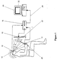
Figure 1 is a simplified block diagram of a preferred embodiment of a head tracking system; -
Figure 2 is an illustration of a preferred layout of a graphical user interface that may be incorporated within the preferred embodiment of the present invention; and -
Figure 3 is an example of a matrix used to associate a progressive addition lens type with a visual behavioural characteristic. - This preferred embodiment describes the use of a head tracking system that can be used in the method and system of the present invention for the dispensing and/or prescription of ophthalmic lenses. The main aim for the method and system of the preferred embodiment is thus to classify progressive lens wearers into progressive lens categories from which a particular progressive lens product can be dispensed.
- In brief, the head tracking system records the wearer's head position and visual stimulus (reading material) position during a set of visual tasks which are performed by the wearer. Preferably, the set of visual tasks includes a near task and an intermediate task.
- From the recorded head position and reading material position information, both visual ergonomics and eye movement data may be calculated, following which the data may be displayed and analysed such that the wearer can be categorised on the basis of head, eye and posture which is in turn used to recommend lens design, lens product categories, or frame and lens combinations. Preferably, the recommendation is presented in the form of a primary and a secondary recommendation wherein both recommendations comply with the wearer's progressive lens category but where each may differ on the basis of a parameter which is unrelated to the progressive lens category (for example, price).
- In general terms, the head tracking system preferably includes the following components:
- a. a wearer behavioural statistical model (database);
- b. a matrix of progressive lens categories associated with the wearer behavioural statistical model;
- c. head and reading material tracking hardware (herein referred to as the head tracking hardware);
- d. a computer device including display, keyboard and mouse; and
- e. customised application software.
- With reference to the wearer behaviour statistical model, the model preferably consists of a population sample of head and eye measurements. Preferably, the model is used to generate summary statistics of head turn, eye turn, head declination and eye declination for the near task, and head turn and eye turn for the intermediate task. The summary statistics are used to identify values which define the low, medium and high characterisations for each of these variables.
- Preferably, the values derived from the statistical analysis of the wearer behaviour statistical model are then used to define a set of classification ranges wherein each classification range is associated with a particular head and eye movement classification (for example, a high near eye declination classification range). The derived ranges may be incorporated into conditional tests within the customised application software, thus providing a mechanism for correlating empirical wearer visual behavioural parameters with a particular progressive addition lens category. The correlation between the empirical wearer visual behavioural parameters and a progressive addition lens category is presented in the form of a matrix, based on a predetermined relationship which will be described later.
- The head tracking hardware used is preferably a multi channel motion sensing system that can simultaneously track the position and attitude of multiple targets (for example, the wearer's head and the reading material). One example of a suitable motion sensing system is a Polhemus 'Fastrack' system (schematically illustrated in
Figure 1 ) which consists of atransmitter 10, tworeceivers interface unit 16. When placed in the proximity of thetransmitter 10 thereceivers interface unit 16 as the displacement between thetransmitter 10 and thereceivers - Attaching one of the
receivers 12 to a wearer's head makes the system a head tracking device, with azimuth being equated to head turn, elevation to head declination and roll to head tip. This is achieved by mounting thefirst receiver 12 on a known type of ophthalmic lens trial-frame 18 to be worn by the wearer during the trial. Thesecond receiver 14 is attached to a neartask reading plane 20 to separately provide an indication of the near task reading distance and near task reading plane angle. - Pursuant to the preferred form of the present invention, the
transmitter 10 is attached to an intermediatetask reading plane 22. - During a trial, head position and reading material position are recorded while the wearer performs the set of visual tasks. For such a trial, and in order to control for frame and lens effects, all wearer's ideally use a standard trial-
frame 18. - As indicated earlier, the set of visual tasks performed by the wearer includes a near task and an intermediate task. The near task consists of the wearer reading a particular arrangement of reading material on the near
task reading plane 20. Preferably, the purpose of the near task is to derive results for near eye turn and near eye declination from the empirical near task head and reading positional information. - Pursuant to the preferred form of the invention, the reading material used for the near task consists of a page containing three paragraphs of approximately equal proportions (W x h). Preferably, each paragraph is positioned in one of three distinct zones where each zone is vertically separated by a blank segment having a vertical dimension which exceeds the vertical dimension (h) of each paragraph. The distribution of the zones is such that one paragraph is located on the top of the reading material separated from a second paragraph in the middle which is in turn separated from a third paragraph which is located towards the bottom of the reading material.
- The intermediate task consists of the wearer reading a particular arrangement of reading material on the intermediate
task reading plane 22. Preferably, the intermediate task reading material consists of a known geometric arrangement of characters in the form of a rectangular matrix, which is wider than it is high. Preferably, the arrangement of the matrix is such that the characters are uniformly spaced, both vertically and horizontally. Preferably, the purpose of the intermediate task is to derive a result for intermediate eye turn from the empirical intermediate task head and reading material positional information. - During a reading task, signals from the head tracking
hardware receivers hardware interface unit 16 and are converted into a format suitable for transmission to a computer device via acommunications link 26. - With reference now to the computer device and the customised application software, the customised application software executable code preferably resides on a peripheral storage device fitted to the computer device. In operation, the customised application software executable code is activated and "run" on the computer device. In this operational mode, the combination of the computer device and the customised application software is referred to as the
programmed computer 28. - The programmed
computer 28 preferably provides functions which enable head tracking hardware interface unit communications and the sampling, recording, gathering processing and analysis of head and reading material position raw data. In addition, the programmedcomputer 28 may also provide a graphical user interface (GUI) 30 which is operable by a system operator. - Pursuant to a preferred form of the described apparatus, the
GUI 30 provides a system operator with an interactive "windows" environment for entering the wearer'sidentification 32 and background data, and for controlling system functions. Preferably, the wearer's background data will include information in relation to the wearer's prescription (sphere, cylinder and addition) 34, adescription 36 andsubjective wearer assessment 38 of any existing progressive addition lens already used by the wearer and any other data considered relevant and useful. - Preferably, the
GUI 30 provides interactive buttons and check boxes which are operable by the system operator to enable the selection of the desired reading task (near or intermediate) 40,recording control functions 42 and a recordedtask replay function 44. Ideally, theGUI 30 will also includes controls which are enabled subject to a conditional test. For example, theGUI 30 may include abutton 46 which is operable subsequent to the completion of the recording and processing of the near and intermediate tasks and which upon activation provides a primary and secondary recommendation for a lens type based on the recorded results. - The
GUI 30 preferably also incorporates graphical windows for the display of summary results 48 and a graphical representation of head and readingmaterial movements 50 during and subsequent to recording. - With particular reference to a preferred manner of sampling, recording, gathering and processing the wearer's head and reading material position raw data, subsequent to the enabling of the recording function, the programmed
computer 28 will preferably periodically sample and record raw data received from the head trackinghardware interface unit 16 via the communications link 26. The relevance of the raw data will be dependant upon the reading task. For the near task, the raw data will generally consist of at least 6 measures of 6 degrees of motion for at least two reference planes, one on the wearer's head the other on the near reading target. For the intermediate task, generally only the raw data which consists of 6 measures of 6 degrees of motion for the wearer's head reference plane will be relevant for the case of a Polhemus 'Fastrack' system where the transmitter reference plane is attached to the intermediate reading plane. - In the preferred form of the invention, the programmed
computer 28 processes near task data and intermediate task data according to the reading task. - For near task data, the programmed
computer 28 will preferably store data received from the head tracking hardware in two arrays, one for each of the head and reading material receiver position, and orientation data at least consisting of sampled x, y and z in absolute three dimensional space and azimuth, pitch and roll of the reference plane. - The programmed
computer 28 will preferably then filter the near task recorded data to exclude data not related to the reading task. The filtered data will preferably then be parsed to correlate segments of the filtered data with a particular paragraph of the near task reading material. Here, the programmedcomputer 28 utilises the wearer's head position and pitch data and reading material position and pitch data to compute a relative velocity of the wearer's projected line of sight relative to the near task reading material in the near task reading plane. High relative velocities, in the vicinity of the one third and two third sections of the filtered data are able to be interpreted by the programmedcomputer 28 as instants where the wearer traversed between the first and second and second and third paragraphs respectively. The programmedcomputer 28 preferably then partitions the filtered data into three data sets according to the identified high relative velocity boundary events whereby each set corresponds to a data record for a particular paragraph (i.e. upper, middle and lower paragraph data records). - The programmed
computer 28 may then calculate a mean near task reading distance (the mean distance between the near task reading plane mountedreceiver 14 and the head mounted receiver 12) and a maximum near task head rotation angle for each data record. - Preferably, the mean near task reading distance for each data record, is determined using a trigonometric calculation which includes the wearer's head mounted receiver position, the near task reading plane mounted receiver position and orientation, and the known geometry of the near task reading material. The mean near task reading distance calculation may also take into account a displacement between the wearer's eye position and the position of the head mounted
receiver 12. - The programmed
computer 28 preferably calculates the maximum near task head rotation angle for each data record using the standard deviation of the near task head turn (azimuth) data. - Subsequent to calculating the mean near task reading distance, the programmed
computer 28 is able to compute, for each data record, a head rotation angle required for the wearer to reach the end of a paragraph line without an eye rotation. - The programmed
computer 28 preferably then calculates, for each data record, an inferred near eye rotation as the difference between the maximum near task head rotation angle and the head rotation angle required for the wearer to reach the end of a line without an eye rotation. - The programmed
computer 28 preferably then calculates the mean of the three near task data records inferred near eye rotation results which is then taken as the final near eye turn result. - Near eye declination may be determined based upon the wearer's head declination and the relative position, orientation and geometry of the near task reading material. Here, the programmed
computer 28 is able to use the known geometric parameters of the near task reading material paragraphs, the measured position and orientation of the near task reading plane and the measured wearer's head declination to determine the angle (in the vertical plane) of each paragraph relative to the position of the wearer's head. - Subsequent to the calculation of the angle of each paragraph relative to the wearer's head, the programmed
computer 28 may then estimate the relative near eye declination for each paragraph as the difference between the relative paragraph angle and the measured head declination. - Preferably, the programmed
computer 28 calculates a mean near eye declination for each of the near task data records and derives a result from the set of mean results as a basis for the dispensing model. - With reference now to the processing of intermediate task data, only the head mounted
receiver 12 position data is of relevance. Pursuant to the preferred form of the invention, the purpose of the intermediate task is to classify the wearer in terms of intermediate eye turn. Hence, only intermediate head turn data will be processed by the programmedcomputer 28. Furthermore, unlike the near task, the intermediate data will preferably not be parsed to establish a correlation between intermediate reading material targets and eye turn, nor is start and end data discarded. - Preferably, intermediate eye turn will be calculated using an approach which is similar to that used for the determination of near eye turn. That is, the maximum head rotation angle will be determined and then subtracted from the head rotation angle required for the wearer to view characters at the beginning and ends of the intermediate reading material lines without an eye rotation. The difference between these angles may then be interpreted as the inferred intermediate eye rotation.
- Having described the principles underlying the processing of near task and intermediate task data, and the resultant derivation of the near and intermediate eye movement parameters, the step of associating the eye movement parameters with a particular progressive addition lens will now be described in detail.
- Here, the results of the near and intermediate task data processing are combined with the wearer's background data and compared to the standard model derived classification range for each relevant parameter. Preferably, the comparison is implemented using a series of conditional tests incorporated within the application software (for example, case statements). The result of the comparison enables the position of a relevant parameter within a classification range to be determined, thereby classifying the wearer into a particular vision behavioural category. The programmed computer then, by using a predetermined relationship, selects a progressive addition lens which most closely matches the wearer's vision behavioural category.
- With regard to such a predetermined relationship, and with particular reference to a relationship useful for a dispenser interested in progressive lens design choices, as with bi-focal lenses progressive lenses devote particular spatial locations on their surface to a particular viewing distance. Traditionally, the top of the progressive lens is for distance viewing while the bottom of the progressive lens is for near viewing, with a 'corridor' linking the two zones making a smooth transition between the zones. Unfortunately, it has not yet been possible to design a progressive surface without astigmatism or distortion flanking the viewing zones, although lens designers have been able to alter the viewing zone sizes and move the locations of the distortions around.
- For example, some wearers complain that they have to tilt their head back too far in order to be able to read text up close. The solution is to shorten the length of the progression zone, namely the corridor length. Other patients object to having to move their head from side to side to read because the size of the near zone is not wide enough before they encounter distortions. In this situation, the lens designer can widen the near zone.
- Clearly, if one can match the size, shape and location of the viewing zones of existing progressive lens designs to a wearer's typical eye movement patterns, as predicted on the basis of head and reading material movement or as directly measured with eye-tracking, a wearer will be more immediately satisfied. In the method and system of the present invention, progressive lens designs are preferably examined so as to match the zone locations and shapes as closely as possible to the expected patterns of usage of the lens surface.
- Alternatively, other lens measures may be examined that may correlate with, or that are known to correlate with, wearer satisfaction, that may be predicted on the basis of head and reading stimulus movement. For example, wearers with large head movements may need designs that minimise motion distortions that may cause visually induced nausea or 'swim'.
- It is examining and matching of this type that assists in the generation of a suitable predetermined relationship in the method and system of the present invention. In this respect, a sample matrix that may be used as the predetermined relationship is illustrated in
Figure 3. Figure 3 shows schematic lens plots of six progressive addition lenses (A to F). Each lens plot, bounded by a circle, has a cross representing the distance fitting point and a small circle representing the near power reference point. The curved lines flanking each lens represent the isoastigmatism contours that correspond to the limits of clear vision, or in other words represent the commencement of blur. Indeed, and as discussed above, astigmatism is often perceived by wearers as blur. These type of plots are used widely in the optical industry to compare lens designs. - The depicted designs vary systematically in two dimensions, namely in near zone width and corridor length. In relation to near zone width, the wider the separation between the isoastigmatism contours around the near reference circle, the larger the near zone area. In relation to corridor length, the further the distance between the distance and near reference points, the longer the corridor (ie, a wearer will have to rotate their eyes further down to reach the reading zone). Longer corridors generally afford lower peripheral astigmatism and distortion.
- Specifically, design A has a long corridor and a wide near zone; design B has a long corridor and a medium width near zone; design C has a long corridor and a narrow near zone; design D has a short corridor and a wide near zone; design E has a short corridor and a medium width near zone; and design F has a short corridor and a narrow near zone.
- With reference to these designs, a wearer who does not turn their head to read or rotate their eyes down would generally need a short corridor and a wide near zone, such as that in design D. On the other hand, a wearer who rotates their head a great deal while reading and rotates their eyes down would likely be satisfied with design C, thus taking advantage of the benefits associated not only with the more appropriate zone size and location but also the lower peripheral distortion.
- With regard now to the preferred operation of the head tracking system, in the preferred method of the invention, a system operator will initially ensure that the system is ready for use by powering on the system and performing system built in test functions. Subsequent to passing the system built in tests, the system operator will enter the wearer's identification and background data into the system and then position the wearer in a suitable position with respect to the system. A trial-frame will then be fitted to the wearer's head, which trial-frame includes a receiver module and a pair of lenses in accordance with the wearer's prescription for the given reading task distance. Preferably, the trial-frame uses single vision lenses, however, other lens types could also be used.
- The system operator will then request the wearer to adopt a head position whereby the wearer's line of sight is approximately parallel to the horizon. Furthermore, the system operator will ensure that the near task reading material is positioned flat on a desk or similar structure. The system operator will then enable a system calibration wherein positional information received from the head tracking hardware during the calibration step is decoded by the programmed computer and used to establish a set of reference coordinates.
- The system operator will then prompt the wearer to pick up the near task reading material, if they wish to, and commence reading. Subsequent to the receipt of an aural cue from the wearer indicating the start of the near task the system operator will enable the system recording control which initiates recording. In an alternative embodiment, the start of the reading task may be sensed by the system and used to start the recording process automatically.
- Head and reading material positional data will then be periodically sampled in 6 degrees of freedom and recorded for the duration of the near task by the programmed computer. During the recording process the system will provide the system operator with a graphical display of recorded head and reading material movements to provide an indication that the system is functioning correctly. The system operator will halt the recording process immediately following the receipt of a second aural cue from the wearer indicating completion of the near task. In an alternative embodiment, the.completion of the reading task may be sensed by the system and used to halt the recording process automatically.
- The system operator will then instruct the wearer to commence reading the intermediate task reading material. Once again, the system recording function is enabled and disabled by the system operator in response to aural cues from the wearer or automatically.
- Subsequent to the completion of the near, intermediate and any other relevant tasks, the system operator then instructs the programmed computer to save the recorded data and provide a primary and secondary recommendation for a progressive addition lens based on the recorded data. The receipt of the request to recommend a progressive addition lens triggers the programmed computer to process and analyse near and intermediate data as well as the wearer's background data in accordance with the methodology presented earlier. The result of the processing and analysis is a primary and secondary recommendation for a progressive addition lens.
- Finally, it will be understood that there may be other variations and modifications that may be made to the embodiments described herein that will also be within the scope of the present invention.
Claims (14)
- A system for prescribing and/or dispensing progressive ophthalmic lenses for a wearer, the progressive ophthalmic lenses including a distance viewing zone linked to a near viewing zone by a corridor zone, the system including:means for determining at least the wearer's individual visual behavioural patterns in terms of head movement and eye movement, wherein said means is adapted to determine the wearer's eye movement behavioural patterns based upon the wearer's head position and a reading material position and includes a programmed computer (28) in combination with a motion tracking system for recording head position and reading material position;wherein the programmed computer (28) is configured to process those patterns to categorize the wearer into a head and eye movement category and to recommend a progressive ophthalmic lens for the wearer corresponding to the wearer head and eye category based on a predetermined relationship between known head movement and eye movement characteristics and available progressive ophthalmic lenses.
- A system according to claim 1 wherein the programmed computer (28) is configured to categorize in combination with a wearer behavioural statistical model.
- A system according to claim 1, wherein the programmed computer (28) is configured to recommend in combination with a matrix of progressive ophthalmic lens categories associated with a wearer behavioural statistical model.
- A system according to claim 1 wherein the means for determining the wearer's individual visual behavioural patterns is adapted to determine the wearer's individual head movement behavioural patterns in terms of:a. near task head declination;b. near task head turn.c. intermediate task head turn; andd. intermediate task head declination.
- A system according to claim 1 wherein the means for determining at least the wearer's individual visual behavioural patterns in terms of head movement and eye movement is adapted to determine the wearer's eye movement behavioural patterns in terms of:a. near task eye turn;b. near task eye declination;c. intermediate task eye turn; andd. intermediate task eye declination.
- A system according to claim 1 wherein the programmed computer (28) is adapted to categorize wearers as either predominantly head movers or predominantly eye movers.
- A system according to claim 1, including means for generating a custom progressive ophthalmic lens design based on the recommended ophthalmic lens, and means for the manufacture of a custom progressive ophthalmic lens for the wearer from the custom progressive ophthalmic lens design.
- A method for prescribing and/or dispensing progressive ophthalmic lenses for a wearer, the progressive ophthalmic lenses including a distance viewing zone linked to a near viewing zone by a corridor zone, the method including the steps of:a. determining at least the wearer's individual visual behavioural patterns in terms of head movement and eye movement, wherein the wearer's eye movement behavioural patterns are determined based upon the wearer's head position and a reading material position, and wherein said determining step is performed by a programmed computer (28) in combination with a motion tracking system recording head position and reading material position; andb. processing those patterns to categorize the wearer into a head and eye movement category and to recommend a progressive ophthalmic lens for the wearer corresponding to the wearer head and eye movement category based on a predetermined relationship between known head movement and eye movement characteristics and available progressive ophthalmic lenses, wherein said processing step is performed by the programmed computer (28).
- A method according to claim 8 wherein categorizing the wearer into a head and eye movement category is performed by the programmed computer (28) in combination with a wearer behavioural statistical model.
- A method according to claim 8, wherein recommending a progressive ophthalmic lens for the wearer corresponding to the wearer head and eye movement category is performed by the programmed computer (28) in combination with a matrix of progressive ophthalmic lens categories associated with a wearer behavioural statistical model.
- A method according to claim 8 wherein the wearer's head movement behavioural patterns are expressed in terms of:a. near task head declination;b. near task head turn;c. intermediate task head turn; andd. intermediate task head declination.
- A method according to claim 8 wherein the wearer's eye movement behavioural patterns are expressed in terms of:a. near task eye turn;b. near task eye declination;c. intermediate task eye turn; andd. intermediate task eye declination.
- A method according to claim 8 wherein wearers are categorized as either predominantly head movers or predominantly eye movers.
- A method according to claim 8, including generating a custom progressive ophthalmic lens design based on the recommended progressive ophthalmic lens and manufacturing a custom progressive ophthalmic lens for the wearer from the custom progressive ophthalmic lens design.
Applications Claiming Priority (3)
| Application Number | Priority Date | Filing Date | Title |
|---|---|---|---|
| AUPQ5918A AUPQ591800A0 (en) | 2000-02-25 | 2000-02-25 | System for prescribing and/or dispensing ophthalmic lenses |
| AUPQ591800 | 2000-02-25 | ||
| PCT/AU2001/000198 WO2001062139A1 (en) | 2000-02-25 | 2001-02-23 | Method and system for prescribing and/or dispensing ophthalmic lenses |
Publications (3)
| Publication Number | Publication Date |
|---|---|
| EP1261273A1 EP1261273A1 (en) | 2002-12-04 |
| EP1261273A4 EP1261273A4 (en) | 2009-01-14 |
| EP1261273B1 true EP1261273B1 (en) | 2016-09-14 |
Family
ID=3820023
Family Applications (1)
| Application Number | Title | Priority Date | Filing Date |
|---|---|---|---|
| EP01907258.6A Expired - Lifetime EP1261273B1 (en) | 2000-02-25 | 2001-02-23 | Method and system for prescribing and/or dispensing ophthalmic lenses |
Country Status (8)
| Country | Link |
|---|---|
| US (1) | US6827443B2 (en) |
| EP (1) | EP1261273B1 (en) |
| JP (1) | JP5235047B2 (en) |
| AU (1) | AUPQ591800A0 (en) |
| BR (1) | BR0108570A (en) |
| CA (1) | CA2399247C (en) |
| MX (1) | MXPA02008234A (en) |
| WO (1) | WO2001062139A1 (en) |
Cited By (2)
| Publication number | Priority date | Publication date | Assignee | Title |
|---|---|---|---|---|
| EP4111256A1 (en) * | 2020-02-28 | 2023-01-04 | Essilor International | Apparatus for recommending an optical device |
| WO2024227576A1 (en) * | 2023-05-04 | 2024-11-07 | Essilor International | Calculation module configured to evaluate visual and postural ergonomics |
Families Citing this family (74)
| Publication number | Priority date | Publication date | Assignee | Title |
|---|---|---|---|---|
| US7066597B2 (en) * | 2001-12-05 | 2006-06-27 | Sola International Holdings Limited | Balanced progressive lens |
| AUPR958901A0 (en) | 2001-12-18 | 2002-01-24 | Telstra New Wave Pty Ltd | Information resource taxonomy |
| JP4124468B2 (en) * | 2002-10-08 | 2008-07-23 | Hoya株式会社 | Determination method of optical value of spectacle lens, spectacle lens manufacturing method, spectacle lens and ordering system thereof |
| AU2002953061A0 (en) * | 2002-11-20 | 2002-12-19 | Sola International Holdings Ltd | Method for designing progressive lenses |
| DE10313275A1 (en) * | 2003-03-24 | 2004-10-14 | Rodenstock Gmbh | Procedure for calculating an individual progressive lens |
| FR2863857B1 (en) * | 2003-12-23 | 2006-10-13 | Essilor Int | MEASURING THE BEHAVIOR OF AN OPHTHALMOLOGICAL LENS HOLDER |
| DE102004021407A1 (en) * | 2004-04-30 | 2005-11-17 | Rupp + Hubrach Gmbh & Co. Kg | gauge |
| ES2264848B1 (en) * | 2004-05-06 | 2008-01-01 | Indo Internacional, S.A. | PROCEDURE AND EQUIPMENT TO ESTABLISH THE VISUAL BEHAVIOR OF A PERSON, AND PROCEDURE FOR CUSTOMIZING A MOUNT LENS. |
| US7229173B2 (en) * | 2004-08-25 | 2007-06-12 | Essilor International (Compagnie Generale D'optique) S.A. | Short corridor progressive addition lenses with reduced unwanted astigmatism |
| WO2006054985A1 (en) * | 2004-11-16 | 2006-05-26 | Essilor International (Compagnie Generale D'optique) | Method for designing spectacle lenses taking into account an individual's head and eye movement |
| FR2880428B1 (en) * | 2005-01-04 | 2007-10-26 | Essilor Int | PROGRESSIVE OPHTHALMIC GLASS AND METHOD OF MANUFACTURING SUCH A GLASS |
| FR2885292B1 (en) * | 2005-05-03 | 2012-11-16 | Xavier Carriou | DEVICE FOR MEASURING THE TILT ANGLE OF THE HEAD AND THE ROTATION ANGLE OF THE EYE DURING READING |
| ZA200710463B (en) * | 2005-05-05 | 2009-03-25 | Carl Zeiss Vision Au Holding | An array of progressive opthalmic lens elements |
| FR2891375B1 (en) * | 2005-09-29 | 2008-02-15 | Essilor Int | POLARIZING OPHTHALMIC LENS ADAPTED TO THE BEHAVIOR EYE / HEAD OF A BEARER. |
| CA2626050C (en) | 2005-10-12 | 2015-12-08 | Carl Zeiss Vision Australia Holdings Limited | Ophthalmic lens element for myopia correction |
| FR2892529B1 (en) * | 2005-10-21 | 2008-02-01 | Interactif Visuel Systeme Ivs | SYSTEM FOR AIDING THE CORRECTION OF THE VIEW |
| CA2629906C (en) * | 2005-11-15 | 2015-09-29 | Carl Zeiss Vision Australia Holdings Limited | Ophthalmic lens design and/or dispensing |
| FR2894688B1 (en) * | 2005-12-13 | 2008-02-15 | Essilor Int | METHOD FOR DETERMINING A SET OF PROGRESSIVE MULTIFOCAL OPHTHALMIC LENSES |
| FR2894687B1 (en) * | 2005-12-13 | 2008-02-15 | Essilor Int | METHOD FOR DETERMINING A PROGRESSIVE OPHTHALMIC LENS |
| FR2898194B1 (en) * | 2006-03-01 | 2008-05-02 | Essilor Int | METHOD FOR DETERMINING A PROGRESSIVE OPHTHALMIC LENS |
| EP1882444A1 (en) * | 2006-07-28 | 2008-01-30 | Essilor International (Compagnie Generale D'optique) | Method and system to assess objectively visual characteristics |
| EP2629138A3 (en) * | 2006-10-10 | 2013-10-23 | Novartis AG | A contact lens for preventing myopia |
| FR2910645B1 (en) * | 2006-12-22 | 2009-07-03 | Essilor Int | METHOD FOR DETERMINING AN OPHTHALMIC LENS |
| FR2912820B1 (en) * | 2007-02-15 | 2009-05-15 | Essilor Int | REALIZATION OF AN OPHTHALMIC ELEMENT ADAPTED FOR FOVEAL AND PERIPHERAL VISIONS |
| FR2914173B1 (en) * | 2007-03-30 | 2010-02-26 | Essilor Int | METHOD OF MEASURING THE POSITION FOLLOWING A HORIZONTAL DIRECTION OF THE SAGITTAL PLAN OF A REMARKABLE POINT OF AN EYE OF A SUBJECT |
| FR2920888B1 (en) * | 2007-09-12 | 2010-10-15 | Essilor Int | REALIZING AN OPHTHALMIC GLASS FOR A BEARER |
| FR2928745B1 (en) * | 2008-03-14 | 2012-03-02 | Essilor Int | REALIZATION OF A NEW GLASS OF PROGRESSIVE GLASSES. |
| JP4609581B2 (en) * | 2008-03-26 | 2011-01-12 | セイコーエプソン株式会社 | Simulation device, simulation program, and recording medium recording simulation program |
| FR2932577B1 (en) * | 2008-06-12 | 2010-08-27 | Essilor Int | PERFORMING A PERSONALIZED PROGRESSIVE OPHTHALMIC GLASS |
| EP2198769A1 (en) * | 2008-12-22 | 2010-06-23 | Essilor International (Compagnie Générale D'Optique) | A method of and an apparatus for simulating an optical effect of an optical lens |
| JP5187227B2 (en) * | 2009-02-23 | 2013-04-24 | セイコーエプソン株式会社 | Eyeglass lens design method |
| DE102009025215B4 (en) | 2009-06-17 | 2025-03-27 | Carl Zeiss Vision International Gmbh | Method and device for determining centering data |
| JP2011048321A (en) | 2009-07-30 | 2011-03-10 | Seiko Epson Corp | Downward eyeball movement-measuring jig, jig affixing device, and downward eyeball movement measuring method |
| JP5351691B2 (en) | 2009-10-01 | 2013-11-27 | ホーヤ レンズ マニュファクチャリング フィリピン インク | Eyeball downward amount measuring device and eyeball downward amount measuring method |
| FR2950983A1 (en) * | 2009-10-01 | 2011-04-08 | Essilor Int | METHOD FOR DETERMINING, OPTIMIZING AND MANUFACTURING OPHTHALMIC LENS AND OPHTHALMIC LENS ASSEMBLY |
| JP5415233B2 (en) * | 2009-11-13 | 2014-02-12 | ホーヤ レンズ マニュファクチャリング フィリピン インク | Design method and manufacturing method of spectacle lens |
| JP2011138064A (en) | 2009-12-29 | 2011-07-14 | Seiko Epson Corp | Vision shift amount measuring method and vision shift amount measuring jig |
| JP5725646B2 (en) * | 2010-03-10 | 2015-05-27 | ホーヤ レンズ マニュファクチャリング フィリピン インク | Progressive power lens design method, progressive power lens design system, and progressive power lens manufacturing method |
| JP2011209530A (en) | 2010-03-30 | 2011-10-20 | Seiko Epson Corp | Wearing condition parameter measurement device for spectacle lens and wearing condition parameter measurement method for spectacle lens |
| JP2011253042A (en) | 2010-06-02 | 2011-12-15 | Seiko Epson Corp | Selection method for spectacle lens and selection system for spectacle lens |
| FR2962817B1 (en) * | 2010-07-15 | 2013-04-26 | Ergoptic | ENVIRONMENTAL ACTIVITY CONFIGURATION SIMULATION DEVICE AND PROGRESSIBLE GLASS CHOICE ASSISTANCE METHOD |
| EP2648032A1 (en) * | 2012-04-02 | 2013-10-09 | Essilor Canada Ltee | Progressive ophthalmic surface |
| DE102012014399A1 (en) * | 2012-07-20 | 2014-05-15 | Carl Zeiss Vision International Gmbh | Device for determining and outputting a spectacle lens type suitable for a spectacle wearer |
| US8814361B2 (en) * | 2012-07-30 | 2014-08-26 | New Jersey Institute Of Technology | Method for determining the acceptance of progressive addition lenses |
| EP2695578B1 (en) * | 2012-08-07 | 2015-09-16 | Essilor Canada Ltee | A method for determining eye and head movements of an individual |
| KR101300670B1 (en) | 2012-11-14 | 2013-08-27 | (주)뷰아이텍 | Method for measuring of eye rotation and calculation length of corridor in progressive lenses and it's device for implementation |
| US9265458B2 (en) | 2012-12-04 | 2016-02-23 | Sync-Think, Inc. | Application of smooth pursuit cognitive testing paradigms to clinical drug development |
| US9380976B2 (en) | 2013-03-11 | 2016-07-05 | Sync-Think, Inc. | Optical neuroinformatics |
| EP2833196B1 (en) * | 2013-08-02 | 2016-03-16 | ESSILOR INTERNATIONAL (Compagnie Générale d'Optique) | A method of controlling a programmable ophthalmic lens device |
| CN103445758A (en) * | 2013-08-30 | 2013-12-18 | 浙江理工大学 | Eyesight testing system based on wireless communication |
| US9448421B2 (en) | 2013-09-04 | 2016-09-20 | Johnson & Johnson Vision Care, Inc. | Ophthalmic lens system capable of communication between lenses utilizing a secondary external device |
| US9936916B2 (en) * | 2013-10-09 | 2018-04-10 | Nedim T. SAHIN | Systems, environment and methods for identification and analysis of recurring transitory physiological states and events using a portable data collection device |
| JP6220627B2 (en) * | 2013-10-17 | 2017-10-25 | 株式会社ニコン・エシロール | Measurement method, spectacle lens selection method, spectacle lens design method, spectacle lens manufacturing method, and measurement apparatus |
| FR3013132B1 (en) * | 2013-11-08 | 2017-01-20 | Essilor Int | METHOD FOR DETERMINING AT LEAST ONE OPTICAL DESIGN PARAMETER FOR A PROGRESSIVE OPHTHALMIC LENS |
| FR3018120B1 (en) | 2014-02-28 | 2018-07-27 | Essilor International | METHOD AND DEVICE FOR SELECTING AN EQUIPMENT COMPRISING AT LEAST ONE OPHTHALMIC GLASS AND A MOUNTING, METHOD AND DEVICE FOR ACCOMPANYING THE CHOICE OF SUCH AN EQUIPMENT |
| EP3332286B1 (en) * | 2015-08-03 | 2019-07-03 | Essilor International | A method for determining the optical power of an optical lens |
| WO2017042612A1 (en) * | 2015-09-12 | 2017-03-16 | Shamir Optical Industry Ltd. | Automatic eyewear measurement and specification |
| DE102015219868B4 (en) * | 2015-10-13 | 2019-02-21 | Carl Zeiss Vision International Gmbh | System and method for training head movements |
| EP3362845B1 (en) * | 2015-10-15 | 2025-08-06 | Essilor International | Method for determining an optical system of a progressive lens |
| US10018854B2 (en) | 2016-06-22 | 2018-07-10 | Indizen Optical Technologies of America, LLC | Custom ophthalmic lens design derived from multiple data sources |
| US11185235B2 (en) * | 2017-03-27 | 2021-11-30 | Panasonic Intellectual Property Management Co., Ltd. | Information processing method, information processing device, and recording medium |
| EP3451049B8 (en) * | 2017-08-31 | 2025-05-07 | Essilor International | Method and system for determining an optical system intended to equip a person on the basis of the adaptability of the person to a visual modification of his/her environment |
| EP3501376A1 (en) | 2017-12-22 | 2019-06-26 | Essilor International | Methods and systems for determining a refraction of at least an eye of a person |
| EP3598210A1 (en) * | 2018-07-18 | 2020-01-22 | Essilor International | Method for determining an ophthalmic component |
| EP3598208B1 (en) * | 2018-07-18 | 2025-02-12 | Essilor International | Method for determining a component of an ophthalmic equipment and associated system |
| EP3598209A1 (en) * | 2018-07-18 | 2020-01-22 | Essilor International | Method for determining an opththalmic equipment and system associated |
| GB2576910B (en) * | 2018-09-06 | 2021-10-20 | Sony Interactive Entertainment Inc | User profile generating system and method |
| US12092903B2 (en) | 2018-10-09 | 2024-09-17 | Essilor International | Method for adapting ophthalmic equipment according to a wearers visual exploration strategy |
| CN113613547B (en) * | 2019-03-22 | 2024-09-13 | 依视路国际公司 | Apparatus and method for evaluating the performance of a visual device for a visual task |
| CN113508331B (en) * | 2019-03-29 | 2023-12-15 | 豪雅镜片泰国有限公司 | Method for measuring rotation characteristics of eyeball of subject and method for designing progressive power lens |
| CN111820859A (en) * | 2019-04-22 | 2020-10-27 | 厦门立达信照明有限公司 | Vision testing equipment and method |
| WO2020260481A1 (en) * | 2019-06-26 | 2020-12-30 | Essilor International | Head freedom area of an optical lens |
| JP7558017B2 (en) * | 2020-09-30 | 2024-09-30 | ホヤ レンズ タイランド リミテッド | PROGRESSIVE ADDITION LENS DESIGN METHOD, DETERMINATION METHOD, MANUFACTURING METHOD, AND DESIGN SYSTEM |
| JP7544552B2 (en) * | 2020-09-30 | 2024-09-03 | ホヤ レンズ タイランド リミテッド | Method for determining visual behavior, method for designing and manufacturing progressive power lens, and system for designing progressive power lens |
Family Cites Families (22)
| Publication number | Priority date | Publication date | Assignee | Title |
|---|---|---|---|---|
| US3737217A (en) * | 1971-07-06 | 1973-06-05 | Nasa | Visual examination apparatus |
| US4961640A (en) * | 1982-08-20 | 1990-10-09 | Irlen Helen L | Method and apparatus of treatment of symptoms of the Irlen syndrom |
| US4656590A (en) | 1984-11-07 | 1987-04-07 | Ronald Ace | Method and apparatus for making patterns for eyeglasses |
| US4856891A (en) * | 1987-02-17 | 1989-08-15 | Eye Research Institute Of Retina Foundation | Eye fundus tracker/stabilizer |
| JPH04288121A (en) * | 1991-03-18 | 1992-10-13 | A T R Shichiyoukaku Kiko Kenkyusho:Kk | Line-of-sight detector |
| DE4143433C2 (en) | 1991-07-19 | 1995-02-16 | Preusner Paul Rolf Dipl Phys D | Automatic, subjectively controlled refraction device |
| GB9210981D0 (en) | 1992-05-22 | 1992-07-08 | Eyelab Ltd | Vision testing apparatus |
| US5329322A (en) * | 1992-05-26 | 1994-07-12 | Yancey Don R | Palm size autorefractor and fundus topographical mapping instrument |
| US5345281A (en) | 1992-12-17 | 1994-09-06 | John Taboada | Eye tracking system and method |
| JP2588219Y2 (en) * | 1993-01-08 | 1999-01-06 | ホーヤ株式会社 | Eyeglass lens selection table |
| JPH0742625U (en) * | 1993-12-29 | 1995-08-11 | ホーヤ株式会社 | Eyeglass lens selection table |
| FR2719988B1 (en) | 1994-05-20 | 1996-08-02 | Centre Nat Rech Scient | Eye movement control device. |
| JP3558144B2 (en) * | 1995-11-24 | 2004-08-25 | 株式会社トプコン | Eye point measuring device when wearing eyeglass frames |
| JPH1014882A (en) * | 1996-07-02 | 1998-01-20 | Nippon Telegr & Teleph Corp <Ntt> | Non-contact gaze measurement device |
| JP3944914B2 (en) * | 1996-10-14 | 2007-07-18 | セイコーエプソン株式会社 | Manufacturing method of progressive multifocal lens |
| US5777719A (en) * | 1996-12-23 | 1998-07-07 | University Of Rochester | Method and apparatus for improving vision and the resolution of retinal images |
| JP2953446B2 (en) | 1997-10-17 | 1999-09-27 | 株式会社ニデック | Subjective optometer |
| US6027216A (en) * | 1997-10-21 | 2000-02-22 | The Johns University School Of Medicine | Eye fixation monitor and tracker |
| AUPP046997A0 (en) | 1997-11-19 | 1997-12-18 | Carl Gasper & Associates Pty Ltd | Magnification test apparatus |
| JP2000020580A (en) * | 1998-07-02 | 2000-01-21 | Fine System Kikaku Kk | Eyeglass layout and lens selection work support system |
| JP2000020703A (en) * | 1998-07-02 | 2000-01-21 | Fine System Kikaku Kk | Glasses compatible shooting device |
| US6090051A (en) * | 1999-03-03 | 2000-07-18 | Marshall; Sandra P. | Method and apparatus for eye tracking and monitoring pupil dilation to evaluate cognitive activity |
-
2000
- 2000-02-25 AU AUPQ5918A patent/AUPQ591800A0/en not_active Abandoned
-
2001
- 2001-02-23 MX MXPA02008234A patent/MXPA02008234A/en active IP Right Grant
- 2001-02-23 BR BR0108570-0A patent/BR0108570A/en not_active Application Discontinuation
- 2001-02-23 US US10/181,988 patent/US6827443B2/en not_active Expired - Lifetime
- 2001-02-23 CA CA002399247A patent/CA2399247C/en not_active Expired - Lifetime
- 2001-02-23 WO PCT/AU2001/000198 patent/WO2001062139A1/en not_active Ceased
- 2001-02-23 JP JP2001561211A patent/JP5235047B2/en not_active Expired - Lifetime
- 2001-02-23 EP EP01907258.6A patent/EP1261273B1/en not_active Expired - Lifetime
Non-Patent Citations (1)
| Title |
|---|
| AFANADOR AJ., AITSEBAOMO P: "The range of eye movements through progressive multifocals", OPTOMETRIC MONTHLY, vol. 73, February 1982 (1982-02-01), pages 82 - 87 * |
Cited By (2)
| Publication number | Priority date | Publication date | Assignee | Title |
|---|---|---|---|---|
| EP4111256A1 (en) * | 2020-02-28 | 2023-01-04 | Essilor International | Apparatus for recommending an optical device |
| WO2024227576A1 (en) * | 2023-05-04 | 2024-11-07 | Essilor International | Calculation module configured to evaluate visual and postural ergonomics |
Also Published As
| Publication number | Publication date |
|---|---|
| JP5235047B2 (en) | 2013-07-10 |
| WO2001062139A1 (en) | 2001-08-30 |
| US6827443B2 (en) | 2004-12-07 |
| MXPA02008234A (en) | 2004-09-10 |
| EP1261273A1 (en) | 2002-12-04 |
| BR0108570A (en) | 2002-11-19 |
| AUPQ591800A0 (en) | 2000-03-23 |
| CA2399247C (en) | 2009-04-14 |
| US20030107707A1 (en) | 2003-06-12 |
| EP1261273A4 (en) | 2009-01-14 |
| CA2399247A1 (en) | 2001-08-30 |
| JP2003523244A (en) | 2003-08-05 |
Similar Documents
| Publication | Publication Date | Title |
|---|---|---|
| CA2399247C (en) | Method and system for prescribing and/or dispensing ophthalmic lenses | |
| US7287853B2 (en) | Spectacle and contact lens selecting system and method thereof | |
| US6592223B1 (en) | System and method for optimal viewing of computer monitors to minimize eyestrain | |
| US8322855B2 (en) | Method for determining the visual behaviour of a Person | |
| US20080189173A1 (en) | Vision Center Kiosk | |
| CN102165362B (en) | Method for designing eyeglass lens | |
| US9182208B2 (en) | Method of selecting kind of size of a helmet and shape of a pad, method of adjusting helmet size by using the selection method, and head size measuring tool used in aforesaid selection method | |
| CN120338933B (en) | AR intelligent shopping guide interaction method and system applied to store management | |
| EP3539459B1 (en) | Apparatus and method for ascertaining a type of spectacle lens and apparatus and method for determining a refractive power distribution of progressive spectacle lens | |
| US20180032816A1 (en) | Fixation identification using density optimization | |
| EP3655815B1 (en) | A method for determining a postural and visual behavior of a person | |
| US10401653B2 (en) | Method and device for aiding the choice of a piece of equipment comprising at least one ophthalmic lens and a frame, method and device for selecting such a piece of equipment | |
| AU780479B2 (en) | Method and system for prescribing and/or dispensing ophthalmic lenses | |
| US20170181617A1 (en) | Method of visual testing of an individual and associated device | |
| CN109661607A (en) | Method for determining the customized vision compensation gradual change Ophthalmoligic instrument of individual | |
| US20050029021A1 (en) | Cold-flame propulsion system | |
| CN106963384A (en) | A kind of Compensatory Head Posture detection method and device | |
| US12169927B2 (en) | System and a method for alerting on vision impairment | |
| EP4512304A2 (en) | Determining a lens shape for producing an optical lens for an eye of a person | |
| EP4011273A1 (en) | Method and device for determining at least one astigmatic effect of at least one eye | |
| CN122056546A (en) | A method, device, terminal equipment and system for detecting visual fatigue |
Legal Events
| Date | Code | Title | Description |
|---|---|---|---|
| PUAI | Public reference made under article 153(3) epc to a published international application that has entered the european phase |
Free format text: ORIGINAL CODE: 0009012 |
|
| 17P | Request for examination filed |
Effective date: 20020924 |
|
| AK | Designated contracting states |
Kind code of ref document: A1 Designated state(s): AT BE CH CY DE DK ES FI FR GB GR IE IT LI LU MC NL PT SE TR |
|
| AX | Request for extension of the european patent |
Free format text: AL;LT;LV;MK;RO;SI |
|
| RAP1 | Party data changed (applicant data changed or rights of an application transferred) |
Owner name: CARL ZEISS VISION AUSTRALIA HOLDINGS LTD. |
|
| A4 | Supplementary search report drawn up and despatched |
Effective date: 20081217 |
|
| 17Q | First examination report despatched |
Effective date: 20090325 |
|
| REG | Reference to a national code |
Ref country code: DE Ref legal event code: R079 Ref document number: 60150109 Country of ref document: DE Free format text: PREVIOUS MAIN CLASS: A61B0003032000 Ipc: A61B0005110000 |
|
| GRAP | Despatch of communication of intention to grant a patent |
Free format text: ORIGINAL CODE: EPIDOSNIGR1 |
|
| INTG | Intention to grant announced |
Effective date: 20160421 |
|
| RIC1 | Information provided on ipc code assigned before grant |
Ipc: G02C 7/02 20060101ALI20160412BHEP Ipc: A61B 5/11 20060101AFI20160412BHEP |
|
| GRAS | Grant fee paid |
Free format text: ORIGINAL CODE: EPIDOSNIGR3 |
|
| GRAA | (expected) grant |
Free format text: ORIGINAL CODE: 0009210 |
|
| AK | Designated contracting states |
Kind code of ref document: B1 Designated state(s): AT BE CH CY DE DK ES FI FR GB GR IE IT LI LU MC NL PT SE TR |
|
| REG | Reference to a national code |
Ref country code: GB Ref legal event code: FG4D |
|
| REG | Reference to a national code |
Ref country code: CH Ref legal event code: EP |
|
| REG | Reference to a national code |
Ref country code: IE Ref legal event code: FG4D |
|
| REG | Reference to a national code |
Ref country code: AT Ref legal event code: REF Ref document number: 828010 Country of ref document: AT Kind code of ref document: T Effective date: 20161015 |
|
| REG | Reference to a national code |
Ref country code: DE Ref legal event code: R096 Ref document number: 60150109 Country of ref document: DE |
|
| REG | Reference to a national code |
Ref country code: NL Ref legal event code: MP Effective date: 20160914 |
|
| PG25 | Lapsed in a contracting state [announced via postgrant information from national office to epo] |
Ref country code: FI Free format text: LAPSE BECAUSE OF FAILURE TO SUBMIT A TRANSLATION OF THE DESCRIPTION OR TO PAY THE FEE WITHIN THE PRESCRIBED TIME-LIMIT Effective date: 20160914 |
|
| REG | Reference to a national code |
Ref country code: AT Ref legal event code: MK05 Ref document number: 828010 Country of ref document: AT Kind code of ref document: T Effective date: 20160914 |
|
| REG | Reference to a national code |
Ref country code: FR Ref legal event code: PLFP Year of fee payment: 17 |
|
| PG25 | Lapsed in a contracting state [announced via postgrant information from national office to epo] |
Ref country code: NL Free format text: LAPSE BECAUSE OF FAILURE TO SUBMIT A TRANSLATION OF THE DESCRIPTION OR TO PAY THE FEE WITHIN THE PRESCRIBED TIME-LIMIT Effective date: 20160914 Ref country code: SE Free format text: LAPSE BECAUSE OF FAILURE TO SUBMIT A TRANSLATION OF THE DESCRIPTION OR TO PAY THE FEE WITHIN THE PRESCRIBED TIME-LIMIT Effective date: 20160914 Ref country code: GR Free format text: LAPSE BECAUSE OF FAILURE TO SUBMIT A TRANSLATION OF THE DESCRIPTION OR TO PAY THE FEE WITHIN THE PRESCRIBED TIME-LIMIT Effective date: 20161215 Ref country code: ES Free format text: LAPSE BECAUSE OF FAILURE TO SUBMIT A TRANSLATION OF THE DESCRIPTION OR TO PAY THE FEE WITHIN THE PRESCRIBED TIME-LIMIT Effective date: 20160914 |
|
| PG25 | Lapsed in a contracting state [announced via postgrant information from national office to epo] |
Ref country code: PT Free format text: LAPSE BECAUSE OF FAILURE TO SUBMIT A TRANSLATION OF THE DESCRIPTION OR TO PAY THE FEE WITHIN THE PRESCRIBED TIME-LIMIT Effective date: 20170116 Ref country code: AT Free format text: LAPSE BECAUSE OF FAILURE TO SUBMIT A TRANSLATION OF THE DESCRIPTION OR TO PAY THE FEE WITHIN THE PRESCRIBED TIME-LIMIT Effective date: 20160914 Ref country code: BE Free format text: LAPSE BECAUSE OF FAILURE TO SUBMIT A TRANSLATION OF THE DESCRIPTION OR TO PAY THE FEE WITHIN THE PRESCRIBED TIME-LIMIT Effective date: 20160914 |
|
| REG | Reference to a national code |
Ref country code: DE Ref legal event code: R097 Ref document number: 60150109 Country of ref document: DE |
|
| PG25 | Lapsed in a contracting state [announced via postgrant information from national office to epo] |
Ref country code: IT Free format text: LAPSE BECAUSE OF FAILURE TO SUBMIT A TRANSLATION OF THE DESCRIPTION OR TO PAY THE FEE WITHIN THE PRESCRIBED TIME-LIMIT Effective date: 20160914 |
|
| PLBE | No opposition filed within time limit |
Free format text: ORIGINAL CODE: 0009261 |
|
| STAA | Information on the status of an ep patent application or granted ep patent |
Free format text: STATUS: NO OPPOSITION FILED WITHIN TIME LIMIT |
|
| PG25 | Lapsed in a contracting state [announced via postgrant information from national office to epo] |
Ref country code: DK Free format text: LAPSE BECAUSE OF FAILURE TO SUBMIT A TRANSLATION OF THE DESCRIPTION OR TO PAY THE FEE WITHIN THE PRESCRIBED TIME-LIMIT Effective date: 20160914 |
|
| 26N | No opposition filed |
Effective date: 20170615 |
|
| PG25 | Lapsed in a contracting state [announced via postgrant information from national office to epo] |
Ref country code: MC Free format text: LAPSE BECAUSE OF FAILURE TO SUBMIT A TRANSLATION OF THE DESCRIPTION OR TO PAY THE FEE WITHIN THE PRESCRIBED TIME-LIMIT Effective date: 20160914 |
|
| REG | Reference to a national code |
Ref country code: CH Ref legal event code: PL |
|
| PG25 | Lapsed in a contracting state [announced via postgrant information from national office to epo] |
Ref country code: LI Free format text: LAPSE BECAUSE OF NON-PAYMENT OF DUE FEES Effective date: 20170228 Ref country code: CH Free format text: LAPSE BECAUSE OF NON-PAYMENT OF DUE FEES Effective date: 20170228 |
|
| REG | Reference to a national code |
Ref country code: IE Ref legal event code: MM4A |
|
| PG25 | Lapsed in a contracting state [announced via postgrant information from national office to epo] |
Ref country code: LU Free format text: LAPSE BECAUSE OF NON-PAYMENT OF DUE FEES Effective date: 20170223 |
|
| REG | Reference to a national code |
Ref country code: FR Ref legal event code: PLFP Year of fee payment: 18 |
|
| PG25 | Lapsed in a contracting state [announced via postgrant information from national office to epo] |
Ref country code: IE Free format text: LAPSE BECAUSE OF NON-PAYMENT OF DUE FEES Effective date: 20170223 |
|
| PG25 | Lapsed in a contracting state [announced via postgrant information from national office to epo] |
Ref country code: CY Free format text: LAPSE BECAUSE OF NON-PAYMENT OF DUE FEES Effective date: 20160914 |
|
| PG25 | Lapsed in a contracting state [announced via postgrant information from national office to epo] |
Ref country code: TR Free format text: LAPSE BECAUSE OF FAILURE TO SUBMIT A TRANSLATION OF THE DESCRIPTION OR TO PAY THE FEE WITHIN THE PRESCRIBED TIME-LIMIT Effective date: 20160914 |
|
| PGFP | Annual fee paid to national office [announced via postgrant information from national office to epo] |
Ref country code: DE Payment date: 20200219 Year of fee payment: 20 Ref country code: GB Payment date: 20200219 Year of fee payment: 20 |
|
| PGFP | Annual fee paid to national office [announced via postgrant information from national office to epo] |
Ref country code: FR Payment date: 20200219 Year of fee payment: 20 |
|
| REG | Reference to a national code |
Ref country code: DE Ref legal event code: R071 Ref document number: 60150109 Country of ref document: DE |
|
| REG | Reference to a national code |
Ref country code: GB Ref legal event code: PE20 Expiry date: 20210222 |
|
| PG25 | Lapsed in a contracting state [announced via postgrant information from national office to epo] |
Ref country code: GB Free format text: LAPSE BECAUSE OF EXPIRATION OF PROTECTION Effective date: 20210222 |