EP1261225A2 - Communication channel set up method and communication control device for reducing interference between radio communication systems - Google Patents
Communication channel set up method and communication control device for reducing interference between radio communication systems Download PDFInfo
- Publication number
- EP1261225A2 EP1261225A2 EP02011537A EP02011537A EP1261225A2 EP 1261225 A2 EP1261225 A2 EP 1261225A2 EP 02011537 A EP02011537 A EP 02011537A EP 02011537 A EP02011537 A EP 02011537A EP 1261225 A2 EP1261225 A2 EP 1261225A2
- Authority
- EP
- European Patent Office
- Prior art keywords
- frequency
- communication system
- radio communication
- frequency band
- radio
- Prior art date
- Legal status (The legal status is an assumption and is not a legal conclusion. Google has not performed a legal analysis and makes no representation as to the accuracy of the status listed.)
- Granted
Links
Images


Classifications
-
- H—ELECTRICITY
- H04—ELECTRIC COMMUNICATION TECHNIQUE
- H04W—WIRELESS COMMUNICATION NETWORKS
- H04W16/00—Network planning, e.g. coverage or traffic planning tools; Network deployment, e.g. resource partitioning or cells structures
- H04W16/14—Spectrum sharing arrangements between different networks
Definitions
- the present invention relates to a communication channel set up method and a communication control device, and more particularly, to a communication channel set up method and a communication control device for reducing interferences between radio communication systems using radio signals of close frequencies.
- the spurious components such as higher harmonic components of the carrier component, the intermodulation distortion components, etc., are generated due to the non-linearity of the amplifier, etc.
- spurious components are generated in a frequency region largely separated from the carrier frequency such that they become components outside the frequency band that can be used by that system.
- a communication channel set up method for setting up a communication channel to be used by a second radio communication system that can use a second frequency band close to a first frequency band that can be used by a first radio communication system, comprising: detecting a utilization state of a prescribed frequency in the first frequency band that can cause interferences to the first radio communication system when a communication channel of a particular frequency in the second frequency band is used by the second radio communication system; and allocating a communication channel other than that of the particular frequency to the second radio communication system when the prescribed frequency in the first frequency band is currently used by the first radio communication system.
- a communication control device for controlling a communication channel to be used by a second radio communication system that can use a second frequency band close to a first frequency band that can be used by a first radio communication system, comprising: a detection unit configured to detect a utilization state of a prescribed frequency in the first frequency band that can cause interferences to the first radio communication system when a communication channel of a particular frequency in the second frequency band is used by the second radio communication system; and an allocation unit configured to allocate a communication channel other than that of the particular frequency to the second radio communication system when the prescribed frequency in the first frequency band is currently used by the first radio communication system.
- Fig. 1 to Fig. 8 one embodiment of a communication channel set up method and a communication control device according to the present invention will be described in detail.
- the radio communication device is applicable to a radio communication system around which other radio communication systems are operated at close frequency bands.
- This radio communication system 1 has a base station 10 for providing a communication service and a mobile terminal device 20 for utilizing the communication service provided by this base station 10, as shown in Fig. 1, for example.
- This radio comutunication sysrem 1 is used under an environment in which another radio communication system 2 having a base station 30 and a mobile terminal device 40 that are using radio signals of a frequency close to that of the radio communication system 1
- the base station 10 of the radio communication system 1 has a potentially interferred frequency receiving unit 11 for receiving radio signals of a frequency that can be used by the radio communication system 2, a memory unit 12 for storing a strength of radio signals received by the potentially interferred frequency receiving unit 11, a comparison unit 13 for comparing the radio signal strength stored in the memory unit 12, a judgement unit 14 for Judging a state of radio signal use by the radio communication system 2 according to a comparison result obtained by the comparison unit 13, a radio unit for carrying out radio communications with the mobile terminal device 20, and a control unit 16 for executing a control of a communication channel to be used by the radio unit 15 according to a judgement result obtained by the judgement unit 14.
- the radio unit 15 has a radio channel set up unit 15a for carrying out a set up of a communication channel to be used between the base station 10 and the mobile terminal device 20 according to a command from the control unit 16, a carrier generation unit 15b for generating carriers of a frequency according to a command from the radio channel set up unit 15a, a modulation unit 15c for modulating the carriers generated by the carrier generation unit 15b by using a baseband signal according to the transmission data, and an RF (Radio Frequency) amplifier 15d for amplifying an output of the modulation unit 15c.
- RF Radio Frequency
- the radio communication system 1 is a portable telephone system known as PHS (Personal Handyphone System) that uses 1.9 GHz band radio signals, as indicated in Fig. 2, for example.
- This radio communication system 1 uses a multi-carrier TDMA (Time Division Multiple Access) scheme in order to carry out communications of a plurality of channels. In this scheme, 300 KHz band per one carrier, for example. For this reason, a plurality (m) of carriers are provided in a frequency band 100 that can be used by this radio communication system 1.
- TDMA Time Division Multiple Access
- the radio communication system 2 is a portable telephone system of IMT-2000 scheme that uses radio signals of 2 GHz band (uplink: 1.92-1.98 GHz, downlink: 2.11-2.17 GHz), as indicated in Fig. 2, for example.
- This radio communication system 2 uses a CDMA (Code Division Multiple Access) scheme in order to carry out communications of a plurality of channels within a 5MHz band, for example.
- a plurality of 5 MHz bands can be provided for each service provider of the radio communication system 2, for example.
- the so called guard band 130 of about 5 MHz is provided, as indicated in Fig. 2, for example.
- the spurious components such as higher harmonic components of the carrier component (Fig. 3), the intermodulation distortion components (Fig. 4), etc., are generated due to the non-linearity of the amplifier, etc. For this reason, there are cases where such spurious components are generated from the base station 10 and the mobile terminal device 20 constituting the radio communication system 1. For example, at the base station 10, the spurious components are generated at the RF amplifier 15d. Some of the spurious components have the strength which becomes stronger for a frequency closer to that of the carriers which can possibly cause interferences to a part (potentially interferred frequency band) 111 of the uplink frequency band 110.
- a frequency of the spurious component is in a certain relationship with a generation frequency of the carrier generation unit 15b in the case of the base station 10, for example, so that a frequency on the radio communication 2 side that can possibly be interfered when the communication channel of a specific frequency is used at the radio communication system 1 (potentially interferred frequency) can be predicted in advance.
- the interferring frequency band 102 that can influence the radio communication system 2 side by the spurious components are known in advance, as indicated in Fig. 2, for example.
- the presence or absence of the use of the potentially interferred frequency band 111 at the radio communication system 2 side is judged according to the radio signals received by the potentially interferred frequency receiving unit 11 shown in Fig. 1.
- the frequency received by this potentially interferred frequency receiving unit 11 may be the potentially interferred frequency band 111 itself.
- the receiving level at the potentially interferred frequency receiving unit 11 of the radio signals of the uplink frequency transmitted from the mobile terminal device 40 becomes low as they are blocked by the building depending on the location of the moblle terminal device 40. For this reason, if the presence or absence of the use of the potentially interferred frequency band 111 is judged according to the receiving level of the uplink frequency, there can be the case of erroneous judging that the potentially interferred frequency band 111 is not used despite of the fact that it is actually used.
- the radio signals of the downlink frequency from the base station 30 can be received at a stable level as the influence due to the building or the like is small compared with the radio signals from the mobile terminal device 40. For this reason, by judging the presence or absence of the use of the potentially interferred frequency band 111 according to the radio signals of the downlink frequency, it is possible to detect the presence or absence of the use according to the actual state.
- the processing from the step S1 of Fig. 5, for example, is started at every prescribed interval.
- the potentially interferred frequency receiving unit 11 detects the receiving levels of the prescribed frequencies 121a and 121b of the downlink frequencies corresponding to the potentially interferred frequency band 111, and supplies them into the memory unit 12.
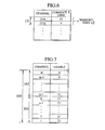
- the comparison unit 13 compares the receiving level with a prescribed threshold for each of the frequencies 121a and 121b of the downlink frequencies supplied to the memory unit 12, and supplies the comparison result to the judgement unit 14. According to the supplied comparison result for each of the frequencies 121a and 121b. the judgement unit 14 judges that the frequency is currently used when the receiving level is greater than the threshold, or that the frequency is not currently used when the receiving level is less than or equal to the threshold. The judgement unit 14 maintains the judgement result for each of the frequencies 121a and 121b in a form of a table as shown in Fig. 6, for example.
- the control. unit 16 judges whether either one of the frequencies 121a and 121b corresponding to the potentially interferred frequency band 111 is currently used or not, at the step S2. When all the frequencies 121a and 121b are not currently used, no interference will be caused to the radio communication system 2 even when a communication channel in the interferring frequency band 102 described above is used as a communication channel by the radio communication system 1. For this reason, the control unit 16 releases the limitation of the communication channel by the radio channel set up unit 15a at the step S3, and waits for the execution of the step S1. In this way, it becomes possible to allocate a communication channel in the interferring frequency band 102, in the communication channel allocation by the radio channel set up unit 15a.
- control unit 16 executes the processing of the step S4 and subsequent steps in order to limit the set up of the communication channel by the radio channel set up unit 15a.
- This limitation of the communication channel set up by the radio channel set up unit 15a is carried out by using a table shown in Fig. 7, for example.
- This table stores in correspondence all the communication channels that can possibly be used in the radio communication system 1 and information indicating whether the use of each of these communication channels is limited or not.
- the control unit 16 detects whether the communication channel in the interferring frequency band 102 is currently used or not.
- the control unit 16 commands the radio channel set up unit 15a to switch that currently used communication channel to the frequency band 101 other than the interferring frequency band 102 in the frequency band 100 that can be used by the radio communication system 1, at the step S5.
- the control unit 16 limits the use of the communication channel in the interferring frequency band 102 by updating the table shown in Fig. 7 described above. Thereafter, the control unit 16 waits for the execution of the step S1 described above.
- step S5 is not executed and the processing proceeds to the step S6, where the use of the communication channel in the interferring frequency band 102 is limited. In this way, only the communication channel in the frequency band 1.01 other than the interferring frequency band 102 will be allocated, in the communication channel allocation by the radio channel set up unit 15a.
- the radio communication system 2 whether or not the radio communication system 2 is using a frequency with respect to which interferences can possibly be caused by the spurious components when the communication channel in the interferring frequency band 102 is used, and when the radio communication system 2 is using that frequency, the communication channel outside the interferring frequency band 102 is allocated as the communication channel to be used by the radio communication system 1, such that it is possible to contribute to the reduction of the interferences caused to the radio communication system 2 due to the spurious components by the radio communication system 1.
- the base station 10 when the base station 10 is configured to carry out communications by using a plurality of communication channels simultaneously, there can be cases where the intermodulation distortion components due to the non-linearity of the RF amplifier 15d or the like are generated as the spurious components.
- these spurious components due to the intermodulation distortion components can be expressed in general as a•fc 1 + b•fc 2 , where a and b are arbitrary non-zero integers.
- the third intermodulation distortion components 2•fc 1 -fc 2 and 2•fc 2 -fc 1 shown in Fig.
- spurious components 4 are generated as relatively high level spurious components in frequency bands close to the carrier frequencies fc 1 and fc 2 to cause some problems. Also, the frequencies of these spurious components due to the intermodulation distortion components can vary according to a combination of the communication channels to be used by the base station 10.
- the frequencies of such spurious components can be predicted in advance according to a combination of frequencies of the communication channels to be used by the base station 10. For this reason, in this radio communication system 1, combinations of the communication channels that can cause interferences to the potentially interferred frequency band 111 due to the spurious components are obtained in advance, and it is made possible to control the combination of the communication channels to be used by the base station 10 according to whether a frequency in the potentially interferred frequency band 111 is used by the radio communication system 2 or not.
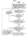
- the control unit 16 obtains the combinations of communication channels that can cause interferences to the potentially interferred frequency band 111 due to the spurious components in advance, by the procedure shown in Fig. 8, for example. These combinations are stored by the control unit 16, for example. In addition, at this point, the frequencies of the spurious components that can be generated by each combination are obtained and stored by the control unit 16.
- the step S12 in Fig. 8 is executed at a prescribed interval similarly as the step S1 of Fig. 5 described above.
- the potentially interferred frequency receiving unit 11 detects the receiving levels of the prescribed frequencies 121a and 121b of the downlink frequencies corresponding to the potentially interferred frequency band 111, and supplies them into the memory unit 12.
- the comparison unit 13 compares the receiving level with a prescribed threshold for each of the frequencies 121a and 121b of the downlink frequencies supplied to the memory unit 12, and supplies the comparison result to the judgement unit 14. According to the supplied comparison result for each of the frequencies 121a and 121b, the judgement unit 14 judges that the frequency is currently used when the receiving level is greater than the threshold, or that the frequency is not currently used when the receiving level is less than or equal to the threshold.
- the control unit 16 judges whether either one of the frequencies 121a and 121b corresponding to the potentially interferred frequency band 111 is currently used or not, at the step S13.
- the control unit 16 releases the limitation on a combination of the communication channels by the radio channel set up unit 15a at the step S14, and waits for the execution of the step S12. In this way, it becomes possible to allocate every combination of communication channels in the communication channel allocation by the radio channel set up unit 15a.
- the control unit 16 judges whether one of the frequencies 121a and 121b that is currently used is a downlink frequency corresponding to a frequency (uplink frequency) corresponding to a combination of the communication channels obtained by the step S11 described above or not.
- step S11 If one of the frequencies 121a and 121b that is currently used is not a downlink frequency corresponding to a frequency (uplink frequency) corresponding to a combination of the communication channels obtained by the step S11, the processing proceeds to the step S14 in order not to cause the interferences to the radio communication system 2 by the spurious components from the base station 10, the limitation on the combination of the communication channels is released, and the execution of the step S12 is waited.
- one of the frequencies 121a and 121b that is currently used is a downlink frequency corresponding to a frequency (uplink frequency) corresponding to one of the combinations of the communication channels obtained by the step S11, there is a possibility for causing the interferences to the potentially interferred frequency band 111 if that combination of the communication channels is used.
- control unit 16 executes the processing of the step S16 and subsequent steps in order to limit that combination of the communication channels by the radio channel set up unit 15a. At this point, the control unit 16 first detects whether that combination of the communication channels is currently used or not.
- control unit 16 commands the radio channel set up unit 15a to switch that currently used combination of the communication channels to another available combination, at the step S17.
- control unit 16 limits an available combination of the communication channels at the step S18. Thereafter, the control unit 16 waits for the execution of the step S12 described above.
- step S17 is not executed and the processing proceeds to the step S18, where the combination of the communication channels is limited. In this way, only the combination of the communication channels that does not cause the interferences to the potentially interferred frequency band 111 will be allocated as a combination of the communication channels by the radio channel set up unit 15a.
- the combinations of the communication channels that can cause the interferences to the potentially interferred frequency band 111 by the spurious components are obtained in advance, and a combination of communication channels to be used by the base station 10 is controlled according to whether or not a frequency in the potentially interferred frequency band 111 is used by the radio communication system 2. In this way, it is possible to contribute to the reduction of the interferences caused to the radio communication system 2 due to the spurious components by the radio communication system 1.
- the present invention has been described from a viewpoint of reducing the interferences caused to the radio communication system 2 by the radio communication 1, but it is also possible to apply the present invention to reduce the interferences caused to the radio communication system 1 by the radio communication system 2.
- the application target of the present invention is nut limited to the above described embodiment, and the present invention is applicable to any case of preventing the interferences between the radio communication systems that use close frequencies.
- the above embodiment is directed to the case where the radio communication system 2 uses the FDD (Frequency Division Duplex) scheme in which the uplink frequency and the downlink frequency are different, but it is also possible to apply the present invention to the case of using the TDD (Time Division Duplex) scheme in which the uplink and the downlink are multiplexed on a time axis.
- FDD Frequency Division Duplex
- TDD Time Division Duplex
- the communication channels are further divided in time by the time-slots in the potentially interferred frequency band, so that it is possible to avoid the interferences by controlling the allocation of the communication channels by predicting the presence or absence of the interferences in units of the time-slots.
- the present invention is also applicable not only for the avoidance of interferences between different radio communication systems but also to the avoidance of interferences between the same radio communication systems such as between the PHSs or the IMT-2000 systems, for example.
- the utilization state of a prescribed frequency in the first frequency band that causes interferences to the first communication system when the communication channel of a particular frequency in the second frequency band is used at the second communication system is detected, and if the prescribed frequency in the first frequency band is currently used, the communication channel other than that of the particular frequency is allocated to the second communication system.
- the detection unit detects the utilization state of a prescribed frequency in the first frequency band that causes interferences to the first communication system when the communication channel of a particular frequency in the second frequency band is used at the second communication system, and if the prescribed frequency in the first frequency band is currently used, the communication channel other than that of the particular frequency is allocated to the second communication system.
Landscapes
- Engineering & Computer Science (AREA)
- Computer Networks & Wireless Communication (AREA)
- Signal Processing (AREA)
- Mobile Radio Communication Systems (AREA)
- Noise Elimination (AREA)
Abstract
Description
Claims (8)
- A communication channel set up method for setting up a communication channel to be used by a second radio communication system that can use a second frequency band close to a first frequency band that can be used by a first radio communication system, comprising:detecting a utilization state of a prescribed frequency in the first frequency band that can cause interferences to the first radio communication system when a communication channel of a particular frequency in the second frequency band is used by the second radio communication system; andallocating a communication channel other than that of the particular frequency to the second radio communication system when the prescribed frequency in the first frequency band is currently used by the first radio communication system.
- The communication channel set up method of claim 1, wherein the first radio communication system uses an uplink frequency in the first frequency band and a downlink frequency corresponding to the uplink frequency, and
the detecting step detects the utilization state of the prescribed frequency in the first frequency band according to a utilization state of the downlink frequency corresponding to the uplink frequency or the uplink frequency corresponding to the downlink frequency when the prescribed frequency in the first frequency band is the uplink frequency or the downlink frequency, respectively. - The communication channel set up method of claim 1, wherein the detecting step includes:detecting a signal strength of the prescribed frequency in the first frequency band; andjudging that signals of the prescribed frequency are currently used when a detected signal strength is greater than a prescribed threshold.
- The communication channel set up method of claim 1, wherein the detecting step includes:obtaining the prescribed frequency in the first frequency band by receiving signals from the first radio communication system at the second radio communication system.
- A communication control device for controlling a communication channel to be used by a second radio communication system that can use a second frequency band close to a first frequency band that can be used by a first radio communication system, comprising;a detection unit configured to detect a utilization state of a prescribed frequency in the first frequency band that can cause interferences to the first radio communication system when a communication channel of a particular frequency in the second frequency band is used by the second radio communication system; andan allocation unit configured to allocate a communication channel other than that of the particular frequency to the second radio communication system when the prescribed frequency in the first frequency band is currently used by the first radio communication system.
- The communication control device of claim 5, wherein the first radio communication system uses an uplink frequency in the first frequency band and a downlink frequency corresponding to the uplink frequency, and
the detection unit detects the utilization state of the prescribed frequency in the first frequency band according to a utilization state of the downlink frequency corresponding to the uplink frequency or the uplink frequency corresponding to the downlink frequency when the prescribed frequency in the first frequency band is the uplink frequency or the downlink frequency, respectively. - The communication control device of claim 5, wherein the detection unit is configured to detect a signal strength of the prescribed frequency In the first frequency band, and Judge that signals of the prescribed frequency are currently used when a detected signal strength is greater than a prescribed threshold.
- The communication control device of claim 5, wherein the detection unit is configured to obtain the prescribed frequency in the first frequency band by receiving signals from the first radio communication system at the second radio communication system.
Applications Claiming Priority (2)
| Application Number | Priority Date | Filing Date | Title |
|---|---|---|---|
| JP2001157797 | 2001-05-25 | ||
| JP2001157797A JP4014823B2 (en) | 2001-05-25 | 2001-05-25 | Communication channel setting method and communication control apparatus |
Publications (3)
| Publication Number | Publication Date |
|---|---|
| EP1261225A2 true EP1261225A2 (en) | 2002-11-27 |
| EP1261225A3 EP1261225A3 (en) | 2003-09-03 |
| EP1261225B1 EP1261225B1 (en) | 2005-01-26 |
Family
ID=19001607
Family Applications (1)
| Application Number | Title | Priority Date | Filing Date |
|---|---|---|---|
| EP02011537A Expired - Lifetime EP1261225B1 (en) | 2001-05-25 | 2002-05-23 | Communication channel set up method and communication control device for reducing interference between radio communication systems |
Country Status (5)
| Country | Link |
|---|---|
| US (1) | US7181166B2 (en) |
| EP (1) | EP1261225B1 (en) |
| JP (1) | JP4014823B2 (en) |
| CN (1) | CN100433589C (en) |
| DE (1) | DE60202714T2 (en) |
Cited By (7)
| Publication number | Priority date | Publication date | Assignee | Title |
|---|---|---|---|---|
| WO2005086516A1 (en) | 2004-03-05 | 2005-09-15 | Ntt Docomo, Inc. | Frequency channel assigning system, base station, control station, inter-system common control apparatus, frequency channel assigning method and control method |
| WO2005099174A1 (en) * | 2004-04-08 | 2005-10-20 | Koninklijke Philips Electronics N.V. | Dynamic frequency selection for a wireless system |
| US7720029B2 (en) | 2003-03-07 | 2010-05-18 | Nokia Corporation | Channel selection in wireless telecommunication system |
| CN1905731B (en) * | 2005-07-27 | 2010-09-29 | 鸿富锦精密工业(深圳)有限公司 | Access point and wireless channel selecting method thereof |
| EP2139275A3 (en) * | 2008-06-25 | 2014-01-15 | Honeywell International Inc. | System and method to deterministically and dynamically prevent interference to the operation of safety-of-life radio equipment |
| US20170273085A1 (en) * | 2014-08-25 | 2017-09-21 | Telefonaktiebolaget Lm Ericsson (Publ) | Subcarrier allocation device and method for allocating n channels to carrier frequencies |
| US10375711B2 (en) | 2013-11-12 | 2019-08-06 | Qualcomm Incorporated | Methods for LTE channel selection in unlicensed bands |
Families Citing this family (21)
| Publication number | Priority date | Publication date | Assignee | Title |
|---|---|---|---|---|
| DE10339898B4 (en) * | 2003-08-29 | 2007-03-22 | Siemens Ag | Method for operating a base station of a mobile radio system, signaling unit, control unit, mobile station and computer program |
| JP2005086408A (en) * | 2003-09-08 | 2005-03-31 | Sony Corp | Wireless communication system, wireless communication apparatus, wireless communication method, and computer program |
| US7848741B2 (en) | 2003-12-30 | 2010-12-07 | Kivekaes Kalle | Method and system for interference detection |
| US7835701B2 (en) * | 2004-03-29 | 2010-11-16 | Edgewater Computer Systems, Inc. | Detecting and eliminating spurious energy in communications systems via multi-channel processing |
| CN100377505C (en) * | 2004-04-01 | 2008-03-26 | 深圳市三比特技术有限公司 | Compatible method of direct expanded digital radio communication and radio local net |
| US7643811B2 (en) * | 2004-05-26 | 2010-01-05 | Nokia Corporation | Method and system for interference detection |
| JP2006345243A (en) * | 2005-06-09 | 2006-12-21 | Matsushita Electric Ind Co Ltd | Base station apparatus, communication terminal apparatus and transmission method |
| JP4763374B2 (en) | 2005-07-25 | 2011-08-31 | パナソニック株式会社 | Output control device |
| TW200721861A (en) * | 2005-09-09 | 2007-06-01 | Nokia Corp | Use of measurement pilot for radio measurement in a wireless network |
| JP4917425B2 (en) * | 2006-12-28 | 2012-04-18 | 株式会社ユニバーサルエンターテインメント | Wireless IC tag reading device, its control device, and wireless IC tag reading system |
| KR101110602B1 (en) * | 2007-02-08 | 2012-03-08 | 가부시키가이샤 엔티티 도코모 | Radio communication system, least significant station, and intermediate station |
| JP2008205743A (en) * | 2007-02-19 | 2008-09-04 | Ntt Docomo Inc | Control device |
| US20080207259A1 (en) * | 2007-02-26 | 2008-08-28 | Broadcom Corporation, A California Corporation | Dual RF transceiver system with interference cancellation and methods for use therewith |
| JP2009033628A (en) * | 2007-07-30 | 2009-02-12 | Yokosuka Telecom Research Park:Kk | Wireless system and communication method |
| JP5111536B2 (en) * | 2009-04-27 | 2013-01-09 | 株式会社エヌ・ティ・ティ・ドコモ | User apparatus, base station apparatus, and communication control method |
| JP5697092B2 (en) * | 2011-04-04 | 2015-04-08 | 独立行政法人情報通信研究機構 | Reception discrimination system |
| JP6162992B2 (en) * | 2013-03-27 | 2017-07-12 | 京セラ株式会社 | COMMUNICATION DEVICE, COMMUNICATION METHOD, AND COMMUNICATION SYSTEM |
| CN103795480B (en) * | 2014-01-27 | 2016-04-27 | 中国电子科技集团公司第十研究所 | Beam system multichannel networking testing apparatus |
| JP6439519B2 (en) * | 2015-03-16 | 2018-12-19 | 沖電気工業株式会社 | Wireless communication apparatus, wireless communication method, and program |
| CN106413101B (en) * | 2016-11-17 | 2019-12-03 | 维沃移动通信有限公司 | Method for avoiding self-interference channel and mobile terminal |
| KR102668217B1 (en) * | 2019-03-11 | 2024-05-23 | 삼성전자주식회사 | Method for controlling frequency band for communication and electronic device thereof |
Family Cites Families (7)
| Publication number | Priority date | Publication date | Assignee | Title |
|---|---|---|---|---|
| US5978362A (en) * | 1996-02-06 | 1999-11-02 | Airtouch Communications, Inc. | Method and apparatus for eliminating intermodulation interference in cellular telephone systems |
| US5890056A (en) * | 1996-07-09 | 1999-03-30 | Lucent Technologies, Inc. | Channel usage monitoring arrangement for base station |
| US6101176A (en) * | 1996-07-24 | 2000-08-08 | Nokia Mobile Phones | Method and apparatus for operating an indoor CDMA telecommunications system |
| JP3308868B2 (en) | 1997-08-12 | 2002-07-29 | 株式会社エヌ・ティ・ティ・ドコモ | Reconnection channel switching method for anti-interference |
| JP3109504B2 (en) | 1998-03-27 | 2000-11-20 | 日本電気株式会社 | Cellular system, method for avoiding adjacent frequency interference in cellular system, and mobile station |
| JP3334658B2 (en) | 1999-01-07 | 2002-10-15 | 三菱マテリアル株式会社 | Wireless communication processing device and recording medium thereof |
| SE521227C2 (en) * | 1999-02-22 | 2003-10-14 | Ericsson Telefon Ab L M | Mobile radio system and a method for channel allocation in a mobile radio system |
-
2001
- 2001-05-25 JP JP2001157797A patent/JP4014823B2/en not_active Expired - Fee Related
-
2002
- 2002-05-22 CN CNB021204349A patent/CN100433589C/en not_active Expired - Fee Related
- 2002-05-23 DE DE60202714T patent/DE60202714T2/en not_active Expired - Lifetime
- 2002-05-23 EP EP02011537A patent/EP1261225B1/en not_active Expired - Lifetime
- 2002-05-24 US US10/153,898 patent/US7181166B2/en not_active Expired - Fee Related
Cited By (9)
| Publication number | Priority date | Publication date | Assignee | Title |
|---|---|---|---|---|
| US7720029B2 (en) | 2003-03-07 | 2010-05-18 | Nokia Corporation | Channel selection in wireless telecommunication system |
| WO2005086516A1 (en) | 2004-03-05 | 2005-09-15 | Ntt Docomo, Inc. | Frequency channel assigning system, base station, control station, inter-system common control apparatus, frequency channel assigning method and control method |
| EP1732338A4 (en) * | 2004-03-05 | 2011-06-29 | Ntt Docomo Inc | FREQUENCY CHANNEL ASSIGNMENT SYSTEM, BASE STATION, CONTROL STATION, INTER-SYSTEM COMMON CONTROL APPARATUS, FREQUENCY CHANNEL ASSIGNMENT METHOD, AND CONTROL METHOD |
| US8204004B2 (en) | 2004-03-05 | 2012-06-19 | Ntt Docomo, Inc. | Frequency channel assignment system, base station, control station, inter-system common control apparatus, frequency channel assignment method, and control method |
| WO2005099174A1 (en) * | 2004-04-08 | 2005-10-20 | Koninklijke Philips Electronics N.V. | Dynamic frequency selection for a wireless system |
| CN1905731B (en) * | 2005-07-27 | 2010-09-29 | 鸿富锦精密工业(深圳)有限公司 | Access point and wireless channel selecting method thereof |
| EP2139275A3 (en) * | 2008-06-25 | 2014-01-15 | Honeywell International Inc. | System and method to deterministically and dynamically prevent interference to the operation of safety-of-life radio equipment |
| US10375711B2 (en) | 2013-11-12 | 2019-08-06 | Qualcomm Incorporated | Methods for LTE channel selection in unlicensed bands |
| US20170273085A1 (en) * | 2014-08-25 | 2017-09-21 | Telefonaktiebolaget Lm Ericsson (Publ) | Subcarrier allocation device and method for allocating n channels to carrier frequencies |
Also Published As
| Publication number | Publication date |
|---|---|
| JP4014823B2 (en) | 2007-11-28 |
| CN100433589C (en) | 2008-11-12 |
| EP1261225A3 (en) | 2003-09-03 |
| US20020177414A1 (en) | 2002-11-28 |
| CN1388663A (en) | 2003-01-01 |
| DE60202714D1 (en) | 2005-03-03 |
| DE60202714T2 (en) | 2005-12-22 |
| US7181166B2 (en) | 2007-02-20 |
| EP1261225B1 (en) | 2005-01-26 |
| JP2002354531A (en) | 2002-12-06 |
Similar Documents
| Publication | Publication Date | Title |
|---|---|---|
| US7181166B2 (en) | Communication channel set up method and communication control device for reducing interferences between radio communication systems | |
| US6643522B1 (en) | Method and apparatus providing simultaneous dual mode operations for radios in the shared spectrum | |
| US7155233B2 (en) | Radio communication system for reducing interferences with respect to other communication system using close frequency band | |
| EP1128573B1 (en) | Method for avoiding adjacent carrier frequency interference | |
| EP0953259B1 (en) | A connection establishment method, a subscriber terminal unit and a radio system | |
| EP1308056B1 (en) | System and method for reuse of communications spectrum for fixed and mobile applications with efficent method to mitigate interference | |
| US8155032B2 (en) | Adaptive scheduling for half-duplex wireless terminals | |
| EP2289278B1 (en) | Adaptive coexistence between different wireless communication systems | |
| CA2063901C (en) | Cellular data overlay system | |
| US7826850B2 (en) | Frequency band allocation device and method | |
| US5761622A (en) | Method and apparatus for controlling operation of a portable or mobile battery-operated radios | |
| US20060160551A1 (en) | Frequency band allocation device and method | |
| JP2001501793A (en) | Method and apparatus for mitigating intermodulation effects in a multiple signal transmission system | |
| US11910261B2 (en) | Adaptive channel orchestration | |
| KR20020026277A (en) | Base station apparatus and handover control method | |
| US5101503A (en) | Method of connecting channels of decentralized radio systems | |
| JP3107048B2 (en) | CDMA communication system and frequency allocation method in CDMA communication system | |
| US7039414B1 (en) | Apparatus and method for allowing communication systems to coexist | |
| EP4395426A1 (en) | Systems, methods, and devices for power management in channel hopping scheme | |
| US10863518B2 (en) | Method for handling interference in Bluetooth device having other wireless technology | |
| US20070087700A1 (en) | Radio base station, communications program and communications method | |
| JP3806007B2 (en) | COMMUNICATION CHANNEL ALLOCATION METHOD, COMMUNICATION CONTROL DEVICE, AND RADIO COMMUNICATION SYSTEM | |
| JP2850619B2 (en) | Transmission power control method for mobile communication system | |
| KR100266540B1 (en) | Reduce method of synchronization time with pilot channel in fhma(frequency hopping/code division multiple-access) system | |
| JP2005012366A (en) | Wireless communication system and wireless communication method |
Legal Events
| Date | Code | Title | Description |
|---|---|---|---|
| PUAI | Public reference made under article 153(3) epc to a published international application that has entered the european phase |
Free format text: ORIGINAL CODE: 0009012 |
|
| 17P | Request for examination filed |
Effective date: 20020523 |
|
| AK | Designated contracting states |
Kind code of ref document: A2 Designated state(s): AT BE CH CY DE DK ES FI FR GB GR IE IT LI LU MC NL PT SE TR |
|
| AX | Request for extension of the european patent |
Free format text: AL;LT;LV;MK;RO;SI |
|
| PUAL | Search report despatched |
Free format text: ORIGINAL CODE: 0009013 |
|
| AK | Designated contracting states |
Kind code of ref document: A3 Designated state(s): AT BE CH CY DE DK ES FI FR GB GR IE IT LI LU MC NL PT SE TR |
|
| AX | Request for extension of the european patent |
Extension state: AL LT LV MK RO SI |
|
| 17Q | First examination report despatched |
Effective date: 20031217 |
|
| AKX | Designation fees paid |
Designated state(s): DE GB |
|
| GRAP | Despatch of communication of intention to grant a patent |
Free format text: ORIGINAL CODE: EPIDOSNIGR1 |
|
| GRAS | Grant fee paid |
Free format text: ORIGINAL CODE: EPIDOSNIGR3 |
|
| GRAA | (expected) grant |
Free format text: ORIGINAL CODE: 0009210 |
|
| AK | Designated contracting states |
Kind code of ref document: B1 Designated state(s): DE GB |
|
| REG | Reference to a national code |
Ref country code: GB Ref legal event code: FG4D |
|
| REG | Reference to a national code |
Ref country code: IE Ref legal event code: FG4D |
|
| REF | Corresponds to: |
Ref document number: 60202714 Country of ref document: DE Date of ref document: 20050303 Kind code of ref document: P |
|
| PLBE | No opposition filed within time limit |
Free format text: ORIGINAL CODE: 0009261 |
|
| STAA | Information on the status of an ep patent application or granted ep patent |
Free format text: STATUS: NO OPPOSITION FILED WITHIN TIME LIMIT |
|
| 26N | No opposition filed |
Effective date: 20051027 |
|
| PGFP | Annual fee paid to national office [announced via postgrant information from national office to epo] |
Ref country code: DE Payment date: 20120516 Year of fee payment: 11 |
|
| PGFP | Annual fee paid to national office [announced via postgrant information from national office to epo] |
Ref country code: GB Payment date: 20120523 Year of fee payment: 11 |
|
| REG | Reference to a national code |
Ref country code: DE Ref legal event code: R119 Ref document number: 60202714 Country of ref document: DE |
|
| GBPC | Gb: european patent ceased through non-payment of renewal fee |
Effective date: 20130523 |
|
| PG25 | Lapsed in a contracting state [announced via postgrant information from national office to epo] |
Ref country code: DE Free format text: LAPSE BECAUSE OF NON-PAYMENT OF DUE FEES Effective date: 20131203 |
|
| PG25 | Lapsed in a contracting state [announced via postgrant information from national office to epo] |
Ref country code: GB Free format text: LAPSE BECAUSE OF NON-PAYMENT OF DUE FEES Effective date: 20130523 |
|
| REG | Reference to a national code |
Ref country code: DE Ref legal event code: R079 Ref document number: 60202714 Country of ref document: DE Free format text: PREVIOUS MAIN CLASS: H04Q0007360000 Ipc: H04W0016000000 |
|
| REG | Reference to a national code |
Ref country code: DE Ref legal event code: R119 Ref document number: 60202714 Country of ref document: DE Effective date: 20131203 Ref country code: DE Ref legal event code: R079 Ref document number: 60202714 Country of ref document: DE Free format text: PREVIOUS MAIN CLASS: H04Q0007360000 Ipc: H04W0016000000 Effective date: 20140523 |