EP1261145B1 - Downlink transmission power control - Google Patents
Downlink transmission power control Download PDFInfo
- Publication number
- EP1261145B1 EP1261145B1 EP01304652A EP01304652A EP1261145B1 EP 1261145 B1 EP1261145 B1 EP 1261145B1 EP 01304652 A EP01304652 A EP 01304652A EP 01304652 A EP01304652 A EP 01304652A EP 1261145 B1 EP1261145 B1 EP 1261145B1
- Authority
- EP
- European Patent Office
- Prior art keywords
- unit
- node
- value
- power
- telecommunications network
- Prior art date
- Legal status (The legal status is an assumption and is not a legal conclusion. Google has not performed a legal analysis and makes no representation as to the accuracy of the status listed.)
- Expired - Lifetime
Links
Images
Classifications
-
- H—ELECTRICITY
- H04—ELECTRIC COMMUNICATION TECHNIQUE
- H04W—WIRELESS COMMUNICATION NETWORKS
- H04W52/00—Power management, e.g. TPC [Transmission Power Control], power saving or power classes
- H04W52/04—TPC
- H04W52/06—TPC algorithms
- H04W52/14—Separate analysis of uplink or downlink
-
- H—ELECTRICITY
- H04—ELECTRIC COMMUNICATION TECHNIQUE
- H04W—WIRELESS COMMUNICATION NETWORKS
- H04W52/00—Power management, e.g. TPC [Transmission Power Control], power saving or power classes
- H04W52/04—TPC
- H04W52/18—TPC being performed according to specific parameters
- H04W52/20—TPC being performed according to specific parameters using error rate
-
- H—ELECTRICITY
- H04—ELECTRIC COMMUNICATION TECHNIQUE
- H04W—WIRELESS COMMUNICATION NETWORKS
- H04W88/00—Devices specially adapted for wireless communication networks, e.g. terminals, base stations or access point devices
- H04W88/12—Access point controller devices
-
- H—ELECTRICITY
- H04—ELECTRIC COMMUNICATION TECHNIQUE
- H04W—WIRELESS COMMUNICATION NETWORKS
- H04W52/00—Power management, e.g. TPC [Transmission Power Control], power saving or power classes
- H04W52/04—TPC
- H04W52/06—TPC algorithms
- H04W52/12—Outer and inner loops
-
- H—ELECTRICITY
- H04—ELECTRIC COMMUNICATION TECHNIQUE
- H04W—WIRELESS COMMUNICATION NETWORKS
- H04W52/00—Power management, e.g. TPC [Transmission Power Control], power saving or power classes
- H04W52/04—TPC
- H04W52/18—TPC being performed according to specific parameters
- H04W52/26—TPC being performed according to specific parameters using transmission rate or quality of service QoS [Quality of Service]
Definitions
- the present invention relates to a telecommunications network, a method of adjusting maximum transmission power, a base station, and a radio network controller.
- UMTS Universal Mobile Telephone Service
- OPC outer loop power control
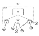
- the downlink transmission power control block in the UMTS Terrestrial Radio Access Network (UTRAN), specifically in a Radio Network Controller (RNC) of the UTRAN.
- RNC Radio Network Controller
- SIR signal to interference radios
- UE subscriber units
- there is relatively more signalling required across the radio link (Uu interface) between base station (Node B) and subscriber units (UE) also more processing must be done by the radio network controller (RNC) than otherwise.
- a known alternative is to locate the control block downlink transmission power in the respective subscriber units (UE's) themselves.
- the UE compares the measured SIR (SIR-estimate) against the SIR-target. If the SIR-estimate is less than the SIR-target, the UE sends a transmission power control command (TPC) to require the base station (UTRAN) to increase its transmission power.
- TPC transmission power control command
- subscriber units (UE) have total control over the downlink transmit power from the UTRAN.
- EP-A-1 081 977 and EP-A-1081 978 describe arrangements in which a slow power control loop uses error measurements to calculate a SIR target and a fast power control loop uses a comparison of measured SIR with target SIR to adjust power transmission.
- WO 02/39609 published after the filing date of the present application, describes an arrangement in which the power level of a forward link is adjusted based on the number of frame errors in transmissions to a subscriber unit.
- the present invention provides a telecommunications network comprising a first unit and a second unit, the second unit comprising means operative to determine a value representative of the accuracy with which data is received from the first unit and to transmit said value to the first unit, the first unit being operative to adjust the maximum power with which the first unit sends data to the second unit dependent upon said value.
- the first unit is a base station and the second unit is a subscriber unit, both operative to send data by radio, the maximum power which is adjusted being the maximum downlink power.
- the present invention in its preferred embodiments solves the problem of subscriber units setting unnecessarily or unreasonably strict SIR targets resulting in unnecessarily or unreasonably high base station transmission powers and consequential interference problems.
- the maximum downlink (DL) transmission power is not only set in initial Radio Link Setup stage, but is adjusted during the whole life cycle of a call to limit the base station UTRAN transmission power required by subscriber units UE.
- the maximum downlink DL power is repeatedly adjusted during the whole life cycle of a call to limit the UTRAN transmission power required to transmit to the subscriber unit UE.
- an information element (value) representing maximum downlink power for the UTRAN is used to dynamically adjust (i.e. adjust 'on the fly' i.e. during the call) downlink transmission power to a particular subscriber unit.
- the UTRAN transmission power is a finite resource so a 'selfish UE' if allowed to be selfish would request more power at the expense of other UE's.
- the present invention also provides a method of adjusting maximum power in a call between a first unit and a second unit in a telecommunications network, comprising the steps of:
- the present invention also provides a base station comprising means operative to receive from a subscriber unit a value representative of the accuracy with which data sent downlink from the base station was received, the base station further comprising means operative to adjust the maximum downlink power for further downlink data transmissions dependent upon said value.
- the present invention also provides a radio network controller (RNC) comprising comparator means operative to process a value representative of accuracy with which data was received by a subscriber unit by comparing said value to at least one threshold, and dependent upon the outcome of the or each comparison generating a control signal for adjusting maximum downlink transmission power of a transmitter/receiver station (Node B).
- RNC radio network controller
- the transmittter/receiver station (Node B), its controlling (serving) radio network controller (SRNC) and any particular subscriber unit (UE) with which a call is to be established operate as follows:
- Steps 7 to 9 occur repeatedly and automatically during the course of the call.
- the maximum downlink power level is adjusted in steps, the size of which are set by the radio network controller (SRNC).
- a step is, for example, at least 0.1dB when used in the range 35dB to 15dB to achieve a fast adjustment.
- a minimum power step size is defined in the UMTS 3 rd Generation Partnership project standard as being 0.1 dB in that power range).
Description
- The present invention relates to a telecommunications network, a method of adjusting maximum transmission power, a base station, and a radio network controller.
- As is known from, for example 3rd Generation Partnership Project Technical Specifications documents TS25.433, TS25.214 and TS25.331, in, for example, a Universal Mobile Telephone Service (UMTS) network there are requirements to control the power of signals sent downlink from base stations (Node B's) to subscriber units (user equipment UE's) so as to minimise interference between signals to subscribers who share common frequency bands.
- There is a requirement for so-called outer loop power control (OLPC) discussed in the above mentioned standards. In essence this relates to the slower rate (or courser) downlink transmission power control i.e. control of maximum downlink transmission power as compared to the inner loop power control relating to faster rate and finer adjustment.
- It is known to locate the downlink transmission power control block in the UMTS Terrestrial Radio Access Network (UTRAN), specifically in a Radio Network Controller (RNC) of the UTRAN. This allows the radio network controller to set the downlink transmission power based on predicting the signal to interference radios (SIR) which should be acceptable for downlink transmissions to various subscriber units (UE). However, there is relatively more signalling required across the radio link (Uu interface) between base station (Node B) and subscriber units (UE) also more processing must be done by the radio network controller (RNC) than otherwise.
- A known alternative is to locate the control block downlink transmission power in the respective subscriber units (UE's) themselves. In known downlink outer loop power control, the UE compares the measured SIR (SIR-estimate) against the SIR-target. If the SIR-estimate is less than the SIR-target, the UE sends a transmission power control command (TPC) to require the base station (UTRAN) to increase its transmission power. In this known approach, subscriber units (UE) have total control over the downlink transmit power from the UTRAN. Although advantageously allowing effects which degrade the downlink signal to be taken into account when determining the SIR-target in the subscriber unit, in particular in its RAKE receiver, and requiring relatively less signalling traffic between base stations (Node B) and subscriber unit (UE), there is at least one significant disadvantage to this known approach.
- It is that manufacturers of subscriber units may set stricter than necessary SIR-targets resulting in higher than strictly necessary downlink transmission power levels to be used. The result would be significant interference which would be unpredictable and could be high.
-
EP-A-1 081 977 andEP-A-1081 978 describe arrangements in which a slow power control loop uses error measurements to calculate a SIR target and a fast power control loop uses a comparison of measured SIR with target SIR to adjust power transmission.WO 02/39609 - The present invention provides a telecommunications network comprising a first unit and a second unit, the second unit comprising means operative to determine a value representative of the accuracy with which data is received from the first unit and to transmit said value to the first unit, the first unit being operative to adjust the maximum power with which the first unit sends data to the second unit dependent upon said value.
- Preferably the first unit is a base station and the second unit is a subscriber unit, both operative to send data by radio, the maximum power which is adjusted being the maximum downlink power.
- The present invention in its preferred embodiments solves the problem of subscriber units setting unnecessarily or unreasonably strict SIR targets resulting in unnecessarily or unreasonably high base station transmission powers and consequential interference problems.
- Preferably the maximum downlink (DL) transmission power is not only set in initial Radio Link Setup stage, but is adjusted during the whole life cycle of a call to limit the base station UTRAN transmission power required by subscriber units UE.
- Preferably the maximum downlink DL power is repeatedly adjusted during the whole life cycle of a call to limit the UTRAN transmission power required to transmit to the subscriber unit UE.
- Preferably an information element (value) representing maximum downlink power for the UTRAN is used to dynamically adjust (i.e. adjust 'on the fly' i.e. during the call) downlink transmission power to a particular subscriber unit. This advantageously prevents a 'selfish UE' from requiring more than necessary transmission power by setting an unreasonable SIR-target irequiring higher than necessary downlink power in order to be satisfied. The UTRAN transmission power is a finite resource so a 'selfish UE' if allowed to be selfish would request more power at the expense of other UE's.
- The present invention also provides a method of adjusting maximum power in a call between a first unit and a second unit in a telecommunications network, comprising the steps of:
- the second unit determining a value representative of the accuracy with which data is received from the first unit,
- the second unit transmitting said value to the first unit,
- the first unit adjusting the maximum power with which the first unit sends data to the second unit dependent upon said value.
- The present invention also provides a base station comprising means operative to receive from a subscriber unit a value representative of the accuracy with which data sent downlink from the base station was received, the base station further comprising means operative to adjust the maximum downlink power for further downlink data transmissions dependent upon said value.
- The present invention also provides a radio network controller (RNC) comprising comparator means operative to process a value representative of accuracy with which data was received by a subscriber unit by comparing said value to at least one threshold, and dependent upon the outcome of the or each comparison generating a control signal for adjusting maximum downlink transmission power of a transmitter/receiver station (Node B).
- A preferred embodiment of the present invention will now be described, by way of example, and with reference to the Figures, in which:
- Figure 1 is a diagram illustrating the UMTS network,
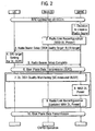
- Figure 2 is a diagram illustrating the sequence of communication steps (denoted 1 to 10) in establishing a call and controlling downlink transmission power during the call, and
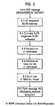
- Figure 3 illustrates in more detail operation of the block in the (serving) radio network controller (SRN) controlling maximum downlink power, in other words it illustrates in
more detail step 8 as shown in Figure 2. - As shown in Figure 2, the transmittter/receiver station (Node B), its controlling (serving) radio network controller (SRNC) and any particular subscriber unit (UE) with which a call is to be established operate as follows:
- 1. A radio resource control (RRC) connection having been set up on a dedicated control channel (DCCH), in other words, a signalling channel, a decision is made to create a radio bearer, i.e. set up a call.
- 2. The SRNC sends the value of the maximum downlink transmission power allowed for that call to the Node B. The allowed power value depends on the type of service (data, voice, video), and the type of subscriber unit so is service-and UE-specific.
- 3. As part of the radio bearer set up, a downlink reception quality target, namely a block error rate (BLER) target, is sent downlink to the UE on the dedicated channel (DCH) which is the channel dedicated to carry the call.
- 4. Based on the received BLER target (or received BLER targets for different types of service (voice, data,fax etc)) the signal interference ratio (SIR) required by the UE is determined. This depends on the construction of the UE. As required by the UMTS standard there is a BLER target required for each type of service (e.g., voice, fax, data, video) which can be handled.
- 5. The UE indicates via the Node B to the SRNC that call set up is complete.
- 6. User data is now transmitted.
- Whilst user data is being transmitted (shown as step 6 and step 10 in Figure 2),
functions 7 to 9 as shown in Figure 2 are operative as follows: - 7. The UE periodically reports its BLER-estimate for each dedicated channel (DCH).
- 8. The UTRAN decides whether or not the downlink transmission power should be adjusted (e.g.down) by examining the reported BLER-estimate over a reasonable period of time.
- 9. If the UTRAN makes such a decision, the RNC will inform the Node B to adjust its maximum downlink transmission power by sending RADIO LINK RECONFIGURATION REQUEST including information element (IE) 'Maximum DL power' to be used for transmission to the particular subscriber unit.
-
Steps 7 to 9 occur repeatedly and automatically during the course of the call. - The maximum downlink power level is adjusted in steps, the size of which are set by the radio network controller (SRNC). A step is, for example, at least 0.1dB when used in the range 35dB to 15dB to achieve a fast adjustment. (A minimum power step size is defined in the UMTS 3rd Generation Partnership project standard as being 0.1 dB in that power range).
- The
functional stage 8 shown in Figure 2 is shown in more detail in Figure 3,and is as follows: - 8.1 The radio network controller RNC extracts the information element IE 'BLER-estimate' (where BLER is block error rate) from the radio resource control RRC message 'MEASUREMENT REPORT' received from the subscriber unit. The RRC message is periodically reported from the UE to the RNC, reasonably frequently such that the RNC can make a judgement e.g. as to whether the subscriber unit's UE BLER implying that UTRAN transmission power is excessive.
- 8.2 The RNC compares the BLER-target set by the RNC and the BLER-estimate measured by the UE to assist the RNC in making a decision whether downlink power adjustment is required.Each type of call has an associated BLER target so as to ensure acceptable quality of service. Thus, for example, calls of the type carrying voice only payload data have different thresholds to those carrying, e.g. video.
- 8.3 The RNC decides if a '+' or '-' i.e. up or down adjustment is necessary. This is based on the comparison in the previous step 8.2. Note that in some embodiments whether adjustment is needed or not can be quite a complicated question in difficult radio environments. In these scenarios, the controlled adjustment can be used as precaution to prevent downlink transmission power from becoming excessive and/or reducing such power if it too became excessive.
- 8.4 The RNC decides the step (or slope) for the adjustment. The recursive algorithm is given as

where P max (t) is the maximum downlink power level to the subscriber unit UE for time t, P max (t -1) is the maximum downlink power level to the subscriber unit UE for the previous time step (t -1) and s is a + or - sign function decided in section 8.3, and Δ step is power update step for changing maximum downlink transmission power. The value of Δ step is set depending on the following factors: frequency of the RRC message "MEASUREMENT REPORTING", the BLER-estimate (a worse BLER-estimate requires or bigger adjustment step), accuracy of the adjustment, time delay of the adjustment, service type (e.g. voice, data, etc), service data rate, service combination (e.g. multimedia or single service type), and radio environment (multipath fading, and weather). - 8.5 The RNC decides the new value of P max. This is done by calculation as mentioned in 8.4 above. P max is translated to the information element IE representing maximum DL transmission power.
- 8.6 The RNC constructs the message RADIO LINK RECONFIGURATION including the information element IE for max DL transmission power and sends it to the Node B to adjust the Node B maximum downlink transmission power.
Claims (16)
- A telecommunications network comprising a first unit (Node B) and a second unit (UE), the second unit (UE) comprising means operative to determine a value representative of the accuracy with which data is received from the first unit (Node B) and characterised by the second unit (UE) being arranged to transmit said value to the first unit (Node B) and the maximum power with which the first unit (Node B) sends data to the second unit (UE) being arranged to be adjusted dependent upon said value.
- A telecommunications network according to claim 1, in which the first unit is a base station (Node B) and the second unit is a subscriber unit (UE), both operative to send data by radio, the maximum power which is adjusted being the maximum downlink power.
- A telecommunications network according to claim 1 or claim 2, in which the value is a measure of Block Error rate, BLER.
- A telecommunications network according to any preceding claim, in which the maximum power, P max, is adjusted downwards dependent upon whether the value is below a predetermined threshold.
- A telecommunications network according to any preceding claim, in which the maximum power, P max, is adjusted upwards dependent upon whether the value is above a predetermined threshold.
- A telecommunications network according to claim 4 or claim 5, in which the threshold(s) are selected dependent upon the type of payload data carried in the call.
- A telecommunications network according to any preceding claim, in which the maximum power, P max, is adjusted by increasing or decreasing maximum power by a discrete step, Δ step, should adjustment be determined as being required.
- A telecommunications network according to claim 6 in which the maximum downlink power, P max, is adjusted according to the relation:

where t is the current adjustment step in time, t-1 is the last adjustment step in time, s is + or - dependent on whether the maximum power is to be increased or decreased, and Δstep is the step change in maximum power to be applied. - A telecommunications network according to any preceding claim, in which the steps of determining the value, transmitting the value to the first unit (Node B) and adjusting the value are repeated during a call between the first unit (Node B) and second unit (UE).
- A telecommunications network according to any preceding claim which is a UMTS network or other third generation network.
- A telecommunications network according to claim 10 which comprises a radio network controller (RNC) and at least one transmitter/receiver station (Node B) under the control of the controller, the controller being operative to instruct the transmitter/receiver station(s) (Node B) to adjust maximum downlink transmission power dependent on said value(s).
- A telecommunications network according to claim 10 or claim 11, in which the maximum power which is adjusted is the outer loop maximum power.
- A method of adjusting maximum downlink power in a call between a first unit (Node B) and a second unit (UE) in a telecommunications network, comprising the steps of:the second unit (UE) determining a value representative of the accuracy with which data is received from the first unit (Node B), and characterised bythe second unit (UE) transmitting said value to the first unit (Node B),the first unit (Node B)adjusting the maximum power with which the first unit (Node B)sends data to the second unit (UE) dependent upon said value.
- A base station (Node B) characterised by means operative to receive from a subscriber unit (UE) a value representative of the accuracy with which data sent downlink from the base station (Node B) was received, and
the base station (Node B) further comprising means operative to adjust the maximum downlink power for further downlink data transmissions dependent upon said value. - A base station according to claim 14 comprising a radio network controller (RNC) and at least one transmitter/receiver station (Node B) which operates under the control of the radio network controller, the radio network controller being operative to instruct the transmitter/receiver station(s) to adjust maximum downlink transmission power dependent upon said value(s) received.
- A radio network controller (RNC) characterised by comparator means operative to process a value representative of accuracy with which data was received by a subscriber unit (UE) by comparing said value to at least one threshold, and dependent upon the outcome of the or each comparison generating a control signal for adjusting maximum downlink transmission power of a transmitter/receiver station (Node B).
Priority Applications (5)
| Application Number | Priority Date | Filing Date | Title |
|---|---|---|---|
| EP01304652A EP1261145B1 (en) | 2001-05-25 | 2001-05-25 | Downlink transmission power control |
| DE60132564T DE60132564T2 (en) | 2001-05-25 | 2001-05-25 | Transmission power control for the downlink |
| US10/123,381 US20020177462A1 (en) | 2001-05-25 | 2002-04-16 | Adjustment of downlink transmission power in a telecommunications network such as a UMTS or other third generation network |
| KR1020020027599A KR100554866B1 (en) | 2001-05-25 | 2002-05-18 | Adjustment of downlink transmission power in a telecommunications network such as a UMTS or other third generation network |
| JP2002149585A JP4004853B2 (en) | 2001-05-25 | 2002-05-23 | Telecommunication network, maximum downlink power adjustment method, base station, and wireless communication network controller |
Applications Claiming Priority (1)
| Application Number | Priority Date | Filing Date | Title |
|---|---|---|---|
| EP01304652A EP1261145B1 (en) | 2001-05-25 | 2001-05-25 | Downlink transmission power control |
Publications (2)
| Publication Number | Publication Date |
|---|---|
| EP1261145A1 EP1261145A1 (en) | 2002-11-27 |
| EP1261145B1 true EP1261145B1 (en) | 2008-01-23 |
Family
ID=8181984
Family Applications (1)
| Application Number | Title | Priority Date | Filing Date |
|---|---|---|---|
| EP01304652A Expired - Lifetime EP1261145B1 (en) | 2001-05-25 | 2001-05-25 | Downlink transmission power control |
Country Status (5)
| Country | Link |
|---|---|
| US (1) | US20020177462A1 (en) |
| EP (1) | EP1261145B1 (en) |
| JP (1) | JP4004853B2 (en) |
| KR (1) | KR100554866B1 (en) |
| DE (1) | DE60132564T2 (en) |
Families Citing this family (7)
| Publication number | Priority date | Publication date | Assignee | Title |
|---|---|---|---|---|
| JP4306275B2 (en) | 2003-02-19 | 2009-07-29 | 日本電気株式会社 | Mobile communication system, radio base station controller, and transmission / reception power control method used therefor |
| FR2854533B1 (en) * | 2003-04-30 | 2005-09-30 | France Telecom | CHARGE CONTROL DEVICE AND METHOD WITH POWER CONTROL |
| US6970713B2 (en) | 2003-07-09 | 2005-11-29 | Interdigital Technology Corporation | Method and system wherein timeslots allocated for common control channels may be reused for user traffic |
| AU2005242234A1 (en) * | 2004-04-30 | 2005-11-24 | Interdigital Technology Corporation | Method and system for controlling transmission power of a downlink signaling channel based on enhanced uplink transmission failure statistics |
| JP4625707B2 (en) * | 2005-03-11 | 2011-02-02 | パナソニック株式会社 | Base station apparatus and control method thereof |
| US7526308B2 (en) * | 2005-04-28 | 2009-04-28 | Intel Corporation | Adaptive control physical carrier sense parameters in wireless networks |
| KR20220149360A (en) * | 2021-04-30 | 2022-11-08 | 삼성전자주식회사 | Electronic device and method for controlling a transmission power according to over-temperature state in the electronic device |
Citations (1)
| Publication number | Priority date | Publication date | Assignee | Title |
|---|---|---|---|---|
| WO2002039609A1 (en) * | 2000-11-09 | 2002-05-16 | Qualcomm Incorporated | Method and apparatus for controlling signal power level in a communication system |
Family Cites Families (9)
| Publication number | Priority date | Publication date | Assignee | Title |
|---|---|---|---|---|
| JP3323424B2 (en) * | 1996-07-29 | 2002-09-09 | 株式会社エヌ・ティ・ティ・ドコモ | Downlink transmission power control method in mobile communication system and mobile communication system |
| JPH11355204A (en) * | 1998-06-04 | 1999-12-24 | Nec Corp | Cdma mobile communication system and transmission power control method for the same |
| US6445917B1 (en) * | 1999-05-19 | 2002-09-03 | Telefonaktiebolaget Lm Ericsson (Publ) | Mobile station measurements with event-based reporting |
| EP1081977A1 (en) * | 1999-08-31 | 2001-03-07 | TELEFONAKTIEBOLAGET L M ERICSSON (publ) | Subscriber station, network control means and method for triggering inter-frequency measurements in a mobile communication system |
| EP1081978A1 (en) * | 1999-08-31 | 2001-03-07 | TELEFONAKTIEBOLAGET L M ERICSSON (publ) | Subscriber station and method for carrying out inter-frequency measurement in a mobile communication system |
| EP1081979A1 (en) * | 1999-08-31 | 2001-03-07 | TELEFONAKTIEBOLAGET L M ERICSSON (publ) | Subscriber station, network control means and method for carrying out inter-frequency measurements in a mobile communication system |
| CA2407990C (en) * | 2000-05-01 | 2009-06-23 | Interdigital Technology Corporation | Downlink power control for multiple downlink time slots in tdd communication systems |
| US6594499B1 (en) * | 2000-09-25 | 2003-07-15 | Telefonaktiebolaget Lm Ericsson (Publ) | Downlink power control in a cellular telecommunications network |
| US20020094833A1 (en) * | 2001-01-12 | 2002-07-18 | Telefonaktiebolaget Lm Ericsson (Publ). | Downlink power control of a common transport channel |
-
2001
- 2001-05-25 DE DE60132564T patent/DE60132564T2/en not_active Expired - Lifetime
- 2001-05-25 EP EP01304652A patent/EP1261145B1/en not_active Expired - Lifetime
-
2002
- 2002-04-16 US US10/123,381 patent/US20020177462A1/en not_active Abandoned
- 2002-05-18 KR KR1020020027599A patent/KR100554866B1/en active IP Right Grant
- 2002-05-23 JP JP2002149585A patent/JP4004853B2/en not_active Expired - Lifetime
Patent Citations (1)
| Publication number | Priority date | Publication date | Assignee | Title |
|---|---|---|---|---|
| WO2002039609A1 (en) * | 2000-11-09 | 2002-05-16 | Qualcomm Incorporated | Method and apparatus for controlling signal power level in a communication system |
Also Published As
| Publication number | Publication date |
|---|---|
| EP1261145A1 (en) | 2002-11-27 |
| DE60132564T2 (en) | 2009-01-29 |
| JP2002368685A (en) | 2002-12-20 |
| KR20020090132A (en) | 2002-11-30 |
| JP4004853B2 (en) | 2007-11-07 |
| KR100554866B1 (en) | 2006-02-24 |
| US20020177462A1 (en) | 2002-11-28 |
| DE60132564D1 (en) | 2008-03-13 |
Similar Documents
| Publication | Publication Date | Title |
|---|---|---|
| EP2269415B1 (en) | Estimating and limiting inter-cell interference | |
| EP0883251B1 (en) | Power control of mobile station transmission during handoff in a cellular system | |
| EP1386508B1 (en) | Method and device for controlling admission of users to a cellular radio network | |
| EP1606891B1 (en) | Method and system for power control during the traffic channel initialization period in a cdma network | |
| EP1914908B1 (en) | Method and system for uplink packet data transmission power control | |
| EP0940933B1 (en) | A method and apparatus for controlling the power radiated by a wireless terminal in a telecommunications system | |
| CN101262261B (en) | Mobile radio station and mobile radio communications system | |
| EP1330930B1 (en) | Temporary service interruption for high speed data transfer | |
| US7437160B2 (en) | Control of interfrequency handovers | |
| US7379755B2 (en) | Mobile communication system, radio base station controller and transmitting and receiving power control method therefor | |
| EP1240729B1 (en) | Radio network control using uplink mobile transmit power | |
| US20060246938A1 (en) | Power control in a communication network | |
| EP1796291A1 (en) | Transmission power control unit and transmission power control method | |
| EP1940046A2 (en) | Radio communications system and control method therefor | |
| AU776357B2 (en) | A method for improving performances of a mobile radio communication system using a power control algorithm | |
| US20050136961A1 (en) | Power control method | |
| KR20010113744A (en) | Adaptive power control in a radio communications system | |
| EP1581023A1 (en) | Selecting base station antennas for a synchronized set and an active set | |
| US7228147B2 (en) | Method for controlling transmission power | |
| EP1261145B1 (en) | Downlink transmission power control | |
| US6658262B1 (en) | Method and system for power control order message management | |
| EP1224746B1 (en) | Method and arrangement for controlling transmission power and a network element | |
| EP1864399B1 (en) | Method of power control for call migration | |
| JP2002519899A (en) | Method for data transmission and wireless communication system | |
| WO2008066431A1 (en) | Power offset variation in relation to different transmission channels |
Legal Events
| Date | Code | Title | Description |
|---|---|---|---|
| PUAI | Public reference made under article 153(3) epc to a published international application that has entered the european phase |
Free format text: ORIGINAL CODE: 0009012 |
|
| AK | Designated contracting states |
Kind code of ref document: A1 Designated state(s): AT BE CH CY DE DK ES FI FR GB GR IE IT LI LU MC NL PT SE TR |
|
| AX | Request for extension of the european patent |
Free format text: AL;LT;LV;MK;RO;SI |
|
| 17P | Request for examination filed |
Effective date: 20030516 |
|
| AKX | Designation fees paid |
Designated state(s): DE FR GB |
|
| GRAP | Despatch of communication of intention to grant a patent |
Free format text: ORIGINAL CODE: EPIDOSNIGR1 |
|
| GRAS | Grant fee paid |
Free format text: ORIGINAL CODE: EPIDOSNIGR3 |
|
| GRAA | (expected) grant |
Free format text: ORIGINAL CODE: 0009210 |
|
| AK | Designated contracting states |
Kind code of ref document: B1 Designated state(s): DE FR GB |
|
| REG | Reference to a national code |
Ref country code: GB Ref legal event code: FG4D |
|
| REF | Corresponds to: |
Ref document number: 60132564 Country of ref document: DE Date of ref document: 20080313 Kind code of ref document: P |
|
| ET | Fr: translation filed | ||
| PLBE | No opposition filed within time limit |
Free format text: ORIGINAL CODE: 0009261 |
|
| STAA | Information on the status of an ep patent application or granted ep patent |
Free format text: STATUS: NO OPPOSITION FILED WITHIN TIME LIMIT |
|
| 26N | No opposition filed |
Effective date: 20081024 |
|
| REG | Reference to a national code |
Ref country code: GB Ref legal event code: 732E Free format text: REGISTERED BETWEEN 20131121 AND 20131127 |
|
| REG | Reference to a national code |
Ref country code: FR Ref legal event code: CD Owner name: ALCATEL-LUCENT USA INC. Effective date: 20131122 |
|
| REG | Reference to a national code |
Ref country code: FR Ref legal event code: GC Effective date: 20140410 |
|
| REG | Reference to a national code |
Ref country code: FR Ref legal event code: RG Effective date: 20141015 |
|
| REG | Reference to a national code |
Ref country code: FR Ref legal event code: PLFP Year of fee payment: 15 |
|
| REG | Reference to a national code |
Ref country code: FR Ref legal event code: PLFP Year of fee payment: 16 |
|
| REG | Reference to a national code |
Ref country code: FR Ref legal event code: PLFP Year of fee payment: 17 |
|
| REG | Reference to a national code |
Ref country code: FR Ref legal event code: PLFP Year of fee payment: 18 |
|
| PGFP | Annual fee paid to national office [announced via postgrant information from national office to epo] |
Ref country code: DE Payment date: 20200512 Year of fee payment: 20 Ref country code: FR Payment date: 20200414 Year of fee payment: 20 |
|
| PGFP | Annual fee paid to national office [announced via postgrant information from national office to epo] |
Ref country code: GB Payment date: 20200513 Year of fee payment: 20 |
|
| REG | Reference to a national code |
Ref country code: DE Ref legal event code: R071 Ref document number: 60132564 Country of ref document: DE |
|
| REG | Reference to a national code |
Ref country code: GB Ref legal event code: PE20 Expiry date: 20210524 |
|
| PG25 | Lapsed in a contracting state [announced via postgrant information from national office to epo] |
Ref country code: GB Free format text: LAPSE BECAUSE OF EXPIRATION OF PROTECTION Effective date: 20210524 |