EP1261076A2 - Watertight electrical cable connector - Google Patents
Watertight electrical cable connector Download PDFInfo
- Publication number
- EP1261076A2 EP1261076A2 EP02253433A EP02253433A EP1261076A2 EP 1261076 A2 EP1261076 A2 EP 1261076A2 EP 02253433 A EP02253433 A EP 02253433A EP 02253433 A EP02253433 A EP 02253433A EP 1261076 A2 EP1261076 A2 EP 1261076A2
- Authority
- EP
- European Patent Office
- Prior art keywords
- receptacle
- connector
- housing
- electrically conductive
- plug
- Prior art date
- Legal status (The legal status is an assumption and is not a legal conclusion. Google has not performed a legal analysis and makes no representation as to the accuracy of the status listed.)
- Granted
Links
Images


Classifications
-
- H—ELECTRICITY
- H01—ELECTRIC ELEMENTS
- H01R—ELECTRICALLY-CONDUCTIVE CONNECTIONS; STRUCTURAL ASSOCIATIONS OF A PLURALITY OF MUTUALLY-INSULATED ELECTRICAL CONNECTING ELEMENTS; COUPLING DEVICES; CURRENT COLLECTORS
- H01R13/00—Details of coupling devices of the kinds covered by groups H01R12/70 or H01R24/00 - H01R33/00
- H01R13/46—Bases; Cases
- H01R13/52—Dustproof, splashproof, drip-proof, waterproof, or flameproof cases
-
- H—ELECTRICITY
- H01—ELECTRIC ELEMENTS
- H01R—ELECTRICALLY-CONDUCTIVE CONNECTIONS; STRUCTURAL ASSOCIATIONS OF A PLURALITY OF MUTUALLY-INSULATED ELECTRICAL CONNECTING ELEMENTS; COUPLING DEVICES; CURRENT COLLECTORS
- H01R13/00—Details of coupling devices of the kinds covered by groups H01R12/70 or H01R24/00 - H01R33/00
- H01R13/46—Bases; Cases
- H01R13/52—Dustproof, splashproof, drip-proof, waterproof, or flameproof cases
- H01R13/5202—Sealing means between parts of housing or between housing part and a wall, e.g. sealing rings
-
- H—ELECTRICITY
- H01—ELECTRIC ELEMENTS
- H01R—ELECTRICALLY-CONDUCTIVE CONNECTIONS; STRUCTURAL ASSOCIATIONS OF A PLURALITY OF MUTUALLY-INSULATED ELECTRICAL CONNECTING ELEMENTS; COUPLING DEVICES; CURRENT COLLECTORS
- H01R13/00—Details of coupling devices of the kinds covered by groups H01R12/70 or H01R24/00 - H01R33/00
- H01R13/46—Bases; Cases
- H01R13/52—Dustproof, splashproof, drip-proof, waterproof, or flameproof cases
- H01R13/5219—Sealing means between coupling parts, e.g. interfacial seal
-
- Y—GENERAL TAGGING OF NEW TECHNOLOGICAL DEVELOPMENTS; GENERAL TAGGING OF CROSS-SECTIONAL TECHNOLOGIES SPANNING OVER SEVERAL SECTIONS OF THE IPC; TECHNICAL SUBJECTS COVERED BY FORMER USPC CROSS-REFERENCE ART COLLECTIONS [XRACs] AND DIGESTS
- Y10—TECHNICAL SUBJECTS COVERED BY FORMER USPC
- Y10S—TECHNICAL SUBJECTS COVERED BY FORMER USPC CROSS-REFERENCE ART COLLECTIONS [XRACs] AND DIGESTS
- Y10S439/00—Electrical connectors
- Y10S439/926—Electrical connectors within machine casing or motor housing, connector within casing wall
Definitions
- the present invention relates to an electrical cable connector apparatus that forms a watertight seal once connected.
- Electrical cable connectors come in all sizes and shapes and serve a variety of purposes; the most important of which is to make an effective electrical connection, whether the cable is for high voltage, low voltage, high frequency or low frequency.
- Prior art electrical cable connectors suffer from the same problem, which is lack of watertight integrity. For example, water can cause serious damage to an electrical connection. While some connectors may be satisfactory for humid environments, they are not satisfactory when the cable may be immersed in a liquid for an extended period of time.
- the present invention provides a watertight electrical connector that also maintains an effective electrical connection.
- an electrical connector forming a watertight seal once connected.
- the connector includes a receptacle formed within a first housing and having a plurality of electrically conductive sockets disposed in an insulator for receiving electrically conductive pins.
- a plug is adapted for receipt by the receptacle and is formed within a second housing and has a plurality of electrically conductive pins no greater in number than the number of the electrically conductive sockets.
- the connector has an insulating "O" ring disposed between the sleeve and the second housing with a diameter equal to the diameter of said first housing, whereby the "O" ring forms a watertight seal between the receptacle and the plug.
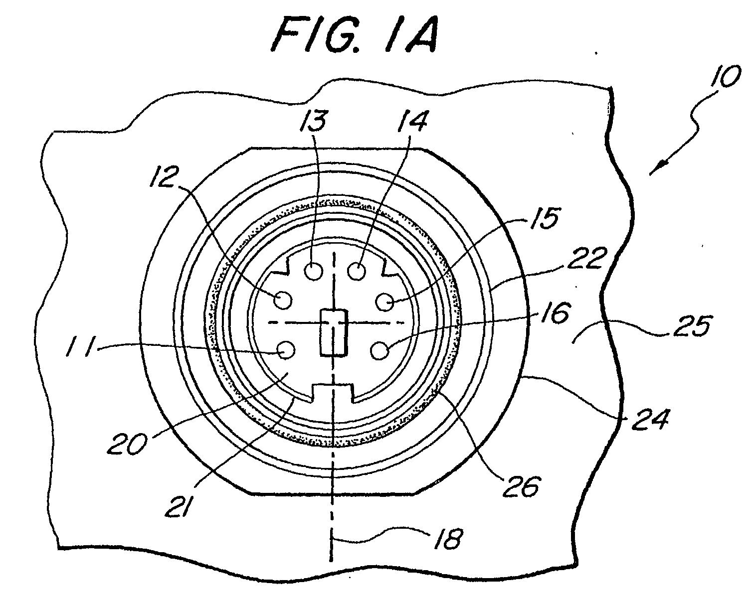
- FIG. 1A illustrates the plan view of the connector receptacle 10
- Figure 1B illustrates the partially cut-away side view of the same connector receptacle.
- a plurality of electrical connection sockets 11, 12, 13, 14, 15 and 16 are located concentrically about a center-line 18 of the connector 10.
- the sockets 11 - 16 are located within an insulator 20, which is surrounded by a conductive sleeve 21.
- the insulator 20 and sleeve 21 are both concentric with the center-line 18.
- the connector is enclosed within a housing 22 having a shoulder 23.
- the sleeve 21,which is made of aluminum or stainless steel, is connected to a ground pin 50 as shown in Figure 1B.
- the housing 22 has threaded thereon a locking nut 24, which secures the connector 10 to a support 25.
- a first “O" ring 26 is located inside between the sleeve 21 and the housing 22, and may be attached to the surface of the housing as shown by means of epoxy.
- the "O” ring 26 may be made of silicone or Teflon or butyl rubber. However, I have discovered that butyl rubber is a preferred material to use, which "O" ring may be acquired from the Parker Seal Company of Cleveland, Ohio.
- a second "O" ring 27 is located outside the housing and on a mating surface of the shoulder 23.
- the housing 22 may be fabricated with aluminum or cast aluminum or stainless steel.
- connection pins 30, 31, 32, 33, 34 and 35 are disposed for electrical connection or, as shown, receipt by vias in a circuit board 36.
- the ground pin 50 is located in the center of the receptacle and is also received by a via in the circuit board 36. To help maintain the watertight integrity of the connector receptacle 10, the bottom thereof is sealed at a surface 37.
- FIG. 2A a plan view of a male connector 40 is shown adapted for use with the connector receptacle 10 and includes a straight "pig tail" 39.
- the connector 40 includes pins 41, 42, 43, 44, 45 and 46, which mate with the sockets 11 - 16 of the connector 10.
- the pins 41 - 46 are within a protective sleeve 47.
- the protective sleeve 47 is equi-diameter with the "O" ring 26 ( Figure 1), and when the connector 40 is joined with the connector receptacle 10 a watertight seal is formed.
- This same male connector 40 is shown in a partially cut-away side view in Figure 2B, wherein like reference numerals are used.
- FIG. 3A a plan view of another type of male connector 50 is shown for use with the connector receptacle 10 and includes a right angle "pig tail" 49.
- the connector 50 includes pins 51, 52, 53, 54, 55 and 56, which mate with the sockets 11 - 16 of the connector 10.
- the pins 51 - 56 are within a protective sleeve 57.
- the protective sleeve 57 is equi-diameter with the "O" ring 26 ( Figure 1), and when the connector 50 is joined together with the connector receptacle 10 a watertight seal is formed.
- This same male connector 50 is shown in a partially cut-away side view in Figure 3B, wherein like reference numerals are used.
Landscapes
- Connector Housings Or Holding Contact Members (AREA)
Abstract
Description
Claims (20)
- An electrical connector forming a watertight seal once connected, said connector comprising:a. a receptacle formed within a first housing and having a plurality of electrically conductive sockets disposed in an insulator for receiving electrically conductive pins, said insulator being surrounded by a sleeve;b. a plug formed within a second housing and having a plurality of electrically conductive pins; and,c. an "O" ring disposed between said sleeve and said second housing and having a diameter substantially equal to the diameter of said first housing, whereby said "O" ring forms a watertight seal between said receptacle and said plug.
- The electrical connector as in Claim 1 wherein said receptacle includes a plurality of connecting pins disposed on the end opposite the location of said plurality of sockets.
- The electrical connector as in Claim 2 wherein said plurality of connecting pins are adapted for receipt by and disposed for an electrical connection with a circuit board.
- The electrical connector as in Claim 1 wherein said first housing is formed of aluminum.
- The electrical connector as in any of the preceding claims, wherein said insulator within said sleeve is formed of non-conductive plastic.
- The electrical connector as in any of the preceding claims, wherein said sleeve is made of aluminum and coupled to a grounding pin.
- The electrical connector as in any of the preceding claims, wherein said plug is formed with a pig tail at right angles to said receptacle.
- The electrical connector as in any of claims 1 to 6, wherein said plug is formed with a pig tail 6, aligned with said plug is formed with a pig tail aligned with said receptacle.
- The electrical connector as in any of the preceding claims, wherein said first housing includes threads for receiving a locking nut thereon for securing said receptacle to a mounting surface.
- A cable connector for making a plurality of electrical connections in a watertight environment, said connector comprising:a. a receptacle formed within a first insulating housing and having a plurality of electrically conductive sockets disposed in an insulator for receiving electrically conductive pins, said insulator being surrounded by a conductive sleeve coupled to ground potential;b. a plug formed within a second insulating housing and having a plurality of electrically conductive pins no greater in number than the number of said electrically conductive sockets; and,c. an insulating "O" ring disposed between said sleeve and said first insulating housing and having a diameter equal to the diameter of said second insulating housing, whereby said "O" ring forms a watertight seal between said receptacle and said plug.
- The cable connector as in Claim 10 wherein said first and second housing are made of a non-conductive plastic.
- The cable connector as in claim 10 or claim 11 wherein said receptacle includes a plurality of connecting pins disposed on the end opposite the location of said plurality of sockets.
- The cable connector as in Claim 10 wherein said plurality of connecting pins are adapted for receipt by and disposed for an electrical connection with a circuit board.
- The cable connector as in any of claims 10 to 13 wherein said insulator within said sleeve is formed of non-conductive plastic.
- The cable connector as in any of claims 10 to 14 wherein said sleeve is made of aluminum and coupled to a grounding pin.
- The cable connector as in any of claims 10 to 15 wherein said plug is formed with a pig tail at right angles to said receptacle.
- The cable connector as in any of claims 10 to 15 wherein said plug is formed with a pig tail aligned with said receptacle.
- The cable connector as in any of claims 10 to 17 wherein said first housing includes threads for receiving a locking nut thereon for securing said receptacle to a mounting surface.
- A cable connector for making a plurality of electrical connections in a watertight environment, said connector comprising:a. a receptacle formed within a first housing and having a plurality of electrically conductive sockets disposed in an insulator for receiving electrically conductive pins and having a plurality of connecting pins disposed on the end opposite the location of said plurality of sockets;b. a plug formed within a second insulating housing and having a plurality of electrically conductive pins no greater in number than the number of said electrically conductive sockets; and,c. an insulating "O" ring disposed between said sleeve and said first insulating housing and having a diameter equal to the diameter of said second insulating housing, whereby said "O" ring forms a watertight seal between said receptacle and said plug.
- The cable connector as in Claim 19 wherein said plurality of connecting pins are adapted for receipt by and disposed for an electrical connection with a circuit board.
Applications Claiming Priority (2)
| Application Number | Priority Date | Filing Date | Title |
|---|---|---|---|
| US09/860,986 US6464523B1 (en) | 2001-05-18 | 2001-05-18 | Watertight electrical cable connector |
| US860986 | 2001-05-18 |
Publications (3)
| Publication Number | Publication Date |
|---|---|
| EP1261076A2 true EP1261076A2 (en) | 2002-11-27 |
| EP1261076A3 EP1261076A3 (en) | 2003-11-05 |
| EP1261076B1 EP1261076B1 (en) | 2005-09-14 |
Family
ID=25334561
Family Applications (1)
| Application Number | Title | Priority Date | Filing Date |
|---|---|---|---|
| EP02253433A Expired - Lifetime EP1261076B1 (en) | 2001-05-18 | 2002-05-16 | Watertight electrical cable connector |
Country Status (4)
| Country | Link |
|---|---|
| US (1) | US6464523B1 (en) |
| EP (1) | EP1261076B1 (en) |
| KR (1) | KR20020089148A (en) |
| DE (1) | DE60206101T2 (en) |
Cited By (1)
| Publication number | Priority date | Publication date | Assignee | Title |
|---|---|---|---|---|
| KR20020089148A (en) * | 2001-05-18 | 2002-11-29 | 노스롭 그루만 코포레이션 | Watertight electrical cable connector |
Families Citing this family (10)
| Publication number | Priority date | Publication date | Assignee | Title |
|---|---|---|---|---|
| RU2260231C1 (en) * | 2004-04-13 | 2005-09-10 | ОБЩЕСТВО С ОГРАНИЧЕННОЙ ОТВЕТСТВЕННОСТЬЮ "ЗАПАДНО-УРАЛЬСКОЕ ОБЩЕСТВО РАЗВИТИЯ ПРИКЛАДНЫХ ИССЛЕДОВАНИЙ ЗУРО, Лтд." | Cable connector for use in conducting medium |
| US7465182B1 (en) | 2007-11-30 | 2008-12-16 | Mcdonald Michael | Electrical cord connector assembly |
| US7632145B1 (en) * | 2009-01-26 | 2009-12-15 | Advanced-Connectek Inc. | Receptacle connector |
| US7959454B2 (en) * | 2009-07-23 | 2011-06-14 | Teledyne Odi, Inc. | Wet mate connector |
| US8968018B2 (en) | 2009-08-05 | 2015-03-03 | Teledyne Instruments, Inc. | Electrical penetrator assembly |
| EP2462312B1 (en) * | 2009-08-05 | 2022-08-17 | Teledyne Instruments, Inc. | Electrical penetrator assembly |
| US8430686B2 (en) * | 2010-12-03 | 2013-04-30 | Harris Corporation | Anti-rotation panel mount audio fill connector |
| CN205812284U (en) * | 2016-03-10 | 2016-12-14 | 中兴通讯股份有限公司 | Base station box |
| DE102017115914B3 (en) * | 2017-07-14 | 2018-10-31 | HARTING Electronics GmbH | Printed circuit board connector with a screen element |
| CN111499860A (en) * | 2020-05-09 | 2020-08-07 | 电子科技大学 | Poly (arylene ether nitrile) production process for efficiently recovering N-methylpyrrolidone solvent |
Family Cites Families (14)
| Publication number | Priority date | Publication date | Assignee | Title |
|---|---|---|---|---|
| GB725021A (en) * | 1952-05-07 | 1955-03-02 | Titeflex Inc | Shielded waterproof electrical plug and socket connectors |
| GB735937A (en) * | 1952-06-16 | 1955-08-31 | Simmonds And Stokes Niphan Ltd | Improvements relating to electric cable couplings |
| US3986765A (en) * | 1975-02-07 | 1976-10-19 | Amp Incorporated | Power cord connector |
| US4291932A (en) * | 1980-03-25 | 1981-09-29 | The United States Of America As Represented By The Secretary Of The Navy | Electrical connector receptacle assembly |
| FR2527389A1 (en) * | 1982-05-19 | 1983-11-25 | Souriau & Cie | IMPROVEMENTS IN CONNECTION WITH ELECTRICAL CONNECTORS, IN PARTICULAR FOR USE IN A LIQUID MEDIUM, IN PARTICULAR UNDER PRESSURE |
| US4738628A (en) * | 1986-09-29 | 1988-04-19 | Cooper Industries | Grounded metal coupling |
| US5240424A (en) * | 1990-03-08 | 1993-08-31 | Daiichi Denshi Kogyo Kabushiki Kaisha | Electrical connector |
| US5246383A (en) * | 1990-09-17 | 1993-09-21 | Raychem Corporation | Gel filled electrical connector |
| JPH07254459A (en) * | 1994-03-17 | 1995-10-03 | Mutsuo Hanzawa | Waterproof connecting jack for antenna |
| JP3060359B2 (en) * | 1994-04-06 | 2000-07-10 | 矢崎総業株式会社 | Electrical connector |
| DE19613228B4 (en) * | 1996-04-02 | 2006-07-27 | Escha Bauelemente Gmbh | Electrical plug connection, in particular plug part for an electrical plug connection |
| US5902150A (en) * | 1997-01-09 | 1999-05-11 | Illinois Tool Works Inc | Connector for a power supply |
| JP3313329B2 (en) * | 1998-10-21 | 2002-08-12 | ヒロセ電機株式会社 | Multi-pole waterproof connector |
| US6464523B1 (en) * | 2001-05-18 | 2002-10-15 | Northrop Grumman Corporation | Watertight electrical cable connector |
-
2001
- 2001-05-18 US US09/860,986 patent/US6464523B1/en not_active Expired - Lifetime
-
2002
- 2002-05-16 DE DE60206101T patent/DE60206101T2/en not_active Expired - Lifetime
- 2002-05-16 KR KR1020020026955A patent/KR20020089148A/en not_active Ceased
- 2002-05-16 EP EP02253433A patent/EP1261076B1/en not_active Expired - Lifetime
Cited By (1)
| Publication number | Priority date | Publication date | Assignee | Title |
|---|---|---|---|---|
| KR20020089148A (en) * | 2001-05-18 | 2002-11-29 | 노스롭 그루만 코포레이션 | Watertight electrical cable connector |
Also Published As
| Publication number | Publication date |
|---|---|
| DE60206101D1 (en) | 2005-10-20 |
| DE60206101T2 (en) | 2006-06-08 |
| US6464523B1 (en) | 2002-10-15 |
| KR20020089148A (en) | 2002-11-29 |
| EP1261076B1 (en) | 2005-09-14 |
| EP1261076A3 (en) | 2003-11-05 |
Similar Documents
| Publication | Publication Date | Title |
|---|---|---|
| US7338305B2 (en) | BNC connector having visual indication | |
| US2755331A (en) | Co-axial cable fitting | |
| US5368499A (en) | Multi-lead electric plug connector | |
| US9761972B2 (en) | Radio frequency connector and assembly having micro-via radial interconnect | |
| US5401175A (en) | Magnetic coaxial connector | |
| US4099825A (en) | Coaxial adapter | |
| US6126482A (en) | Right angle coaxial cable connector | |
| US6464523B1 (en) | Watertight electrical cable connector | |
| US20030040213A1 (en) | Connector assembly having visual indicator | |
| JP2008530754A5 (en) | ||
| US5857867A (en) | Hermaphroditic coaxial connector | |
| CA2498469A1 (en) | Compression multi-tap 360 degree rotating connect/disconnect terminal | |
| US4867692A (en) | Electrical connector high current surge protection | |
| KR101810127B1 (en) | Wire connecting apparatus for high voltage connector | |
| US4598969A (en) | Termination means | |
| EP0532662A1 (en) | Connector. | |
| US5490789A (en) | Molded connector with internal grounding | |
| US8425259B2 (en) | Vandal proof NMO antenna mount | |
| JP4951665B2 (en) | connector | |
| US7438601B2 (en) | Connector | |
| EP0849835A3 (en) | Electrical connectors and connecting parts therefor | |
| US20230028369A1 (en) | Rolling-ball tilt switch | |
| JP7400647B2 (en) | electrical connectors | |
| US20020106936A1 (en) | Connection element for connecting a semi-rigid coaxial conductor | |
| US3959760A (en) | Dry type instrument transformer with potential tap and connector therefor |
Legal Events
| Date | Code | Title | Description |
|---|---|---|---|
| PUAI | Public reference made under article 153(3) epc to a published international application that has entered the european phase |
Free format text: ORIGINAL CODE: 0009012 |
|
| AK | Designated contracting states |
Kind code of ref document: A2 Designated state(s): AT BE CH CY DE DK ES FI FR GB GR IE IT LI LU MC NL PT SE TR |
|
| AX | Request for extension of the european patent |
Free format text: AL;LT;LV;MK;RO;SI |
|
| PUAL | Search report despatched |
Free format text: ORIGINAL CODE: 0009013 |
|
| AK | Designated contracting states |
Kind code of ref document: A3 Designated state(s): AT BE CH CY DE DK ES FI FR GB GR IE IT LI LU MC NL PT SE TR |
|
| AX | Request for extension of the european patent |
Extension state: AL LT LV MK RO SI |
|
| RIC1 | Information provided on ipc code assigned before grant |
Ipc: 7H 01R 13/52 B Ipc: 7H 01R 13/523 A |
|
| 17P | Request for examination filed |
Effective date: 20040422 |
|
| AKX | Designation fees paid |
Designated state(s): DE FR GB IT |
|
| 17Q | First examination report despatched |
Effective date: 20040707 |
|
| GRAP | Despatch of communication of intention to grant a patent |
Free format text: ORIGINAL CODE: EPIDOSNIGR1 |
|
| GRAS | Grant fee paid |
Free format text: ORIGINAL CODE: EPIDOSNIGR3 |
|
| GRAA | (expected) grant |
Free format text: ORIGINAL CODE: 0009210 |
|
| AK | Designated contracting states |
Kind code of ref document: B1 Designated state(s): DE FR GB IT |
|
| REG | Reference to a national code |
Ref country code: GB Ref legal event code: FG4D |
|
| REF | Corresponds to: |
Ref document number: 60206101 Country of ref document: DE Date of ref document: 20051020 Kind code of ref document: P |
|
| ET | Fr: translation filed | ||
| PLBE | No opposition filed within time limit |
Free format text: ORIGINAL CODE: 0009261 |
|
| STAA | Information on the status of an ep patent application or granted ep patent |
Free format text: STATUS: NO OPPOSITION FILED WITHIN TIME LIMIT |
|
| 26N | No opposition filed |
Effective date: 20060615 |
|
| PGFP | Annual fee paid to national office [announced via postgrant information from national office to epo] |
Ref country code: IT Payment date: 20070524 Year of fee payment: 6 |
|
| PG25 | Lapsed in a contracting state [announced via postgrant information from national office to epo] |
Ref country code: IT Free format text: LAPSE BECAUSE OF NON-PAYMENT OF DUE FEES Effective date: 20080516 |
|
| REG | Reference to a national code |
Ref country code: GB Ref legal event code: 732E Free format text: REGISTERED BETWEEN 20110526 AND 20110601 |
|
| PGFP | Annual fee paid to national office [announced via postgrant information from national office to epo] |
Ref country code: FR Payment date: 20110607 Year of fee payment: 10 |
|
| PGFP | Annual fee paid to national office [announced via postgrant information from national office to epo] |
Ref country code: GB Payment date: 20110520 Year of fee payment: 10 |
|
| PGFP | Annual fee paid to national office [announced via postgrant information from national office to epo] |
Ref country code: DE Payment date: 20110520 Year of fee payment: 10 |
|
| REG | Reference to a national code |
Ref country code: FR Ref legal event code: TP Owner name: NORTHROP GRUMMAN SYSTEMS CORPORATION, US Effective date: 20120314 |
|
| GBPC | Gb: european patent ceased through non-payment of renewal fee |
Effective date: 20120516 |
|
| REG | Reference to a national code |
Ref country code: DE Ref legal event code: R082 Ref document number: 60206101 Country of ref document: DE Representative=s name: HAUCK PATENT- UND RECHTSANWAELTE, DE |
|
| REG | Reference to a national code |
Ref country code: FR Ref legal event code: ST Effective date: 20130131 |
|
| REG | Reference to a national code |
Ref country code: DE Ref legal event code: R119 Ref document number: 60206101 Country of ref document: DE Effective date: 20121201 |
|
| REG | Reference to a national code |
Ref country code: DE Ref legal event code: R081 Ref document number: 60206101 Country of ref document: DE Owner name: NORTHROP GRUMMAN SYSTEMS CORPORATION (N.D.GES., US Free format text: FORMER OWNER: NORTHROP GRUMMAN CORP., WOODLAND HILLS, US Effective date: 20130205 Ref country code: DE Ref legal event code: R082 Ref document number: 60206101 Country of ref document: DE Representative=s name: HAUCK PATENT- UND RECHTSANWAELTE, DE Effective date: 20130205 Ref country code: DE Ref legal event code: R081 Ref document number: 60206101 Country of ref document: DE Owner name: NORTHROP GRUMMAN SYSTEMS CORPORATION (N.D.GES., US Free format text: FORMER OWNER: NORTHROP GRUMMAN CORP., WOODLAND HILLS, CALIF., US Effective date: 20130205 Ref country code: DE Ref legal event code: R082 Ref document number: 60206101 Country of ref document: DE Representative=s name: HAUCK PATENTANWALTSPARTNERSCHAFT MBB, DE Effective date: 20130205 |
|
| PG25 | Lapsed in a contracting state [announced via postgrant information from national office to epo] |
Ref country code: FR Free format text: LAPSE BECAUSE OF NON-PAYMENT OF DUE FEES Effective date: 20120531 Ref country code: GB Free format text: LAPSE BECAUSE OF NON-PAYMENT OF DUE FEES Effective date: 20120516 |
|
| PG25 | Lapsed in a contracting state [announced via postgrant information from national office to epo] |
Ref country code: DE Free format text: LAPSE BECAUSE OF NON-PAYMENT OF DUE FEES Effective date: 20121201 |