EP1260952A2 - Pulse transmission line control system - Google Patents
Pulse transmission line control system Download PDFInfo
- Publication number
- EP1260952A2 EP1260952A2 EP02011258A EP02011258A EP1260952A2 EP 1260952 A2 EP1260952 A2 EP 1260952A2 EP 02011258 A EP02011258 A EP 02011258A EP 02011258 A EP02011258 A EP 02011258A EP 1260952 A2 EP1260952 A2 EP 1260952A2
- Authority
- EP
- European Patent Office
- Prior art keywords
- pulse
- microcomputer
- sub
- microcomputers
- switch
- Prior art date
- Legal status (The legal status is an assumption and is not a legal conclusion. Google has not performed a legal analysis and makes no representation as to the accuracy of the status listed.)
- Withdrawn
Links
Images


Classifications
-
- H—ELECTRICITY
- H04—ELECTRIC COMMUNICATION TECHNIQUE
- H04Q—SELECTING
- H04Q9/00—Arrangements in telecontrol or telemetry systems for selectively calling a substation from a main station, in which substation desired apparatus is selected for applying a control signal thereto or for obtaining measured values therefrom
-
- G—PHYSICS
- G08—SIGNALLING
- G08C—TRANSMISSION SYSTEMS FOR MEASURED VALUES, CONTROL OR SIMILAR SIGNALS
- G08C23/00—Non-electrical signal transmission systems, e.g. optical systems
- G08C23/04—Non-electrical signal transmission systems, e.g. optical systems using light waves, e.g. infrared
Definitions
- the present invention relates to a pulse transmission line control system capable of selecting and controlling a transmission of an electrical signal pulse generated from an infrared code sent by an infrared remote control unit to a plurality of microcomputers that decode the electrical signal pulse and process the electrical signal pulse according to the infrared code.
- an apparatus will be described below that includes microcomputers having the function (hereinafter called “system for receiving an infrared remote control unit code pulse”) of decoding an electrical signal pulse (hereinafter called “an infrared remote control unit code pulse”) generated from an infrared code sent by an infrared remote control unit.
- system for receiving an infrared remote control unit code pulse an electrical signal pulse
- an infrared remote control unit code pulse generated from an infrared code sent by an infrared remote control unit.
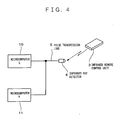
- This apparatus is a combination of a new microcomputer G 10 and an existing microcomputer H 11.
- an infrared ray detector 4 receives and converts the infrared code into an infrared remote control unit code pulse.
- the infrared remote control unit code pulse is transmitted to the microcomputers G 10 and H 11 over a pulse transmission line 5. Then, the microcomputer G 10 or H 11 decodes the infrared remote control unit code pulse to perform an operation requested by the infrared remote control unit 3 (requested by an operator).
- the present invention has been achieved in order to solve the problem and it is an object of the present invention to provide a pulse transmission line control system so that in an apparatus including a plurality of microcomputers each having a system for receiving an infrared remote control unit code pulse, one of the plurality of microcomputers has a function of controlling on/off operation of a switch and the other microcomputers are connected to a pulse transmission line through the switch, and the switch is controlled to transmit the infrared remote control unit code pulse only to one or more of the microcomputers that perform a process required for operation, thereby preventing a malfunction of the microcomputers.
- the pulse transmission line control system is a system including a main microcomputer and a sub-microcomputer for performing a process according to an infrared code sent from an infrared remote control unit.
- the system includes an infrared ray detector for receiving the infrared code and converting the received infrared code into an electrical signal pulse, a pulse transmission line for transmitting the pulse to the main microcomputer and the sub-microcomputer, and a switch for connecting the sub-microcomputer to the pulse transmission line, wherein the main microcomputer selects and controls the switch according to whether or not transmission of the pulse to the sub-microcomputer is permitted and the pulse is transmitted to the sub-microcomputer when the transmission is permitted.
- the pulse transmission line control system is characterized in that a plurality of the sub-microcomputers are provided, each of the sub-microcomputers being provided with the switch, and the main microcomputer selects and controls the switch so that the pulse is transmitted only to one or more of the sub-microcomputers that perform a process required for operation.
- the pulse transmission control system is characterized in that when the main microcomputer turns on the switch according to the received infrared code, the main microcomputer turns on the switch after the input of a pulse generated from the infrared code is completed.
- a switch or switches can be controlled so that the infrared remote control unit code pulse is transmitted only to one or more of the microcomputers that perform a process required for operation and, as a result, a malfunction of the microcomputers can be prevented.
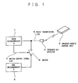
- FIG. 1 is a block diagram of an apparatus including microcomputers having a system for receiving an infrared remote control unit code pulse according to a first embodiment.
- reference numbers 1 and 2 denote a main microcomputer A and a sub-microcomputer B, respectively, having the system for receiving an infrared remote control unit code pulse.
- a main microcomputer A 1 is a new microcomputer and a sub-microcomputer B 2 is an existing microcomputer.
- Reference number 3 denotes an infrared remote control unit that sends an infrared code corresponding to a request from an operator.
- Reference number 4 denotes an infrared ray detector for receiving the infrared code from the infrared remote control unit and converting it into an infrared remote control unit code pulse.
- Reference number 5 denotes a pulse transmission line for transmitting the infrared remote control unit code pulse and 6 denotes a switch for switching on/off the pulse transmission line 5 connected to the sub-microcomputer B 2.
- the main microcomputer A 1 When the switch 6 is turned to an on-state, the main microcomputer A 1 is connected in parallel with the sub-microcomputer B 2, as shown in FIG. 1.
- Reference number 7 denotes a switch control signal line for transmitting a control signal from the main microcomputer A 1 to the switch 6.
- the main microcomputer A 1 has the function of controlling the switch 6 according to an internal state transition and is responsible for controlling the entire apparatus in executing an operation requested by the operator.
- the main microcomputer A 1 If the main microcomputer A 1 permits an infrared remote control unit code pulse to be provided to the sub-microcomputer B 2, the main microcomputer A 1 sends an ON control signal to the switch 6 to bring the pulse transmission line 5 connected to the sub-microcomputer B 2 into conduction. Because the pulse transmission line 5 is in the conduction state, the infrared remote control unit code pulse sent from the infrared ray detector 4 is transmitted to the sub-microcomputer B 2.
- the main microcomputer A 1 sends an OFF control signal to the switch 6 to block the pulse transmission line 5 connected to the sub-microcomputer B 2. Because the pulse transmission line 5 is blocked, the infrared remote control unit code pulse from the infrared ray detector 4 is not transmitted to the sub-microcomputer B 2.
- FIG. 2 is a block diagram of an apparatus including microcomputers having a system for receiving an infrared remote control unit code pulse according to a second embodiment.
- Components having the same configuration as those in the first embodiment described above are labeled with the same reference numbers and the description of which will be omitted.
- a main microcomputer C 8 and a sub-microcomputers D, E, and F have a system for receiving an infrared remote control unit code pulse.
- the main microcomputer C 8 is a new microcomputer and the sub-microcomputers DEF 9 are existing microcomputers.
- Switches 6 are used for switching on/off a pulse transmission line 5 connected to the sub-microcomputers DEF 9.
- the main microcomputer C 8 When a switch 6 is turned on, the main microcomputer C 8 is connected in parallel with the one of the sub-microcomputers DEF 9 that is associated with the switch, as shown in FIG. 2.
- the main microcomputer C 8 has the function of controlling the switch 6 according to an internal state transition and is responsible for controlling the entire apparatus in executing an operation requested by the operator.
- the main microcomputer C 8 If the main microcomputer C 8 permits an infrared remote control unit code pulse to be provided to one of the sub-microcomputers DEF 9, the main microcomputer C 8 sends an ON control signal to the associated switch 6 to bring the pulse transmission line 5 to the sub-microcomputer DEF 9 into conduction. Because the pulse transmission line 5 is in the conduction state, the infrared remote control unit code pulse sent from the infrared ray detector 4 is transmitted to the sub-microcomputer DEF 9.
- the main microcomputer C 8 If the main microcomputer C 8 does not permit the infrared remote control unit code pulse to be provided to on or more of the sub-microcomputers DEF 9, the main microcomputer C 8 sends an OFF control signal to the associated switch(es) 6 to block the pulse transmission line 5 connected to the sub-microcomputers DEF 9. Because the pulse transmission line 5 is blocked, the infrared remote control unit code pulse from the infrared ray detector 4 is not transmitted to the sub-microcomputer(s) DEF 9.
- the apparatus in the second embodiment may be any apparatus that uses a plurality of microcomputers having the system for receiving an infrared remote control unit code pulse but not all of the plurality of microcomputers are required to have the system for receiving an infrared remote control unit code pulse.
- the number of existing microcomputers having the system for receiving an infrared remote control unit code pulse is not limited to three.
- various controls can be performed by combining switches in different ways or controlling the switches separately.
- FIGS. 1 and 3 a process performed by a main microcomputer having the switch control function in the first and second embodiments will be described below in which the main microcomputer turns on a switch 6 while infrared remote control unit code pulses are being inputted in series into the main microcomputer.
- the microcomputer A 1 determines whether the switch 6 should be turned on or off, based on an internal state transition that corresponds to an infrared remote control unit code pulse. When it determines that the switch 6 should be turned off, it sends an OFF control signal to the switch 6 at step 2. When it determines that the switch 6 should be turned on, the process proceeds to step 3.
- the main microcomputer A1 checks the current state of the switch 6. When the switch 6 is in the off-state, the process proceeds to step 4 in order to turn it on. When the switch 6 is in the on-state at step 3, the on-state is maintained.
- the main microcomputer A 1 checks to see whether the input of the transmitted infrared remote control unit code pulse has been completed. If the input of the infrared remote control unit code pulse into the main microcomputer A 1 has not been completed yet, turning on the switch 6 would cause the same infrared remote control unit code pulse as that being inputted into the main microcomputer A 1 to also be inputted into a sub-microcomputer B 2 and, as a result, the sub-microcomputer B2 can perform an unintended operation. Therefore, if the input of the infrared remote control unit code pulse into the main microcomputer A 1 has not been completed yet, it does not turn on the switch 6 but keeps the switch 6 in the off-state. After the main microcomputer A 1 determines that the input of the infrared remote control unit code pulse into the main microcomputer A 1 has been completed, it proceeds to step 5 to turn on the switch 6.
- the function of controlling the on/off states of one of the plurality of microcomputers is added to one of the plurality of microcomputers in such a way that the other microcomputers are connected to a pulse transmission line through the switch, and the switch is controlled so that an infrared remote control unit code pulse is transmitted only to a microcomputer that performs a process required for operating the apparatus.
- the present invention can prevent a malfunction of the microcomputers and especially advantageous in apparatuses where existing microcomputers are exploited.
Landscapes
- Physics & Mathematics (AREA)
- General Physics & Mathematics (AREA)
- Engineering & Computer Science (AREA)
- Computer Networks & Wireless Communication (AREA)
- Selective Calling Equipment (AREA)
Abstract
Description
Claims (3)
- A system including a main microcomputer and a sub-microcomputer for performing a process according to an infrared code sent from an infrared remote control unit, comprising:wherein said main microcomputer selects and controls said switch according to whether or not transmission of said pulse to said sub-microcomputer is permitted and said pulse is transmitted to said sub-microcomputer when the transmission is permitted.an infrared ray detector for receiving said infrared code and converting said received infrared code into an electrical signal pulse;a pulse transmission line for transmitting said pulse to said main microcomputer and said sub-microcomputer; anda switch for connecting said sub-microcomputer to said pulse transmission line,
- The pulse transmission line control system according to claim 1, wherein a plurality of said sub-microcomputers are provided, each of said sub-microcomputers being provided with said switch, and said main microcomputer selects and controls said switches so that said pulse is transmitted only to one or more of said sub-microcomputers that perform a process required for operation.
- The pulse transmission control system according to claim 1 or claim 2, wherein when said main microcomputer turns on said switch according to the received infrared code, said main microcomputer turns on said switch after the input of a pulse generated from said infrared code is completed.
Applications Claiming Priority (2)
| Application Number | Priority Date | Filing Date | Title |
|---|---|---|---|
| JP2001154711A JP4859284B2 (en) | 2001-05-24 | 2001-05-24 | Pulse transmission line control system |
| JP2001154711 | 2001-05-24 |
Publications (2)
| Publication Number | Publication Date |
|---|---|
| EP1260952A2 true EP1260952A2 (en) | 2002-11-27 |
| EP1260952A3 EP1260952A3 (en) | 2003-11-19 |
Family
ID=18999013
Family Applications (1)
| Application Number | Title | Priority Date | Filing Date |
|---|---|---|---|
| EP02011258A Withdrawn EP1260952A3 (en) | 2001-05-24 | 2002-05-22 | Pulse transmission line control system |
Country Status (6)
| Country | Link |
|---|---|
| US (1) | US6678763B2 (en) |
| EP (1) | EP1260952A3 (en) |
| JP (1) | JP4859284B2 (en) |
| KR (1) | KR100824340B1 (en) |
| MY (1) | MY122905A (en) |
| TW (1) | TWI228936B (en) |
Cited By (1)
| Publication number | Priority date | Publication date | Assignee | Title |
|---|---|---|---|---|
| KR100824340B1 (en) * | 2001-05-24 | 2008-04-22 | 마츠시타 덴끼 산교 가부시키가이샤 | Pulse transmission path control system |
Family Cites Families (15)
| Publication number | Priority date | Publication date | Assignee | Title |
|---|---|---|---|---|
| JPS5951793B2 (en) * | 1978-06-08 | 1984-12-15 | 株式会社リコー | Data collection method |
| JPH07105895B2 (en) * | 1986-06-02 | 1995-11-13 | ソニー株式会社 | Electronics |
| JPH02215296A (en) * | 1989-02-16 | 1990-08-28 | Yamaha Corp | Remote controller |
| FI84537C (en) * | 1990-01-18 | 1991-12-10 | Nokia Mobile Phones Ltd | DIVERSITETSANTENNKOPPLING FOER EN DIGITAL MOBILTELEFON. |
| KR960001834Y1 (en) * | 1990-11-08 | 1996-02-28 | 대우전자 주식회사 | Input signal automatic switching circuit |
| US5473318A (en) * | 1992-01-10 | 1995-12-05 | Active Control Technology Inc. | Secure remote control system with receiver controlled to add and delete identity codes |
| US5486782A (en) * | 1994-09-27 | 1996-01-23 | International Business Machines Corporation | Transmission line output driver |
| US6359547B1 (en) * | 1994-11-15 | 2002-03-19 | William D. Denison | Electronic access control device |
| KR0173051B1 (en) * | 1995-10-06 | 1999-03-30 | 양승택 | Modular distributed controller and crossbar connection configuration control method in crossbar switching system |
| US6421390B1 (en) * | 1995-12-26 | 2002-07-16 | The Regents Of The University Of California | High-speed pulse-shape generator, pulse multiplexer |
| KR980007812A (en) * | 1996-06-17 | 1998-03-30 | 조희재 | Multiple set remote control system and method |
| JP3445928B2 (en) * | 1997-11-25 | 2003-09-16 | アルパイン株式会社 | Remote control circuit |
| JP2000113576A (en) * | 1998-10-05 | 2000-04-21 | Nippon Columbia Co Ltd | Reproducing device |
| KR20010001501A (en) * | 1999-06-04 | 2001-01-05 | 김원식 | Unity System Using Remocon And Driving Method Thereof |
| JP4859284B2 (en) * | 2001-05-24 | 2012-01-25 | パナソニック株式会社 | Pulse transmission line control system |
-
2001
- 2001-05-24 JP JP2001154711A patent/JP4859284B2/en not_active Expired - Fee Related
-
2002
- 2002-04-25 KR KR1020020022730A patent/KR100824340B1/en not_active Expired - Fee Related
- 2002-05-14 TW TW091110009A patent/TWI228936B/en not_active IP Right Cessation
- 2002-05-16 US US10/145,693 patent/US6678763B2/en not_active Expired - Fee Related
- 2002-05-21 MY MYPI20021877A patent/MY122905A/en unknown
- 2002-05-22 EP EP02011258A patent/EP1260952A3/en not_active Withdrawn
Cited By (1)
| Publication number | Priority date | Publication date | Assignee | Title |
|---|---|---|---|---|
| KR100824340B1 (en) * | 2001-05-24 | 2008-04-22 | 마츠시타 덴끼 산교 가부시키가이샤 | Pulse transmission path control system |
Also Published As
| Publication number | Publication date |
|---|---|
| KR20020090116A (en) | 2002-11-30 |
| JP4859284B2 (en) | 2012-01-25 |
| EP1260952A3 (en) | 2003-11-19 |
| KR100824340B1 (en) | 2008-04-22 |
| US20020178308A1 (en) | 2002-11-28 |
| MY122905A (en) | 2006-05-31 |
| US6678763B2 (en) | 2004-01-13 |
| JP2002354562A (en) | 2002-12-06 |
| TWI228936B (en) | 2005-03-01 |
Similar Documents
| Publication | Publication Date | Title |
|---|---|---|
| KR960004507B1 (en) | Remote control system | |
| US6678763B2 (en) | Pulse transmission line control system | |
| JP6431502B2 (en) | Control device, program, and control method | |
| JPH10145266A (en) | Remote controller using power line | |
| KR19980059090A (en) | Control device capable of bidirectional communication | |
| CN114067547A (en) | Method for coupling a remote control and an electronic device | |
| JPH11168779A (en) | Controller and method for remote control and record medium with control program for remote control recorded therein | |
| KR0138590B1 (en) | Method for initializing the key-system | |
| JP2639340B2 (en) | Printer with network function | |
| JPH11312009A (en) | Remote control device, device control device, remote control system, and remote control system control method | |
| JP2985795B2 (en) | Parental lock function control system | |
| KR100536695B1 (en) | Method for processing toggle signal of combo system | |
| KR200357896Y1 (en) | Mouse having receiver for remote control | |
| KR20060059028A (en) | Wireless on / off switch using on / off controller and its operation method | |
| KR101093497B1 (en) | Remote Control of Superconducting Tokamak Device | |
| JP2002252888A (en) | Transmitting device, electronic device body remotely controlled thereby, and header switching method | |
| KR0170151B1 (en) | Operating method of bidirectional remote controller | |
| JPS6353759B2 (en) | ||
| KR19980027707A (en) | How to lock electronic products and remote controller with remote controller lock function | |
| KR970058218A (en) | Simple operation of remote controller | |
| HK1232006A1 (en) | Method for coupling remote control and electronic device | |
| JPS62196991A (en) | Television control system | |
| JPH09281936A (en) | Display control system | |
| JPH11288652A (en) | Breaker electrical operating device | |
| JP2001337779A (en) | Information processor |
Legal Events
| Date | Code | Title | Description |
|---|---|---|---|
| PUAI | Public reference made under article 153(3) epc to a published international application that has entered the european phase |
Free format text: ORIGINAL CODE: 0009012 |
|
| AK | Designated contracting states |
Kind code of ref document: A2 Designated state(s): AT BE CH CY DE DK ES FI FR GB GR IE IT LI LU MC NL PT SE TR |
|
| AX | Request for extension of the european patent |
Free format text: AL;LT;LV;MK;RO;SI |
|
| PUAL | Search report despatched |
Free format text: ORIGINAL CODE: 0009013 |
|
| AK | Designated contracting states |
Kind code of ref document: A3 Designated state(s): AT BE CH CY DE DK ES FI FR GB GR IE IT LI LU MC NL PT SE TR |
|
| AX | Request for extension of the european patent |
Extension state: AL LT LV MK RO SI |
|
| 17P | Request for examination filed |
Effective date: 20031216 |
|
| AKX | Designation fees paid |
Designated state(s): DE FR GB |
|
| 17Q | First examination report despatched |
Effective date: 20060919 |
|
| RAP1 | Party data changed (applicant data changed or rights of an application transferred) |
Owner name: PANASONIC CORPORATION |
|
| STAA | Information on the status of an ep patent application or granted ep patent |
Free format text: STATUS: THE APPLICATION IS DEEMED TO BE WITHDRAWN |
|
| 18D | Application deemed to be withdrawn |
Effective date: 20111201 |