EP1260884A2 - Analog electronic timepiece - Google Patents
Analog electronic timepiece Download PDFInfo
- Publication number
- EP1260884A2 EP1260884A2 EP02253554A EP02253554A EP1260884A2 EP 1260884 A2 EP1260884 A2 EP 1260884A2 EP 02253554 A EP02253554 A EP 02253554A EP 02253554 A EP02253554 A EP 02253554A EP 1260884 A2 EP1260884 A2 EP 1260884A2
- Authority
- EP
- European Patent Office
- Prior art keywords
- motor
- switch
- drive pulse
- period
- during
- Prior art date
- Legal status (The legal status is an assumption and is not a legal conclusion. Google has not performed a legal analysis and makes no representation as to the accuracy of the status listed.)
- Withdrawn
Links
Images
Classifications
-
- G—PHYSICS
- G04—HOROLOGY
- G04C—ELECTROMECHANICAL CLOCKS OR WATCHES
- G04C3/00—Electromechanical clocks or watches independent of other time-pieces and in which the movement is maintained by electric means
- G04C3/14—Electromechanical clocks or watches independent of other time-pieces and in which the movement is maintained by electric means incorporating a stepping motor
Definitions
- the present invention relates to an analog electronic timepiece for controlling to rotate a motor for driving a time hand by supplying a drive pulse from motor controlling means to the motor and indicating time by the time hand driven to rotate by the motor.
- a step motor is used as the motor and in the step motor, an integrated type stator provided with a saturable portion is used for promoting productivity.
- the step motor is provided with a stator 401, a coil 110 wound around the stator 401 and a rotor 402 of two poles arranged at inside of the stator 401.
- the stator 401 is formed with saturable portions 403 and 404.
- the drive pulse is supplied to the coil 110, only after magnetic energy produced by the coil 110 saturates the saturable portions 403 and 404 of the stator 401, the magnetic energy by the coil 110 is operated to the rotor 402 to thereby bring about a state of capable of rotating the rotor 402. Therefore, in order to rotate the rotor 402, it is necessary to firstly saturate the saturable portions 403 and 404.
- the drive pulse does not contribute to rotation of the rotor 402 and therefore, there poses a problem that a rise time period until the rotor 402 starts rotating is prolonged.
- a saturation time period of the saturable portions 403 and 404 is proportional to volumes of the saturated portions 403 and 404 and therefore, in order to shorten a time period for saturating the saturable portions 403 and 404, it is conceivable to reduce the volumes of the saturated portions 403 and 404, however, when the volumes are reduced, mechanical strength of the stator 401 becomes deficient and there poses a problem that there is a concern of deteriorating performance of assembling the motor or deteriorating a function of the stator 401.
- an analog electronic timepiece characterized in that in an analog electronic timepiece for controlling to rotate a motor for driving a time hand by supplying a drive pulse from motor controlling means to the motor and indicating time by the time hand driven to rotate by the motor wherein the motor controlling means supplies a drive pulse having a predetermined wave height value to the motor during an initial period of the drive pulse and supplies a drive pulse having a wave height value smaller than the predetermined wave height value and capable of controlling to rotate the motor to the motor during a successive period successive to the initial period.
- the motor controlling means includes resistors connected in series with the motor and switches connected in parallel with the resistors, controls the switches to a closed state during the initial period and controls the switches to an opened state during the successive period.
- the motor controlling means is constituted to include a parallel circuit connected in parallel with aplurality of series circuits of the resistors and a first switch and include a second switch connected in parallel with the parallel circuit, wherein during the initial period, the second switch is brought into a closed state and during the successive period, a specific one of the first switch previously selected in a plurality of the first switches is brought into a closed state and other of the first switches and the second switch are brought into an opened state .
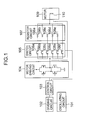
- an oscillating circuit 101 is connected to an input portion of a control circuit 103 via a dividing circuit 102.
- An output portion of the control circuit 103 is connected to a motor 109 for driving a time hand via a motor driving circuit 104, a switch circuit 105 and a resistor circuit 107.
- the motor 109 is a step motor having a constitution shown in Fig. 4.
- the motor driving circuit 104 is a well-known motor driving circuit having a constitution constituted by two pieces of P-channel MOS transistors and two pieces of N-channel MOS transistors and the coil of the motor is connected between common drains.
- the switch circuit 105 is provided with a plurality of the switches 106a through 106f connected in parallel and terminals of the respective switches 106a through 106f on one side are connected in parallel with one of the common drains of the motor driving circuit 104.
- the respective switches 106a through 106f are provided at inside of an integrated circuit (not illustrated) and are controlled to open and close by control by the control circuit 103.
- the respective switches 106a through 106e are for selecting resistors 108a through 108e used for setting a wave height value of a successive period of the drive pulse and the control circuit 103 is previously set with information of which of the switches 106a through 106e is controlled to an opened state or a closed state in accordance with a characteristic of the motor 109.
- the wave height value of the drive pulse in the successive period is set to a wave height value smaller than a predetermined wave height value in an initial period and sufficient for normally driving the motor 109.
- the switch 106f included in the switch circuit 105 is for generating a drive pulse having a predetermined wave height value during the initial period of the drive pulse.
- a wave height value of the drive pulse during the initial period is set to a wave height value larger than the predetermined wave height value in the successive period, further, sufficient for driving the motor 109.
- the resistor circuit 107 is provided with a plurality of the resistors 108a through 108e connected in parallel and terminals of the respective resistors 108a through 108e on one side are connected in series with terminals of the respectively corresponding switches 106 through 106e on other side at inside of the switch circuit 105. Other terminals of the respective resistors 108a through 108e are respectively connected in parallel with one terminal of the coil 110 for driving the motor 109.
- the respective resistors 108a through 108e are for setting the wave-height value of the successive period in the drive pulse and resistance values of the respective resistors 108a through 108e are selected to values different from each other. Since a necessary wave height value differs for the respective motor 109 used, there are previously prepared the plurality of resistors 108a through 108e having different resistance values, there are previously selected resistors used at a design stage or a fabrication stage in accordance with the characteristic of the motor 109 and in operating the electronic timepiece, as described later, the wave height value of the successive period becomes the predetermined value by using the previously selected resistors. Thereby, a circuit constitution can be made common even when the characteristic of the used motor 109 differs by a kind thereof. Further, the respective resistors 108a through 108e are provided at inside of the integrated circuit.
- the oscillating circuit 101, the dividing circuit 102, the control circuit 103, the motor driving circuit 104, the switch circuit 105 and the resistor circuit 107 constitute motor controlling means.
- the dividing circuit 102 divides the reference clock signal from the oscillating circuit 101 and outputs a time signal of a second signal or the like to the control circuit 103.
- the control circuit 103 outputs the time signal to the motor driving circuit 104.
- the motor driving circuit 104 outputs a drive pulse of a rectangular wave to the switch circuit 105.
- the motor driving circuit 104 is previously set to output a drive pulse of a rectangular wave having a predetermined wave height value higher than voltage necessary for normally driving the motor.
- control circuit 103 controls the switch circuit 105 in synchronism with supply of the time signal to the motor driving circuit 104, brings the switch 106f into a closed state during a previously set time period (initial period st) and thereafter controls to bring the switch 106f into an opened state again during the successive period.
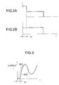
- the motor driving circuit 104 and the motor 109 are shortcircuited during the initial period and connected via the resistor 108a during the successive period. Therefore, as shown by Fig. 2A, the coil 110 of the motor 109 is supplied with a drive pulse having a predetermined wave height value larger than voltage necessary for driving the motor 109 during the initial period (st) and is supplied with a drive pulse of a wave height value smaller than the predetermined wave height value and capable of controlling to rotate the motor 109 in accordance with the characteristic of the motor 109.
- the analog electronic timepiece is particularly constituted such that in an analog electronic timepiece for controlling to rotate the motor 109 for driving a time hand by supplying a drive pulse from motor controlling means to the motor 109 and indicating time by the time hand driven to rotate by the motor 109 wherein the motor controlling means supplies a drive pulse having a predetermined wave height value to the motor 109 during an initial period of the drive pulse and supplies a drive pulse having a wave height value smaller than the predetermined wave height value and capable of controlling to rotate the motor to the motor 109 during a successive period successive to the initial period.
- the motor controlling means includes the resistors 108a through 108e connected in series with the motor 109 and the switch 106f connected in parallel with the resistors 108a through 108e, controls the switch 106f to a closed state during the initial period and controls the switch 106f to an opened state during the successive period.
- volumes of the saturated portions 403 and 404 of the stator 401 can be increased and therefore, mechanical strength of the stator 401 can be promoted and mass production performance of the electronic timepiece can be promoted.
- the saturated portions 403 and 404 can be saturated swiftly and therefore, the efficiency can be promoted and low power consumption can be achieved.
- the switch circuit 105 and the resistor circuit 107 are arranged in the integrated circuit and all the switches 106a through 106f included in the switch circuit 105 are controlled to open and close by the control circuit 103, the resistors 108a through 108e may be connected to a wiring pattern of a circuit board and any one of the resistors 108a through 108e used may previously be selected by cutting the wiring pattern in accordance with a kind of an electronic timepiece.
Landscapes
- Physics & Mathematics (AREA)
- General Physics & Mathematics (AREA)
- Electromechanical Clocks (AREA)
- Control Of Stepping Motors (AREA)
Abstract
Description
Claims (4)
- An analog electronic timepiece characterized in that in an analog electronic timepiece for controlling to rotate a motor for driving a time hand by supplying a drive pulse from motor controlling means to the motor and indicating time by the time hand driven to rotate by the motor:
wherein the motor controlling means supplies a drive pulse having a predetermined wave height value to the motor during an initial period of the drive pulse and supplies a drive pulse having a wave height value smaller than the predetermined wave height value and capable of controlling to rotate the motor to the motor during a successive period successive to the initial period. - The analog electronic timepiece according to Claim 1, wherein the motor controlling means includes resistors connected in series with the motor and switches connected in parallel with the resistors, controls the switches to a closed state during the initial period and controls the switches to an opened state during the successive period.
- The analog electronic timepiece according to Claim 1, wherein the motor controlling means is constituted to include a parallel circuit connected in parallel with a plurality of series circuits of the resistors and a first switch and include a second switch connected in parallel with the parallel circuit;
wherein during the initial period, the second switch is brought into a closed state and during the successive period, a specific one of the first switch previously selected in a plurality of the first switches is brought into a closed state and other of the first switches and the second switch are brought into an opened state. - The analog electric timepiece according to Claim 3, wherein the motor controlling means brings the specific one of the first switches into a normally closed state and brings the first switches other than the specific first switch to a normally opened state;
wherein the second switch is brought into a closed state during the initial period and the second switch is brought into an opened state during the successive period.
Applications Claiming Priority (2)
| Application Number | Priority Date | Filing Date | Title |
|---|---|---|---|
| JP2001151258A JP2002341065A (en) | 2001-05-21 | 2001-05-21 | Analog electronic clock |
| JP2001151258 | 2001-05-21 |
Publications (2)
| Publication Number | Publication Date |
|---|---|
| EP1260884A2 true EP1260884A2 (en) | 2002-11-27 |
| EP1260884A3 EP1260884A3 (en) | 2003-12-10 |
Family
ID=18996141
Family Applications (1)
| Application Number | Title | Priority Date | Filing Date |
|---|---|---|---|
| EP02253554A Withdrawn EP1260884A3 (en) | 2001-05-21 | 2002-05-21 | Analog electronic timepiece |
Country Status (4)
| Country | Link |
|---|---|
| US (1) | US20020172098A1 (en) |
| EP (1) | EP1260884A3 (en) |
| JP (1) | JP2002341065A (en) |
| CN (1) | CN1400510A (en) |
Families Citing this family (2)
| Publication number | Priority date | Publication date | Assignee | Title |
|---|---|---|---|---|
| JP2006226927A (en) * | 2005-02-21 | 2006-08-31 | Seiko Instruments Inc | Step motor driving device and analog electronic timepiece |
| JP5939852B2 (en) * | 2012-03-22 | 2016-06-22 | エスアイアイ・セミコンダクタ株式会社 | Analog electronic clock |
Family Cites Families (9)
| Publication number | Priority date | Publication date | Assignee | Title |
|---|---|---|---|---|
| DE2359142C2 (en) * | 1973-11-28 | 1982-04-22 | Vdo Adolf Schindling Ag, 6000 Frankfurt | Electric clock with stepper motor |
| DE2749141A1 (en) * | 1977-11-03 | 1979-05-10 | Quarz Zeit Ag | ELECTRIC CLOCK |
| DE2753732C2 (en) * | 1977-12-02 | 1986-04-24 | Kienzle Uhrenfabriken GmbH, 7730 Villingen-Schwenningen | Rotor control |
| JPS55160882A (en) * | 1979-06-01 | 1980-12-15 | Seiko Epson Corp | Hand type electronic wrist watch |
| JPS56164984A (en) * | 1980-05-23 | 1981-12-18 | Seiko Instr & Electronics Ltd | Electronic watch |
| JPS60204292A (en) * | 1984-03-27 | 1985-10-15 | Toshiba Corp | Drive device for motor |
| JPS6299733A (en) * | 1985-10-28 | 1987-05-09 | Fuji Photo Film Co Ltd | Shutter driving device |
| US4851755A (en) * | 1988-03-01 | 1989-07-25 | Ampex Corporation | Low power stepper motor drive system and method |
| US5059883A (en) * | 1989-06-29 | 1991-10-22 | Kabushiki Kaisha Toshiba | Method and apparatus for driving stepping motor |
-
2001
- 2001-05-21 JP JP2001151258A patent/JP2002341065A/en active Pending
-
2002
- 2002-05-08 US US10/140,719 patent/US20020172098A1/en not_active Abandoned
- 2002-05-21 CN CN02120448A patent/CN1400510A/en active Pending
- 2002-05-21 EP EP02253554A patent/EP1260884A3/en not_active Withdrawn
Also Published As
| Publication number | Publication date |
|---|---|
| JP2002341065A (en) | 2002-11-27 |
| CN1400510A (en) | 2003-03-05 |
| EP1260884A3 (en) | 2003-12-10 |
| US20020172098A1 (en) | 2002-11-21 |
Similar Documents
| Publication | Publication Date | Title |
|---|---|---|
| US8064294B2 (en) | Analogue electronic clock and motor control circuit | |
| JP2694010B2 (en) | Forward and reverse rotatable stepping motor and control method thereof | |
| US3893012A (en) | Stepping motor drive circuit | |
| US10637385B2 (en) | Stepping motor, motor drive device and time display device | |
| US4518900A (en) | Pulse motor driving apparatus | |
| US4115706A (en) | Integrated circuit having one-input terminal with selectively varying input levels | |
| US6680590B2 (en) | Vibration motor and apparatus using the same | |
| US20030227273A1 (en) | Apparatus and method for driving a stepping motor | |
| US20020172098A1 (en) | Analog electronic timepiece | |
| US4514676A (en) | Method and device for controlling a bidirectional stepping motor | |
| US4558268A (en) | Control device for two bidirectional step motors | |
| CA1193649A (en) | Method of, and apparatus for, damping of stepper motor using non-active windings | |
| GB1592898A (en) | Electronic timepieces having stepping motor-driven analogue time displays | |
| US4157647A (en) | Hand reversing system for an electronic timepiece | |
| US4491424A (en) | Electronic analog timepiece with rotation detection circuit | |
| JP4236956B2 (en) | Step motor control device and electronic timepiece | |
| EP0237778A2 (en) | Pulse motor and driving method thereof | |
| US4471284A (en) | Reversible stepping motor | |
| JP2852339B2 (en) | Step motor drive control device | |
| JPS6130225B2 (en) | ||
| JPH05207784A (en) | Reluctance type 3-phase high-speed motor | |
| JPH05341059A (en) | Step motor device for electronic watch/clock | |
| JP2004257751A (en) | Step motor control device and electronic timepiece | |
| RU1771056C (en) | Thyratron motor | |
| US20100002547A1 (en) | Watch fitted with an electric motor control case |
Legal Events
| Date | Code | Title | Description |
|---|---|---|---|
| PUAI | Public reference made under article 153(3) epc to a published international application that has entered the european phase |
Free format text: ORIGINAL CODE: 0009012 |
|
| AK | Designated contracting states |
Kind code of ref document: A2 Designated state(s): AT BE CH CY DE DK ES FI FR GB GR IE IT LI LU MC NL PT SE TR |
|
| AX | Request for extension of the european patent |
Free format text: AL;LT;LV;MK;RO;SI |
|
| PUAL | Search report despatched |
Free format text: ORIGINAL CODE: 0009013 |
|
| AK | Designated contracting states |
Kind code of ref document: A3 Designated state(s): AT BE CH CY DE DK ES FI FR GB GR IE IT LI LU MC NL PT SE TR |
|
| AX | Request for extension of the european patent |
Extension state: AL LT LV MK RO SI |
|
| 17P | Request for examination filed |
Effective date: 20040512 |
|
| AKX | Designation fees paid |
Designated state(s): CH DE LI |
|
| STAA | Information on the status of an ep patent application or granted ep patent |
Free format text: STATUS: THE APPLICATION IS DEEMED TO BE WITHDRAWN |
|
| 18D | Application deemed to be withdrawn |
Effective date: 20071201 |