EP1260836A1 - Color separating/synthesizing element and liquid crystal projector using it - Google Patents
Color separating/synthesizing element and liquid crystal projector using it Download PDFInfo
- Publication number
- EP1260836A1 EP1260836A1 EP01997710A EP01997710A EP1260836A1 EP 1260836 A1 EP1260836 A1 EP 1260836A1 EP 01997710 A EP01997710 A EP 01997710A EP 01997710 A EP01997710 A EP 01997710A EP 1260836 A1 EP1260836 A1 EP 1260836A1
- Authority
- EP
- European Patent Office
- Prior art keywords
- light
- output
- recombining
- light incidence
- incidence
- Prior art date
- Legal status (The legal status is an assumption and is not a legal conclusion. Google has not performed a legal analysis and makes no representation as to the accuracy of the status listed.)
- Granted
Links
Images




Classifications
-
- G—PHYSICS
- G02—OPTICS
- G02B—OPTICAL ELEMENTS, SYSTEMS OR APPARATUS
- G02B27/00—Optical systems or apparatus not provided for by any of the groups G02B1/00 - G02B26/00, G02B30/00
- G02B27/10—Beam splitting or combining systems
- G02B27/1006—Beam splitting or combining systems for splitting or combining different wavelengths
- G02B27/102—Beam splitting or combining systems for splitting or combining different wavelengths for generating a colour image from monochromatic image signal sources
- G02B27/1026—Beam splitting or combining systems for splitting or combining different wavelengths for generating a colour image from monochromatic image signal sources for use with reflective spatial light modulators
-
- G—PHYSICS
- G02—OPTICS
- G02B—OPTICAL ELEMENTS, SYSTEMS OR APPARATUS
- G02B27/00—Optical systems or apparatus not provided for by any of the groups G02B1/00 - G02B26/00, G02B30/00
- G02B27/10—Beam splitting or combining systems
- G02B27/14—Beam splitting or combining systems operating by reflection only
- G02B27/145—Beam splitting or combining systems operating by reflection only having sequential partially reflecting surfaces
-
- G—PHYSICS
- G02—OPTICS
- G02B—OPTICAL ELEMENTS, SYSTEMS OR APPARATUS
- G02B27/00—Optical systems or apparatus not provided for by any of the groups G02B1/00 - G02B26/00, G02B30/00
- G02B27/10—Beam splitting or combining systems
- G02B27/14—Beam splitting or combining systems operating by reflection only
- G02B27/149—Beam splitting or combining systems operating by reflection only using crossed beamsplitting surfaces, e.g. cross-dichroic cubes or X-cubes
-
- H—ELECTRICITY
- H04—ELECTRIC COMMUNICATION TECHNIQUE
- H04N—PICTORIAL COMMUNICATION, e.g. TELEVISION
- H04N9/00—Details of colour television systems
- H04N9/12—Picture reproducers
- H04N9/31—Projection devices for colour picture display, e.g. using electronic spatial light modulators [ESLM]
- H04N9/3102—Projection devices for colour picture display, e.g. using electronic spatial light modulators [ESLM] using two-dimensional electronic spatial light modulators
- H04N9/3105—Projection devices for colour picture display, e.g. using electronic spatial light modulators [ESLM] using two-dimensional electronic spatial light modulators for displaying all colours simultaneously, e.g. by using two or more electronic spatial light modulators
-
- H—ELECTRICITY
- H04—ELECTRIC COMMUNICATION TECHNIQUE
- H04N—PICTORIAL COMMUNICATION, e.g. TELEVISION
- H04N9/00—Details of colour television systems
- H04N9/12—Picture reproducers
- H04N9/31—Projection devices for colour picture display, e.g. using electronic spatial light modulators [ESLM]
- H04N9/3141—Constructional details thereof
- H04N9/315—Modulator illumination systems
- H04N9/3167—Modulator illumination systems for polarizing the light beam
-
- H—ELECTRICITY
- H04—ELECTRIC COMMUNICATION TECHNIQUE
- H04N—PICTORIAL COMMUNICATION, e.g. TELEVISION
- H04N5/00—Details of television systems
- H04N5/74—Projection arrangements for image reproduction, e.g. using eidophor
- H04N5/7416—Projection arrangements for image reproduction, e.g. using eidophor involving the use of a spatial light modulator, e.g. a light valve, controlled by a video signal
- H04N5/7441—Projection arrangements for image reproduction, e.g. using eidophor involving the use of a spatial light modulator, e.g. a light valve, controlled by a video signal the modulator being an array of liquid crystal cells
Definitions
- This invention relates to a color separating/recombining unit for LCD projector using three reflective LCD panels, and a compact LCD projector using this color separating/recombining unit.
- the conventional LCD projector using three LCD panels comprises a light source unit 1, a color separating/recombining unit 2, a reflective light modulating unit 3 consisting of three LCD panels 31, 32, 33 that modulate separated color components to convert into image lights of each color, and a projection optical system 4 including a projection lens.
- the light source unit 1 comprises a lamp 11a, a reflector 11b and polarization conversion means (not shown) that converts light from the lamp 11a into polarized light having a given polarization direction, so that the light source unit 1 may emit light polarized in a particular polarization direction.
- the color separating/recombining unit 2 is provided with two dichroic mirrors 21, 23 and one reflective mirror 22 to separate light incident from the light source unit 1 into three primary color components. In this projector, light emitted from the light source unit 1 is converted into s-polarized light by the polarization conversion means.
- s-polarized light of a red component reflects perpendicularly off a first dichroic mirror 21 and a blue component and a green component pass through the first dichroic mirror 21 and the separated red component enters a first polarizing beam splitter (hereafter referred to as PBS), namely a PBS for red 24.
- PBS first polarizing beam splitter
- the blue component passes through the second dichroic mirror 23, while the green component reflects off the second dichroic mirror 23.
- the s-polarized light of the blue component which passes through the second dichroic mirror 23, enters a second PBS, namely a PBS for blue 25, while the s-polarized light of the green component, which reflects perpendicularly off the second dichroic mirror 23, enters a third PBS, namely a PBS for green 26.
- the PBS for red 24 comprises a polarized light separating. surface 24a inside, which s-polarized light reflects perpendicularly and p-polarized light passes through. After being emitted from the first dichroic mirror 21, the red component reflects perpendicularly off the PBS for red 24 toward a first LCD panel 31. On the basis of image information for red, the LCD panel 31 rotates the polarization direction of the red light 90 degrees, which entered the part to be displayed in red, that is, the LCD panel 31 converts s-polarized red light into p-polarized red light and reflects it.. The p-polarized red image light, which is reflected by the LCD panel 31, passes through the PBS for red 24 and enters a dichroic prism for recombining 27.
- the PBS for blue 25 comprises a polarized light separating surface 25a inside, which s-polarized light reflects perpendicularly and p-polarized light passes through. After passing through the second dichroic mirror 23, s-polarized light of the blue component reflects perpendicularly off the PBS for blue 25 toward a second LCD panel 32. P-polarized blue image light, which is reflected by the LCD panel 32, passes through the PBS for blue 25 and enters the dichroic prism for recombining 27 from the opposite side where the red image light enters.
- the PBS for green 26 comprises a polarized light separating surface 26a inside, which s-polarized light reflects perpendicularly and p-polarized light passes through. After reflecting off the second dichroic mirror 23, s-polarized light of the green component reflects perpendicularly off the PBS for green 26 toward a third LCD panel 33. P-polarized green image light which is reflected by the LCD panel 33, passes through the PBS for green 26 and enters the dichroic prism for recombining 27 from a side orthogonal to sides where the red image light and the blue image light enter.
- the inside of the dichroic prism for recombining 27 comprises two dichroic surfaces 27a, 27b intersecting with each other at right angles.
- another conventional LCD projector using three LCD panels comprises a polarizing plate 12 transmitting only p-polarized light of white light emitted from a light source unit 1 provided with a light source 11 comprising a lamp 11a and a reflector 11b.
- a color separating/recombining unit 5 comprises a narrow-band retardation plate 51, which rotates a polarization direction 90 degrees, of p-polarized light having predetermined wavelength, for example only a red component, to convert into s-polarized light, a PBS for separating red 52, a PBS for red 53, two narrow-band retardation plates 54, 56, which rotate a polarization direction of only p-polarized light of the blue component by 90 degrees to convert into s-polarized light, a PBS for separating/recombining blue and green 55, and a PBS for recombining 57.
- the first narrow-band retardation plate 51 converts only red component into s-polarized light.
- the s-polarized light of the red component reflects perpendicularly off the PBS for separating red 52 and the PBS for red 53, and goes to LCD panel for red 31.
- P-polarized light of the blue component which passes through the PBS for separating red 52, is rotated its polarization direction 90 degrees to be converted into s-polarized light by the second narrow-band retardation plate 54.
- the s-polarized light of the blue component reflects perpendicularly off the PBS for separating/recombining blue and green 55 to enter LCD panel for blue 32.
- P-polarized light of the green component which passes through the PBS for separating red 52, passes through the second narrow-band retardation plate 54 and the PBS for separating/recombining blue and green 55 to enter LCD panel for green 33.
- These reflective LCD panels 31, 32, 33 rotate the polarization direction 90 degrees, of light which is incident to pixels to be displayed on the basis of image information on each color, and reflect the light in the opposite direction from which the light entered.
- Light, which is incident to pixels to be not displayed, is reflected by the LCD panels in the opposite direction from which the light entered without changing its polarization direction.
- the red image light reflected by the LCD panel for red 31 is p-polarized light
- the red image light passes though the PBS for red 53 and the PBS for recombining 57 to enter a projection optical system 4.
- the blue image light reflected by the LCD panel for blue 32 is p-polarized light
- the blue image light after passing through the PBS for separating/recombining blue and green 55 and being converted to s-polarized light by the third narrow-band retardation plate 56 again, the blue image light reflects perpendicularly off the PBS for recombining 57 to enter the projection optical system 4.
- the green image light reflected by the LCD panel for green 33 is s-polarized light, after reflecting perpendicularly off the PBS for separating/recombining blue and green 55 and passing through the third narrow-band retardation plate 56, the green image light reflects perpendicularly off the PBS for recombining 57 to enter the projection optical system 4.
- the PBS for red 24, the PBS for blue 25, the PBS for green 26 and the dichroic prism for recombining 27 are each formed in a cube.
- one side of each surface of these cubes should be longer than one side (or longer side) of each LCD panel 31, 32, 33.
- the two dichroic mirrors 21, 23 and the total reflective mirror 22 should be formed in rectangular so that the projected light in an incident direction and in a reflecting direction becomes a square bigger than an area of each LCD panel 31, 32, 33.
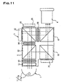
- the color separating/recombining unit 2 requires an area more than nine times larger than one of the PBS 24, 25, 26 or the dichroic prism 27, which is unfavorable in miniaturizing the color separating/recombining unit 2 and LCD projector using the unit. Also, since the path length for each color component between each LCD panels 31, 32, 33 and the projection optical system 4 is long, an aperture size of the projection optical system 4 should be big enough, which makes miniaturization of the LCD projector difficult.
- the color separating/recombining unit 5 would be smaller than that in Fig. 10 because four PBSs 52, 53, 55, 57 are arranged in two lines horizontally and vertically on a two-dimensional view.
- the present invention has an object to provide a remarkable miniature color separating/recombining means and a compact LCD projector.
- a color separating/recombining unit of the present invention is made to achieve the above mentioned object and characterized by being formed in a cube with a light incidence surface facing a light source unit which emits light having a predetermined polarization direction, three light incidence/output surfaces each facing reflective light modulating elements, a light output surface facing a projection optical system and another surface, and by comprising a color separating/recombining means inside.
- the color separating/recombining means separates light emitted from the light source unit into three primary color components and emits each separated color component from the corresponding light incidence/output surfaces.
- the color separating/recombining means After recombining lights of three primary color components reflected from a reflective light modulating element which is disposed opposite to each light incidence/output surface and rotates a polarization direction of the lights by 90 degrees, the color separating/recombining means emits the recombined color component toward a projection optical system.
- each of the light source unit, the projection optical system and a reflective light modulating element is placed opposed to each surface of the color separating/recombining unit. It never happen to align the light source unit and one reflective modulating element (LCD panel), one reflective light modulating element (LCD panel) and the projection optical system, or two reflective light modulating elements (LCD panels) side by side, thereby miniaturizing the color separating/recombining unit to one-fourth as compared to the conventional one in Fig. 11.
- an optical path between the light source unit and each reflective light modulating element (LCD panel) through the color separating/recombining unit and an optical path between each reflective light modulating element (LCD panel) and the projection optical system through the color separating/recombining unit can be shorten, therefore reducing diffusion of light. This also reduces power output of the light source unit and makes the light source unit and the projection optical system small, thereby obtaining further miniaturized LCD projector as a whole.
- the LCD projector of the present invention is so structured that five surfaces out of six surfaces of the cube respectively faces a light source unit, one of three reflective light modulating elements (LCD panels) or a projection optical system.
- the position of the light incidence surface, the light incidence/output surfaces, the light output surface is not limited.
- the light incidence surface for example, may be arranged at the back of the light output surface in the cube and the light incidence/output surfaces may be arranged on three surfaces out of four surfaces orthogonal to both the light incidence surface and the light output surface.
- the light incidence surface and the light output surface are orthogonal to each other, the first light incidence/output surface is arranged at the back of the light incidence surface, the second light incidence/output surface is arranged at the back of the light output surface, and the third light incidence/output surface is orthogonal to the first, second light incidence/output surfaces, the light incidence surface and the light output surface.
- the color separating/recombining means can be simplified down to one comprising just three optical surfaces.
- the color separating/recombining means may comprise a first optical surface inclined at a 45-degree angle to the light incidence surface and the light output surface, a second optical surface inclined at a 45-degree angle to the first and third light incidence/output surfaces, and a third optical surface inclined at a 45-degree angle to the third light incidence/output surface and the light output surface.
- each optical surface may be so designed that, on the basis of the polarization direction of three primary color components, the optical surfaces separate light incident from the light incidence surface into three color components, emit the color components in three directions orthogonal to each other, recombine the color components incident from the opposite direction, and emit the recombined color components from the light output surface.
- the color separating/recombining means is structured, for example, so that the first optical surface transmits both s-polarized light and p-polarized light of a first component, and reflects s-polarized light of a second and third components while transmitting p-polarized light.
- the second and third optical surfaces reflect s-polarized light of the first component while transmitting p-polarized light, and transmit both polarized lights of the second and third components.
- the LCD projector in this invention comprises above mentioned color separating/recombining unit, a light source unit disposed on the light incidence surface side of the color separating/recombining unit and emitting light having predetermined polarization direction, a first, second and third reflective light modulating elements each disposed on the light incidence/output surface side of the color separating/recombining unit, a projection optical system disposed on the light output surface side of the color separating/recombining unit.
- the light source unit comprises a white light source, a polarization conversion means for converting light from the white light source into light having a predetermined polarization direction, and means for rotating a polarization direction of light having a particular wavelength by 90 degrees.
- the LCD projector using three LCD panels can be made remarkably small as compared to the conventional projector.
- the method of fabricating the color separating/recombining unit in a cube which has three optical surfaces inside, is not particularly limited, one example can be adopted.
- the method includes; dividing the color separating/recombining unit into six tetrahedrons; forming optical surfaces having a predetermined property on one divided surface or both divided surfaces facing each other by, for example, a well-known method for forming thin film; and joining the tetrahedrons to be a cube.
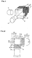
- a LCD projector shown in a perspective view of Fig. 1 comprises a light source unit 10, a color separating/recombining unit 20 characterizing an embodiment of this invention, a color component modulation unit 30 including three reflective LCD panels 31, 32, 33, and a projection optical system 40.
- Light which is emitted from the light source unit 10 and has a predetermined polarization direction, enters a light incidence surface 21 being one of surfaces of the color separating/recombining unit 20 and is separated into three primary color components - in this embodiment, a blue component as a first color component, a green component as a second color component and a red component as a third color component - by a color separating/recombining means 50 in the color separating/recombining unit 20.
- the three color components are recombined after modulated by the color component modulation unit 30.
- the recombined color component is emitted from a light output surface 22 orthogonal to the light incidence surface 21 and projected and magnified by the projection optical system 40.
- the light source unit 10 comprises a lamp 11, a reflector 12 which reflects light from the lamp 11 toward the light incidence surface 21, a polarizer 13 and a narrow-band retardation plate 14 which arrange the light heading for the light incidence surface 21 to have a predetermined polarization direction.
- the polarizer 13 transmits only light having a polarization direction (horizontal direction), which is indicated by arrowheads with an inclined solid line in a perspective view of Fig. 4.
- a polarization direction of one color component - for example, green component - of the light passed through the polarizing plate 13 is rotated 90 degrees by the narrow-band retardation plate 14 to have a polarization direction (vertical direction) as indicated by arrowheads with a vertical solid line in a perspective view of Fig. 4.
- a combination of a dichroic mirror and a retardation plate can be used to obtain equivalent effect.
- p-polarized light is light vibrating in a plane including incident light, transmissive light and reflected light
- s-polarized light is light vibrating perpendicular to the plane, which defined by a direction of incident light and a reflecting surface. Therefore, the vibrating direction of the incident light determines whether the light is p-polarized light or s-polarized light based on the incident and emitting direction of light and the reflecting surface.
- light even which enters from same direction and vibrates in a same direction, varies between p-polarized light and s-polarized light according to three optical surfaces of the color separating/recombining means 50.
- the polarization plane of the polarized light is expressed in an xyz-space. If red light, for example, vibrates in a plane-xy, the red light is referred to as Rxy.
- a polarization direction indicated by arrowheads with an inclined solid line shows that a plane-yz is a polarization plane of the polarized light.
- a polarization direction indicated by arrowheads with a vertical solid line shows that a plane-xy is a polarization plane of the polarized light.
- the plane-yz is p-polarized light
- the plane-xy is s-polarized light.
- the light output surface 22 facing the projection optical system 40 may be placed at the back of the light incidence surface 21, that is, parallel to the light incidence surface 21, the light output surface 22 in this embodiment is placed on a front surface orthogonal to the light incidence surface 21 of the color separating/recombining means, in order to simplify an internal constitution of the color separating/recombining unit 20 as well as to miniaturize the unit 20.
- the three surfaces out of the remaining four surfaces of the color separating/recombining unit 20 are used as a first light incidence/output surface 23 corresponding to a first color component, a second light incidence/output surface 24 corresponding to a second color component, and third light incidence/output surface 25 corresponding to a third color component, which respectively faces LCD panels 31, 32, 33 comprising the reflective light modulating element.
- the position between these three light incidence/output surfaces, the light incidence surface 21 and the light output surface 22 can be designed freely in consideration of the polarization direction of three color components and the position of the light incidence surface 21 and the light output surface 22.
- the first light incidence/output surface23 is placed on a left side surface opposite to the light incidence surface 21 placed on a right side surface of the color separating/recombining unit 20.
- the second light incidence/output surface 24 is placed at the back side surface opposite to the light output surface 22 placed on a front surface of the color separating/recombining unit 20.
- the third light incidence/output surface 25 is placed on an upper surface of the color separating/recombining unit 20, orthogonal to the light incidence surface 21, the light output surface 22, the first and second light modulating surfaces 23, 24.
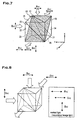
- the color separating/recombining means 50 has three optical surfaces; a first optical surface 51, a second optical surface 52, and a third optical surface 53.
- the first optical surface 51 as emphasized by upper right diagonal stripes in the perspective view of Fig. 5, is placed at a 45-degree angle with respect to the light incidence surface 21 and the light output surface 22 and orthogonal to the third light incidence/output surface 25 and a bottom surface 26.
- the optical surface 51 in combination with the light incidence surface 21 and the first light incidence/output surface23 is viewed from above in two-dimensional view, they would look like a letter Z.
- the second optical surface 52 is placed at a 45-degree angle with respect to the first light incidence/output surface 23 and the third light incidence/output surface 25 and orthogonal to the second light incidence/output surface 24 and the light output surface 22.
- the second optical surface 52 in combination with the third light incidence/output surface 25 and the bottom surface 26 is viewed from the side of the second light incidence/output surface 24 (from back side), they would look like a letter Z.
- the third optical surface 53 is placed at a 45-degree angle with respect to the third light incidence/output surface 25 and the light output surface 22 and orthogonal to the light incidence surface 21 and the first light incidence/output surface 23.
- the third optical surface 53 in combination with the third light incidence/output surface 25 and the bottom surface 26 is viewed from the side of the light incidence surface 21, they would look like a letter Z.
- the first optical surface 51 has a property of functioning as a polarized light separating surface which selectively separates only the polarized light with a particular wavelength as shown in a table 1. Specifically speaking, the first optical surface 51 reflects s-polarized light of the blue component as a first color component (referred to as "B” in tables below) and s-polarized light of the green component as a second color component (referred to as "G” in tables below), and transmits p-polarized light of the blue component as a first color component, p-polarized light of the green component as a second color component and s- and p-polarized light of the red component as a third color component (referred to as "R" in tables below).
- B first color component
- G second color component
- the second optical surface 52 has a property of functioning as a polarized light separating surface which selectively separates only the polarized light with a particular wavelength as shown in table 2. Specifically speaking, the second optical surface 52 reflects only s-polarized light of the red component and transmits p-polarized light of the red component, p- and s-polarized light of the green component and p- and s-polarized light of the blue component.
- the third optical surface 53 has a property of functioning as a polarized light separating surface which selectively separates only the polarized light with a particular wavelength as shown in table 3. Specifically speaking, the third optical surface 53 reflects only s-polarized light of the red component and transmits p-polarized light of the red component, p- and s-polarized light of the green component and p- and s-polarized light of the blue component.
- the properties of the second optical surface 52 and the third optical surface 53 are same as apparent from the tables 2 and 3. Hence, it is enough for the color separating/recombining means 50 to include one surface having same property as the first optical surface 51 and two surfaces having same property as the second optical surface 52 or the third optical surface 53.
- a blue component Byz incident from the light incidence surface 21, whose polarization plane is the plane-yz, is p-polarized light with respect to the first optical surface 51, thereby passing through the first optical surface 51 as the blue component Byz.
- the blue component Byz is s-polarized light with respect to the second optical surface 52
- the blue component Byz can pass through the second optical surface 52 since the second optical surface 52 has the property of transmitting s-polarized light.
- the blue component Byz can be emitted from the first light incidence/output surface 23 as the blue component Byz without obstruction by either of the first or second optical surface 51, 52.
- the green component Gxy incident from the light incidence surface 21, whose polarization plane is the plane-xy, is s-polarized light with respect to the first optical surface 51
- the green component Gxy reflects by 90 degrees off the first optical surface 51 and emitted from the second light incidence/output surface 24 as the green component Gxz whose polarization plane is the plane-xz.
- the red component Ryz incident from the light incidence surface 21, whose polarization plane is the plane-yz, is p-polarized light with respect to the first optical surface 51, as shown in Figs. 4, 5 and 6, and passes through the first optical surface 51 as the red component Ryz. Since the red component Ryz is s-polarized light with respect to the second optical surface 52, the red component Byz reflects upward by 90 degrees off the second optical surface 52 because the surface 52 has the property of reflecting the s-polarized light of red component. Then the red component Ryz is emitted from the third light incidence/output surface 25 as a red component Rxz whose polarization plane is the plane-xz.
- the LCD panels 31, 32, 33 respectively reflect light, which entered pixels to be displayed, in the opposite direction to the incident direction by rotating the polarization direction of light by 90 degrees. Also, the LCD panels 31, 32, 33 reflect light, which entered other pixels not to be displayed, in opposite direction to the incident direction without rotating the polarization direction of the light.
- the blue component Byz emitted from the first light incidence/output surface 23 is modulated in the first LCD panel for blue 31 and enters the first light incidence/output surface 23 as blue image light converted into a blue component Bxy whose polarization plane is the plane-xy.
- the blue component blue component Bxy incident from the first light incidence/output surface 23 is s-polarized light with respect to the first optical surface 51, reflects by 90 degrees off the first optical surface 51 and is emitted from the light output surface 22 as a blue component Bxz whose polarization plane is the plane-xz. Since the second and third optical surfaces 52 and 53 have the property of transmitting s-polarized light and p-polarized light of the blue component, the blue component Bxz can be emitted from the light output surface 22 without obstruction by either of the optical surface 52 or 53.
- the green component Gxz emitted from the second light incidence/output surface 24 is modulated in the second LCD panel for green 32 and enters the second light incidence/output surface 24 as green image light converted into a green component Gyz whose polarization plane is the plane-yz.
- the green component Gyz incident from the light incidence/output surface 24 is p-polarized light with respect to the first optical surface 51, as shown in Figs. 5, 7, and 8, and is emitted from the light output surface 22 through the first optical surface 51. Since the second and third optical surface 52, 53 have the property of transmitting s-polarized light and the p-polarized light of the green component, the green component Gyz can be emitted from the light output surface 22 without obstruction by either of the optical surface 52 or 53.
- the red component Rxz emitted from the third light incidence/output surface 25 is modulated in the third LCD panel for red 33 and enters the third light incidence/output surface 25 as red image light converted into a red component Rxy whose polarization plane is the plane-xy.
- the red component Rxy incident from the light incidence/output surface 25 is p-polarized light with respect to the second optical surface 52, as shown in Figs. 6, 7, and 8, and passes through the second optical surface 52.
- the red component Rxy is s-polarized light with respect to the third optical surface 53, is reflected forward on the third optical surface 53 and is emitted from the light output surface 22 as a red component Ryz. Since the first optical surface 51 has the property of transmitting s-polarized light and p-polarized light of the red component, the red component Ryz can be emitted from the light output surface 22 without obstruction by the first optical surface 51.
- the first optical surface 51 has functions of separating the green component of the second color component from light emitted from the light source unit 10 and recombining the blue image light of the first color component reflected from the first LCD panel 31 and the green image light of the second color component incident from the second LCD panel 32.
- the second optical surface 52 has functions of separating the red component of the third color component from light incident from the light source unit 10.
- the third optical surface 53 has functions of recombining the recombined blue and green image lights as the first and second color components and the red image light of the third color component incident from the third LCD panel 33.
- a cube of the color separating/recombining unit 20 is divided at optical surfaces 51, 52, and 53 into six tetrahedrons 20a-20f.
- optical areas 51a-53a are formed at one side (or both sides) of the joint surfaces 51a-53a and 51b-53b, which are facing each other, of the tetrahedrons 20a-20f.
- the joint surfaces 51a-53a opposed to the joint surfaces 51b-53b of tetrahedrons 20a-20f are jointed each other by bonding or fusion.
- the color separating/recombining unit 20 can be fabricated readily with high-accuracy.
- the reference numbers 21a and 21b, 22a and 22b, 23a and 23b, 24a and 24b, 25a and 25b and 26a and 26b respectively represent the divided light incidence surfaces, the divided light output surfaces, the divided first light incidence/output surfaces, the divided second light incident/output surfaces, the divided third light incidence/output surfaces and the divided another surfaces (bottom surfaces).
- a first tetrahedron 20a consists of a light output surface 22a and a first light incidence/output surface 23b in the form of an isosceles right-angled triangle and an optical surface 53a and a joint surface 52b in the form of a right-angled triangle.
- a second tetrahedron 20b consists of a light output surface 22b and a third light incidence/output surface 25b in the form of an isosceles right-angled triangle and an optical surface 52a and a joint surface 51b in the form of a right-angled triangle.
- a third tetrahedron 20c consists of a light incidence surface 21a and a third light incidence/output surface 25b in the form of an isosceles right-angled triangle and an optical surface 51a and a joint surface 53b in the form of a right-angled triangle.
- a fourth tetrahedron 20d consists of a first light incidence/output surface 23a and another surface 26a in the form of an isosceles right-angled triangle and an optical surface 51a and a joint surface 53b in the form of a right-angled triangle.
- a fifth tetrahedron 20e consists of a second light incidence/output surface 24b and another surface 26b in the form of an isosceles right-angled triangle and an optical surface 52a and a joint surface 51b in the form of a right-angled triangle.
- a sixth tetrahedron 20f consists of a light incidence surface 21b and a second light incidence/output surface 24a in the form of an isosceles right-angled triangle and an optical surface 53a and a joint surface 52b in the form of a right-angled triangle.
- the LCD projector in this embodiment when necessary, may comprise a narrow-band retardation plate 41 which converts p-polarized light of the green component to s-polarized light of the green component by rotating its polarization direction 90 degrees, and a polarizing plate 42 which transmits s-polarized light of each color component in order to improve contrast of the recombined image light before it enters the projection lens system 43 to be magnified and projected.
- a narrow-band retardation plate 41 which converts p-polarized light of the green component to s-polarized light of the green component by rotating its polarization direction 90 degrees
- a polarizing plate 42 which transmits s-polarized light of each color component in order to improve contrast of the recombined image light before it enters the projection lens system 43 to be magnified and projected.
- the color separating/recombining unit 20 in this embodiment is formed in a cube and comprises a light incidence surface 21 facing the light source unit 10 which emits light having a predetermined polarization direction, three light incidence/output surfaces 23, 24, 25 respectively facing the LCD panels 31, 32, 33, a light output surface 22 facing the projection optical system 40, and another surface 26.
- the color separating/recombining unit 20 also comprises a color separating/recombining means 50 inside.
- the color separating/recombining means 50 separates light emitted from the light source unit 10 into three primary color components and emits the separated color components respectively from the corresponding light incidence/output surfaces 23, 24, 25.
- the color separating/recombining means 50 recombines the three primary color components to emit from the light output surface 22 toward the projection optical system 40.
- each surface of the color separating/recombining unit 20 can be shorten to a length as same as one side of the LCD panels 31, 32, 33 (if the LCD panels 31, 32, 33 are rectangular, a longer side of it). Therefore, the LCD projector using three LCD panels can carry out separation and recombination of color components in one- ninth of the area of the conventional projector in Fig. 10 as well as one-fourth of the area of the conventional projector in Fig. 11. In short, a remarkably compact color separating/recombining unit 20 can be obtained as compared to conventional color separating/recombining unit, resulting in a remarkably compact LCD projector using the unit 20.
- the path length for each color component between the light source unit 10 and the projection optical system 40 can be shorten to approximately one-third as compared to a conventional one, thereby decreasing loss of light. This allows the light source unit 10 to reduce its power output, cost and size. Hence, the further miniaturized LCD projector can be provided at a low cost.
- the path length for each color component between each LCD panel 31, 32, 33 and the projection optical system 40 can be shorten to approximately a half as compared to a conventional one, a diffusion of each color component can be decreased, thereby miniaturizing the projection optical system 40.
- the further miniaturized LCD projector can be provided.
- the color separating/recombining unit in this invention is formed in a cube and comprises a light incidence surface facing a light source unit which emits light having a predetermined polarization direction, three light incidence/output surfaces each facing reflective light modulating elements, a light output surface facing a projection optical system, and another surface.
- the color separating/recombining unit also comprises a color separating/recombining means inside.
- the color separating/recombining means separates light emitted from the light source unit into three primary color components and emits the separated color components respectively from the corresponding light incidence/output surface.
- the color separating/recombining means recombines the three primary color components to emit from the light output surface toward the projection optical system.
- a remarkably compact color separating/recombining unit can be obtained as compared to conventional color separating/recombining units, thereby obtaining a remarkably compact LCD projector with three LCD panels as compared to the conventional LCD projector with three LCD panels by using the color separating/recombining unit.
- the path length for each color component between the light source unit and the projection optical system can be shorten to approximately one-third as compared to a conventional one, thereby decreasing loss of light. This allows the light source unit to reduce its power output, cost and size. Hence, the further miniaturized LCD projector can be provided at a low cost as well as reduce power consumption.
- the path length for each color component between the LCD panel and the projection optical system can be shorten to approximately one-third as compared to a conventional one, a diffusion of each color component, which occurs between the LCD panels and the projection optical system, can be decreased, resulting in miniaturization of the projection optical system.
- the further miniaturized LCD projector can be provided.
- a small number of parts help sharply cut costs for assembling the LCD projector.
- the color separating/recombining unit according to the present invention is used for LCD projector using three reflective LCD panels, and especially is suitable for miniaturization of the LCD projector.
Landscapes
- Physics & Mathematics (AREA)
- General Physics & Mathematics (AREA)
- Optics & Photonics (AREA)
- Engineering & Computer Science (AREA)
- Multimedia (AREA)
- Signal Processing (AREA)
- Projection Apparatus (AREA)
- Liquid Crystal (AREA)
- Optical Elements Other Than Lenses (AREA)
- Polarising Elements (AREA)
Abstract
Description
| property of first optical surface | ||
| color component | s-polarized light | p-polarized light |
| B | reflected | transmittable |
| G | reflected | transmittable |
| R | transmittable | transmittable |
| property of second optical surface | ||
| color component | s-polarized light | p-polarized light |
| B | transmittable | transmittable |
| G | transmittable | transmittable |
| R | reflected | transmittable |
| property of third optical surface | ||
| color component | s-polarized light | p-polarized light |
| B | transmittable | transmittable |
| G | transmittable | transmittable |
| R | reflected | transmittable |
Claims (7)
- A color separating/recombining unit which is formed in a cube and comprises:a light incidence surface facing a light source unit which emits light having a predetermined polarization direction;three light incidence/output surfaces each facing reflective light modulating elements;a light output surface facing a projection optical system;another surface; anda color separating/recombining means inside whereinthe color separating/recombining means separates light emitted from the light source unit into three primary color components, emits the separated components from the light incidence/output surfaces, recombines the three color components which are rotated their polarization directions by 90 degrees and reflected by the reflective light modulating elements placed opposite to light incidence/output surfaces, and emits the recombined color component toward the projection optical system.
- The color separating/recombining unit according to claim 1, wherein
the light incidence surface and the light output surface are orthogonal to each other;
a first light incidence/output surface is positioned at the back of the light incidence surface;
a second light incidence/output surface is positioned at the back of the light output surface; and
a third light incidence/output surface is orthogonal to the first and second incident/output surfaces. - The color separating/recombining unit according to claim 1, wherein
the color separating/recombining means comprises a first optical surface inclined at a 45-degree angle to the light incidence surface and the light output surface, a second optical surface inclined at a 45-degree angle to the first and third light incidence/output surfaces, and a third optical surface inclined at a 45-degree angle to the third light incidence/output surface and the light output surface. - LCD projector comprising:a color separating/recombining unit which is formed in a cube and comprises a light incidence surface facing a light source unit which emits light having a predetermined polarization direction, three light incidence/output surfaces each facing reflective light modulating elements, a light output surface facing a projection optical system, another surface, and a color separating/recombining means inside, wherein the color separating/ recombining means separates light emitted from the light source unit into three primary color components, emits the separated components from the corresponding light incidence/output surfaces, recombines the three color components which are rotated their polarization directions by 90 degrees and reflected by the reflective light modulating elements placed opposite to light incidence/output surfaces, and emits the recombined color component toward the projection optical system;a light source unit arranged on a light incidence surface side of the color separating/recombining unit and emitting light having a predetermined polarization direction;first, second, and third reflective light modulating elements respectively arranged on light incidence/output surface sides of the color separating/recombining unit; anda projection optical system arranged on a light output surface side of the color separating/recombining unit.
- The LCD projector according to claim 4, wherein
the light incidence surface and the light output surface are orthogonal to each other,
the first light incidence/output surface is positioned at the back of the light incidence surface,
the second light incidence/output surface is positioned at the back of the light output surface,
the third light incidence/output surface is orthogonal to the first and second incidence/output surfaces. - The LCD projector according to claim 4, wherein
the color separating/recombining means comprises a first optical surface inclined at a 45-degree angle to the light incidence surface and the light output surface, a second optical surface inclined at a 45-degree angle to the first and third light incidence/output surfaces, and a third optical surface inclined at a 45-degree angle to the third light incidence/output surface and the light output surface. - The LCD projector according to claims 4 to 6, wherein
the light source unit comprises a white light source, a polarization conversion means for arranging light from the white light source to have a predetermined polarization direction, and means for rotating a polarization direction of light having a particular wavelength by 90 degrees.
Applications Claiming Priority (3)
| Application Number | Priority Date | Filing Date | Title |
|---|---|---|---|
| JP2000359978 | 2000-11-27 | ||
| JP2000359978A JP3609715B2 (en) | 2000-11-27 | 2000-11-27 | Color separation / synthesis device and liquid crystal projector using the same |
| PCT/JP2001/010296 WO2002042807A1 (en) | 2000-11-27 | 2001-11-26 | Color separating/synthesizing element and liquid crystal projector using it |
Publications (3)
| Publication Number | Publication Date |
|---|---|
| EP1260836A1 true EP1260836A1 (en) | 2002-11-27 |
| EP1260836A4 EP1260836A4 (en) | 2006-01-25 |
| EP1260836B1 EP1260836B1 (en) | 2008-03-05 |
Family
ID=18831648
Family Applications (1)
| Application Number | Title | Priority Date | Filing Date |
|---|---|---|---|
| EP01997710A Expired - Lifetime EP1260836B1 (en) | 2000-11-27 | 2001-11-26 | Color separating/synthesizing element and liquid crystal projector using it |
Country Status (5)
| Country | Link |
|---|---|
| US (1) | US6840626B2 (en) |
| EP (1) | EP1260836B1 (en) |
| JP (1) | JP3609715B2 (en) |
| DE (1) | DE60133091T2 (en) |
| WO (1) | WO2002042807A1 (en) |
Cited By (3)
| Publication number | Priority date | Publication date | Assignee | Title |
|---|---|---|---|---|
| DE10359992A1 (en) * | 2003-12-19 | 2005-07-14 | Carl Zeiss Jena Gmbh | Multicolor image projection apparatus, has color management system arranged between light source and light modulators and color management system arranged after light modulators |
| EP1796399A3 (en) * | 2005-12-09 | 2008-11-26 | Canon Kabushiki Kaisha | Wavelength-selective polarization conversion element, illumination optical system, projection display optical system, and image projection apparatus |
| EP2418522A1 (en) * | 2004-07-06 | 2012-02-15 | RealD Inc. | Illumination systems |
Families Citing this family (14)
| Publication number | Priority date | Publication date | Assignee | Title |
|---|---|---|---|---|
| JP3976720B2 (en) | 2003-02-25 | 2007-09-19 | 三洋電機株式会社 | Image light generating device and projection image display device |
| CN100489573C (en) | 2003-03-27 | 2009-05-20 | 三洋电机株式会社 | Color separating and composing element, graph light producing device, and projection type graph display |
| US20050243283A1 (en) * | 2004-04-28 | 2005-11-03 | Ching-Fuh Lin | Reflective type beam splitting and combining device |
| JP2006343632A (en) * | 2005-06-10 | 2006-12-21 | Pentax Corp | Optical system for oblique projection projector |
| JP4716823B2 (en) * | 2005-08-31 | 2011-07-06 | 三洋電機株式会社 | Optical element, illumination device, and projection-type image display device |
| US8267521B2 (en) | 2005-08-31 | 2012-09-18 | Sanyo Electric Co., Ltd. | Optical element, illuminating device, and projection type video display |
| US7445341B2 (en) * | 2005-09-21 | 2008-11-04 | 3M Innovative Properties Company | Four panel liquid crystal display system |
| JP2007157638A (en) * | 2005-12-08 | 2007-06-21 | Minebea Co Ltd | Light source device and image display device using the same |
| JP4795078B2 (en) * | 2006-04-03 | 2011-10-19 | キヤノン株式会社 | Image forming optical system, image projecting optical system, and image projecting apparatus |
| JP5043520B2 (en) | 2006-06-16 | 2012-10-10 | キヤノン株式会社 | Optical element, image projection optical system, and image projection apparatus |
| US11378810B2 (en) * | 2018-03-20 | 2022-07-05 | Arizona Board Of Regents On Behalf Of The University Of Arizona | Polygon x-prism for imaging and display applications |
| CN110191327B (en) * | 2019-06-05 | 2022-02-15 | 南华智能精密机器(深圳)有限公司 | Two-piece type LCD projector |
| US11867920B2 (en) * | 2021-01-08 | 2024-01-09 | Sintai Optical (Shenzhen) Co., Ltd. | Beam splitting and combining device and electronic device |
| CN116300043A (en) * | 2023-03-22 | 2023-06-23 | 上海电镜医疗科技有限公司 | A multi-band illumination source and endoscope system |
Family Cites Families (15)
| Publication number | Priority date | Publication date | Assignee | Title |
|---|---|---|---|---|
| JP2849238B2 (en) | 1991-07-19 | 1999-01-20 | 三菱電機株式会社 | Single polarization wave conversion device and liquid crystal video projector device |
| US6183091B1 (en) * | 1995-04-07 | 2001-02-06 | Colorlink, Inc. | Color imaging systems and methods |
| US5605390A (en) * | 1996-01-25 | 1997-02-25 | Sarif, Inc. | Optical projector |
| JP3941123B2 (en) | 1996-08-20 | 2007-07-04 | セイコーエプソン株式会社 | Polarized illumination device and projection display device |
| JPH10260313A (en) | 1997-03-19 | 1998-09-29 | Fujitsu General Ltd | Light source device for reflective polarization modulator |
| US6486997B1 (en) * | 1997-10-28 | 2002-11-26 | 3M Innovative Properties Company | Reflective LCD projection system using wide-angle Cartesian polarizing beam splitter |
| JP3661392B2 (en) | 1998-02-18 | 2005-06-15 | セイコーエプソン株式会社 | Polarized illumination device and projection display device |
| TW407222B (en) * | 1998-05-14 | 2000-10-01 | Primax Electronics Ltd | The projective display apparatus used to show the image |
| US6113239A (en) * | 1998-09-04 | 2000-09-05 | Sharp Laboratories Of America, Inc. | Projection display system for reflective light valves |
| US6273567B1 (en) * | 1998-09-14 | 2001-08-14 | Arlie R. Conner | Compact multi-path LCD projector |
| JP3370010B2 (en) * | 1999-03-31 | 2003-01-27 | 三洋電機株式会社 | LCD projector |
| US6327093B1 (en) * | 1999-06-04 | 2001-12-04 | Sharp Kabushiki Kaisha | Image display apparatus |
| US6565211B1 (en) * | 1999-10-22 | 2003-05-20 | Nikon Corporation | Projection type display device |
| JP3918416B2 (en) | 2000-01-28 | 2007-05-23 | セイコーエプソン株式会社 | Projection display |
| KR100381051B1 (en) * | 2000-12-02 | 2003-04-18 | 엘지전자 주식회사 | Optical System Of Liquid Crystal Projector |
-
2000
- 2000-11-27 JP JP2000359978A patent/JP3609715B2/en not_active Expired - Fee Related
-
2001
- 2001-11-26 WO PCT/JP2001/010296 patent/WO2002042807A1/en not_active Ceased
- 2001-11-26 US US10/181,936 patent/US6840626B2/en not_active Expired - Fee Related
- 2001-11-26 DE DE60133091T patent/DE60133091T2/en not_active Expired - Fee Related
- 2001-11-26 EP EP01997710A patent/EP1260836B1/en not_active Expired - Lifetime
Cited By (4)
| Publication number | Priority date | Publication date | Assignee | Title |
|---|---|---|---|---|
| DE10359992A1 (en) * | 2003-12-19 | 2005-07-14 | Carl Zeiss Jena Gmbh | Multicolor image projection apparatus, has color management system arranged between light source and light modulators and color management system arranged after light modulators |
| EP2418522A1 (en) * | 2004-07-06 | 2012-02-15 | RealD Inc. | Illumination systems |
| EP1796399A3 (en) * | 2005-12-09 | 2008-11-26 | Canon Kabushiki Kaisha | Wavelength-selective polarization conversion element, illumination optical system, projection display optical system, and image projection apparatus |
| US7631972B2 (en) | 2005-12-09 | 2009-12-15 | Canon Kabushiki Kaisha | Wavelength-selective polarization conversion element, illumination optical system, projection display optical system, and image projection apparatus |
Also Published As
| Publication number | Publication date |
|---|---|
| JP3609715B2 (en) | 2005-01-12 |
| US20030011752A1 (en) | 2003-01-16 |
| WO2002042807A1 (en) | 2002-05-30 |
| US6840626B2 (en) | 2005-01-11 |
| DE60133091T2 (en) | 2008-07-03 |
| EP1260836A4 (en) | 2006-01-25 |
| EP1260836B1 (en) | 2008-03-05 |
| DE60133091D1 (en) | 2008-04-17 |
| JP2002162520A (en) | 2002-06-07 |
Similar Documents
| Publication | Publication Date | Title |
|---|---|---|
| US6840626B2 (en) | Color separating/synthesizing element and liquid crystal projector using it | |
| US6229646B1 (en) | Plate-like polarizing element, a polarizing conversion unit provided with the element, and a projector provided with the unit | |
| EP0443586B1 (en) | Projector | |
| US6419362B1 (en) | Liquid crystal projection apparatus | |
| CN100361021C (en) | Illumination optical system, image display device, and method for illuminating space conditioner | |
| US6019474A (en) | Modified X-cube arrangement for improved contrast projection display | |
| JPH11183848A (en) | Polarized illumination device and projection display device | |
| EP0984637A2 (en) | Projection display system for reflective light valves | |
| US6229581B1 (en) | Projection type picture display apparatus | |
| JP2002182307A (en) | Projection display device | |
| JP4520943B2 (en) | Compound prism and light source unit | |
| JPS6259919A (en) | Projection type color display device | |
| KR20020071007A (en) | Projector | |
| US7359122B2 (en) | Prism assembly | |
| US6637890B1 (en) | Small reflective type liquid crystal projection device | |
| JP2001350132A (en) | LCD projector | |
| US20080036970A1 (en) | Liquid crystal projection system with improved image performance | |
| JPH04113309A (en) | Projection type color display device | |
| JP2001281614A (en) | LCD projector | |
| JP2000122174A (en) | Projection display device | |
| JP2003140257A (en) | Illumination optical system and color image projection device | |
| JPH0815525A (en) | Polarization beam splitter and liquid crystal projector device | |
| JP2849238B2 (en) | Single polarization wave conversion device and liquid crystal video projector device | |
| US20050231811A1 (en) | Projector | |
| KR20050070863A (en) | Lighting optical system of projection system |
Legal Events
| Date | Code | Title | Description |
|---|---|---|---|
| PUAI | Public reference made under article 153(3) epc to a published international application that has entered the european phase |
Free format text: ORIGINAL CODE: 0009012 |
|
| 17P | Request for examination filed |
Effective date: 20020725 |
|
| AK | Designated contracting states |
Kind code of ref document: A1 Designated state(s): AT BE CH CY DE DK ES FI FR GB GR IE IT LI LU MC NL PT SE TR |
|
| RBV | Designated contracting states (corrected) |
Designated state(s): AT BE CH DE FR GB LI |
|
| A4 | Supplementary search report drawn up and despatched |
Effective date: 20051214 |
|
| RIC1 | Information provided on ipc code assigned before grant |
Ipc: G02B 5/04 19680901ALI20051208BHEP Ipc: G02F 1/13 19740701ALI20051208BHEP Ipc: G02B 27/28 19680901ALI20051208BHEP Ipc: G02B 5/30 19680901AFI20020605BHEP Ipc: G03B 21/00 19680901ALI20051208BHEP |
|
| 17Q | First examination report despatched |
Effective date: 20060202 |
|
| GRAP | Despatch of communication of intention to grant a patent |
Free format text: ORIGINAL CODE: EPIDOSNIGR1 |
|
| RBV | Designated contracting states (corrected) |
Designated state(s): DE FR GB |
|
| GRAS | Grant fee paid |
Free format text: ORIGINAL CODE: EPIDOSNIGR3 |
|
| GRAA | (expected) grant |
Free format text: ORIGINAL CODE: 0009210 |
|
| AK | Designated contracting states |
Kind code of ref document: B1 Designated state(s): DE FR GB |
|
| REG | Reference to a national code |
Ref country code: GB Ref legal event code: FG4D |
|
| REF | Corresponds to: |
Ref document number: 60133091 Country of ref document: DE Date of ref document: 20080417 Kind code of ref document: P |
|
| ET | Fr: translation filed | ||
| PLBE | No opposition filed within time limit |
Free format text: ORIGINAL CODE: 0009261 |
|
| STAA | Information on the status of an ep patent application or granted ep patent |
Free format text: STATUS: NO OPPOSITION FILED WITHIN TIME LIMIT |
|
| 26N | No opposition filed |
Effective date: 20081208 |
|
| GBPC | Gb: european patent ceased through non-payment of renewal fee |
Effective date: 20081126 |
|
| REG | Reference to a national code |
Ref country code: FR Ref legal event code: ST Effective date: 20090731 |
|
| PG25 | Lapsed in a contracting state [announced via postgrant information from national office to epo] |
Ref country code: DE Free format text: LAPSE BECAUSE OF NON-PAYMENT OF DUE FEES Effective date: 20090603 |
|
| PG25 | Lapsed in a contracting state [announced via postgrant information from national office to epo] |
Ref country code: GB Free format text: LAPSE BECAUSE OF NON-PAYMENT OF DUE FEES Effective date: 20081126 |
|
| PG25 | Lapsed in a contracting state [announced via postgrant information from national office to epo] |
Ref country code: FR Free format text: LAPSE BECAUSE OF NON-PAYMENT OF DUE FEES Effective date: 20081130 |