EP1260768B1 - A tubular combustion chamber - Google Patents
A tubular combustion chamber Download PDFInfo
- Publication number
- EP1260768B1 EP1260768B1 EP02253028.1A EP02253028A EP1260768B1 EP 1260768 B1 EP1260768 B1 EP 1260768B1 EP 02253028 A EP02253028 A EP 02253028A EP 1260768 B1 EP1260768 B1 EP 1260768B1
- Authority
- EP
- European Patent Office
- Prior art keywords
- fuel
- air
- mixing duct
- air mixing
- combustion chamber
- Prior art date
- Legal status (The legal status is an assumption and is not a legal conclusion. Google has not performed a legal analysis and makes no representation as to the accuracy of the status listed.)
- Expired - Lifetime
Links
- 238000002485 combustion reaction Methods 0.000 title claims description 167
- 239000000446 fuel Substances 0.000 claims description 370
- 238000011144 upstream manufacturing Methods 0.000 claims description 37
- 238000002347 injection Methods 0.000 claims description 30
- 239000007924 injection Substances 0.000 claims description 30
- 239000000203 mixture Substances 0.000 claims description 21
- 230000001419 dependent effect Effects 0.000 claims 3
- 230000002093 peripheral effect Effects 0.000 claims 2
- 239000007789 gas Substances 0.000 description 25
- 230000008901 benefit Effects 0.000 description 5
- 230000007704 transition Effects 0.000 description 5
- IJGRMHOSHXDMSA-UHFFFAOYSA-N Atomic nitrogen Chemical compound N#N IJGRMHOSHXDMSA-UHFFFAOYSA-N 0.000 description 4
- 230000015572 biosynthetic process Effects 0.000 description 4
- 230000008859 change Effects 0.000 description 3
- 230000006378 damage Effects 0.000 description 3
- MWUXSHHQAYIFBG-UHFFFAOYSA-N nitrogen oxide Inorganic materials O=[N] MWUXSHHQAYIFBG-UHFFFAOYSA-N 0.000 description 3
- 238000013016 damping Methods 0.000 description 2
- 239000012530 fluid Substances 0.000 description 2
- 230000007246 mechanism Effects 0.000 description 2
- 238000000034 method Methods 0.000 description 2
- 229910052757 nitrogen Inorganic materials 0.000 description 2
- 239000002245 particle Substances 0.000 description 2
- 230000000750 progressive effect Effects 0.000 description 2
- 230000009528 severe injury Effects 0.000 description 2
- 239000000126 substance Substances 0.000 description 2
- 230000002411 adverse Effects 0.000 description 1
- 230000003321 amplification Effects 0.000 description 1
- 230000008878 coupling Effects 0.000 description 1
- 238000010168 coupling process Methods 0.000 description 1
- 238000005859 coupling reaction Methods 0.000 description 1
- 230000000694 effects Effects 0.000 description 1
- 230000008030 elimination Effects 0.000 description 1
- 238000003379 elimination reaction Methods 0.000 description 1
- 230000010354 integration Effects 0.000 description 1
- 239000007788 liquid Substances 0.000 description 1
- 238000003199 nucleic acid amplification method Methods 0.000 description 1
- 230000008569 process Effects 0.000 description 1
- 230000009467 reduction Effects 0.000 description 1
- 230000002787 reinforcement Effects 0.000 description 1
Images





Classifications
-
- F—MECHANICAL ENGINEERING; LIGHTING; HEATING; WEAPONS; BLASTING
- F23—COMBUSTION APPARATUS; COMBUSTION PROCESSES
- F23R—GENERATING COMBUSTION PRODUCTS OF HIGH PRESSURE OR HIGH VELOCITY, e.g. GAS-TURBINE COMBUSTION CHAMBERS
- F23R3/00—Continuous combustion chambers using liquid or gaseous fuel
- F23R3/28—Continuous combustion chambers using liquid or gaseous fuel characterised by the fuel supply
- F23R3/286—Continuous combustion chambers using liquid or gaseous fuel characterised by the fuel supply having fuel-air premixing devices
-
- F—MECHANICAL ENGINEERING; LIGHTING; HEATING; WEAPONS; BLASTING
- F23—COMBUSTION APPARATUS; COMBUSTION PROCESSES
- F23R—GENERATING COMBUSTION PRODUCTS OF HIGH PRESSURE OR HIGH VELOCITY, e.g. GAS-TURBINE COMBUSTION CHAMBERS
- F23R3/00—Continuous combustion chambers using liquid or gaseous fuel
- F23R3/02—Continuous combustion chambers using liquid or gaseous fuel characterised by the air-flow or gas-flow configuration
- F23R3/04—Air inlet arrangements
-
- F—MECHANICAL ENGINEERING; LIGHTING; HEATING; WEAPONS; BLASTING
- F23—COMBUSTION APPARATUS; COMBUSTION PROCESSES
- F23R—GENERATING COMBUSTION PRODUCTS OF HIGH PRESSURE OR HIGH VELOCITY, e.g. GAS-TURBINE COMBUSTION CHAMBERS
- F23R3/00—Continuous combustion chambers using liquid or gaseous fuel
- F23R3/28—Continuous combustion chambers using liquid or gaseous fuel characterised by the fuel supply
- F23R3/34—Feeding into different combustion zones
- F23R3/346—Feeding into different combustion zones for staged combustion
Definitions
- the present invention relates generally to a combustion chamber, particularly to a gas turbine engine combustion chamber.
- staged combustion is required in order to minimise the quantity of the oxide of nitrogen (NOx) produced.
- NOx oxide of nitrogen
- the fundamental way to reduce emissions of nitrogen oxides is to reduce the combustion reaction temperature, and this requires premixing of the fuel and a large proportion, preferably all, of the combustion air before combustion occurs.
- the oxides of nitrogen (NOx) are commonly reduced by a method, which uses two stages of fuel injection.
- Our UK patent no. GB1489339 discloses two stages of fuel injection.
- Our International patent application no. WO92/07221 discloses two and three stages of fuel injection.
- lean combustion means combustion of fuel in air where the fuel to air ratio is low, i.e. less than the stoichiometric ratio. In order to achieve the required low emissions of NOx and CO it is essential to mix the fuel and air uniformly.
- the industrial gas turbine engine disclosed in our International patent application no. WO92/0722 uses a plurality of tubular combustion chambers, whose axes are arranged in generally radial directions.
- the inlets of the tubular combustion chambers are at their radially outer ends, and transition ducts connect the outlets of the tubular combustion chambers with a row of nozzle guide vanes to discharge the hot gases axially into the turbine sections of the gas turbine engine.
- Each of the tubular combustion chambers has two coaxial radial flow swirlers, which supply a mixture of fuel and air into a primary combustion zone.
- An annular secondary fuel and air mixing duct surrounds the primary combustion zone and supplies a mixture of fuel and air into a secondary combustion zone.
- One problem associated with gas turbine engines is caused by pressure fluctuations in the air, or gas, flow through the gas turbine engine.
- Pressure fluctuations in the air, or gas, flow through the gas turbine engine may lead to severe damage, or failure, of components if the frequency of the pressure fluctuations coincides with the natural frequency of a vibration mode of one or more of the components.
- These pressure fluctuations may be amplified by the combustion process and under adverse conditions a resonant frequency may achieve sufficient amplitude to cause severe damage to the combustion chamber and the gas turbine engine.
- the amplitude of the pressure fluctuations may be sufficiently large such as to induce damage to the combustion chamber and the gas turbine engine in their own right.
- gas turbine engines which have lean combustion
- gas turbine engines which have lean combustion are particularly susceptible to this problem.
- gas turbine engines which have lean combustion reduce emissions to lower levels by achieving more uniform mixing of the fuel and the air, the amplitude of the resonant frequency becomes greater. It is believed that the amplification of the pressure fluctuations in the combustion chamber occurs because the heat released by the burning of the fuel occurs at a position in the combustion chamber, which corresponds, to an antinode, or pressure peak, in the pressure fluctuations.
- the combustion chamber has at least one fuel and air mixing duct for supplying a fuel and air mixture to a combustion zone in the combustion chamber.
- Fuel injection means is arranged to supply fuel into the at least one fuel and air mixing duct.
- Air injection means is arranged to supply air into the at least one fuel and air mixing duct.
- the air injection means comprises a plurality of air injectors spaced apart in the direction of flow through the at least one fuel and air mixing duct to reduce the magnitude of the fluctuations in the fuel to air ratio of the fuel and air mixture supplied into the at least one combustion zone.
- US6016658 discloses a combustion system for a gas turbine engine.
- the present invention seeks to provide a combustion chamber which reduces or minimises the above-mentioned problem.
- the present invention provides a combustion chamber according to claim 1.
- the present invention also provides a combustion chamber according to claim 2.
- the combustion chamber according to claim 2 comprises a primary combustion zone and a secondary combustion zone downstream of the primary combustion zone.
- the combustion chamber comprises a primary combustion zone, a secondary combustion zone downstream of the primary combustion zone and a tertiary combustion zone downstream of the secondary combustion zone.
- the at least one fuel and air mixing duct may supply fuel and air into the primary combustion zone.
- the at least one fuel and air mixing duct may supply fuel and air into the secondary combustion zone.
- the at least one fuel and air mixing duct may supply fuel and air into the tertiary combustion zone.
- the fuel injector means is arranged between the upstream end and the downstream end of the at least one fuel and air mixing duct, a portion of the air injector means are arranged upstream of the fuel injector means and a portion of the air injector means are arranged downstream of the fuel injector means.
- each air injector means at the downstream end of the fuel and air mixing duct is arranged to supply more air into the fuel and air mixing duct than said air injector means at the upstream end of the fuel and air mixing duct.
- each air injector means at a first position in the direction of flow through the fuel and air mixing duct is arranged to supply more air into the fuel and air mixing duct than said air injector means upstream of the first position in the fuel and air mixing duct.
- each air injector means at the first position in the fuel and air mixing duct is arranged to supply less air into the fuel and air mixing duct than said air injector means downstream of the first position in the fuel and air mixing duct.
- the volume of the fuel and air mixing duct being arranged such that the average travel time from the fuel injection means to the downstream end of the fuel and air mixing duct is greater than the time period of the fluctuation.
- the volume of the fuel and air mixing duct being arranged such that the length of the fuel and air mixing duct multiplied by the frequency of the fluctuations divided by the velocity of the fuel and air leaving the downstream end of the fuel and air mixing duct is at least one.
- the volume of the fuel and air mixing duct being arranged such that the length of the fuel and air mixing duct multiplied by the frequency of the fluctuations divided by the velocity of the fuel and air leaving the downstream end of the fuel and air mixing duct is at least two.
- the plurality of air injectors extend in the direction of flow through the at least one fuel and air mixing duct over a length equal to half the wavelength of the fluctuations of the air supplied to the at least one fuel and air mixing duct.
- the length of an air injector in the direction of flow through the at least one fuel and air mixing duct multiplied by the frequency of the fluctuations divided by the velocity of the fuel and air inside the at least one mixing duct is at least one.
- the length of an air injector in the direction of flow through the at least one fuel and air mixing duct multiplied by the frequency of the fluctuations divided by the average velocity of the fuel and air inside the at least one mixing duct is at least two.
- the at least one fuel and air mixing duct comprises a swirler.
- the swirler is a radial flow swirler.
- An industrial gas turbine engine 10 shown in figure 1 , comprises in axial flow series an inlet 12, a compressor section 14, a combustion chamber assembly 16, a turbine section 18, a power turbine section 20 and an exhaust 22.
- the turbine section 18 is arranged to drive the compressor section 14 via one or more shafts (not shown).
- the power turbine section 20 is arranged to drive an electrical generator 26 via a shaft 24.
- the operation of the gas turbine engine 10 is quite conventional, and will not be discussed further.
- the turbine section 18 may drive part of the compressor section 14 via a shaft (not shown) and the power turbine section 20 may be arranged to drive part of the compressor section 14 via a shaft (not shown) and is arranged to drive an electrical generator 26 via a shaft 24.
- the power turbine section 20 may be arranged to provide drive for other purposes.
- the combustion chamber assembly 16 is shown more clearly in figures 2 , 3 and 4 .
- the combustion chamber assembly 16 comprises a plurality of, for example eight or nine, equally circumferentially spaced tubular combustion chambers 28.
- the axes of the tubular combustion chambers 28 are arranged to extend in generally radial directions.
- the inlets of the tubular combustion chambers 28 are at their radially outermost ends and their outlets are at their radially innermost ends.
- Each of the tubular combustion chambers 28 comprises an upstream wall 30 secured to the upstream end of an annular wall 32.
- a first, upstream, portion 34 of the annular wall 32 defines a primary combustion zone 36
- a second, intermediate, portion 38 of the annular wall 32 defines a secondary combustion zone 40
- a third, downstream, portion 42 of the annular wall 32 defines a tertiary combustion zone 44.
- the second portion 38 of the annular wall 32 has a greater diameter than the first portion 34 of the annular wall 32 and similarly the third portion 42 of the annular wall 32 has a greater diameter than the second portion 38 of the annular wall 32.
- a plurality of equally circumferentially spaced transition ducts 46 are provided, and each of the transition ducts 46 has a circular cross-section at its upstream end 48.
- the upstream end 48 of each of the transition ducts 46 is located coaxially with the downstream end of a corresponding one of the tubular combustion chambers 28, and each of the transition ducts 46 connects and seals with an angular section of the nozzle guide vanes.
- the upstream wall 30 of each of the tubular combustion chambers 28 has an aperture 50 to allow the supply of air and fuel into the primary combustion zone 36.
- a radial flow swirler 52 is arranged coaxially with the aperture 50 in the upstream wall 30.
- a plurality of fuel injectors 56 are positioned in a primary fuel and air mixing duct 54 formed upstream of the radial flow swirler 52.
- the walls 58 and 60 of the primary fuel and air mixing duct 54 are provided with a plurality of circumferentially spaced slots 62 and 64 respectively which form a primary air intake to supply air into the primary fuel and air mixing duct 54.
- Each circumferentially spaced slot 62 and 64 extends radially, longitudinally, in the direction of flow, of the primary fuel and air mixing duct 54 over a distance D.
- the slots 62 and 64 extend purely radially.
- a central pilot igniter 66 is positioned coaxially with the aperture 50.
- the pilot igniter 66 defines a downstream portion of the primary fuel and air mixing duct 54 for the flow of the fuel and air mixture from the radial flow swirler 52 into the primary combustion zone 36.
- the pilot igniter 66 turns the fuel and air mixture flowing from the radial flow swirler 52 from a radial direction to an axial direction.
- the primary fuel and air is mixed together in the primary fuel and air mixing duct 54.
- the primary fuel and air mixing duct 54 reduces in cross-sectional area from the intake 62, 64 at its upstream end to the aperture 50 at its downstream end.
- the shape of the primary fuel and air mixing duct 54 produces a constantly accelerating flow through the duct 54.
- the fuel injectors 56 are supplied with fuel from a primary fuel manifold 68.
- An annular secondary fuel and air mixing duct 70 is provided for each of the tubular combustion chambers 28. Each secondary fuel and air mixing duct 70 is arranged circumferentially around the primary combustion zone 36 of the corresponding tubular combustion chamber 28. Each of the secondary fuel and air mixing ducts 70 is defined between a second annular wall 72 and a third annular wall 74. The second annular wall 72 defines the inner extremity of the secondary fuel and air mixing duct 70 and the third annular wall 74 defines the outer extremity of the secondary fuel and air mixing duct 70.
- the second annular wall 72 of the secondary fuel and air mixing duct 70 has a plurality of circumferentially spaced slots 76 which form a secondary air intake to the secondary fuel and air mixing duct 70. Each circumferentially spaced slot 76 extends axially, longitudinally, in the direction of flow, of the secondary fuel and air mixing duct 70. The slots 76 extend purely axially.
- the second and third annular walls 72 and 74 respectively are secured to a frustoconical wall portion 78 interconnecting the wall portions 34 and 38.
- the frustoconical wall portion 78 is provided with a plurality of apertures 80.
- the apertures 80 are arranged to direct the fuel and air mixture into the secondary combustion zone 40 in a downstream direction towards the axis of the tubular combustion chamber 28.
- the apertures 80 may be circular or slots and are of equal flow area.
- the secondary fuel and air mixing duct 70 reduces in cross-sectional area from the intake 76 at its upstream end to the apertures 80 at its downstream end.
- the shape of the secondary fuel and air mixing duct 70 produces a constantly accelerating flow through the duct 70.
- a plurality of secondary fuel systems 82 are provided, to supply fuel to the secondary fuel and air mixing ducts 70 of each of the tubular combustion chambers 28.
- the secondary fuel system 82 for each tubular combustion chamber 28 comprises an annular secondary fuel manifold 84 arranged coaxially with the tubular combustion chamber 28 at the upstream end of the secondary fuel and air mixing duct 70 of the tubular combustion chamber 28.
- Each secondary fuel manifold 84 has a plurality, for example thirty two, of equi-circumferentially-spaced secondary fuel apertures 86.
- Each of the secondary fuel apertures 86 directs the fuel axially of the tubular combustion chamber 28 onto an annular splash plate 88. The fuel flows from the splash plate 88 through an annular passage 90 in a downstream direction into the secondary fuel and air mixing duct 70 as an annular sheet of fuel.
- An annular tertiary fuel and air mixing duct 92 is provided for each of the tubular combustion chambers 28. Each tertiary fuel and air mixing duct 92 is arranged circumferentially around the secondary combustion zone 40 of the corresponding tubular combustion chamber 28. Each of the tertiary fuel and air mixing ducts 92 is defined between a fourth annular wall 94 and a fifth annular wall 96. The fourth annular wall 94 defines the inner extremity of the tertiary fuel and air mixing duct 92 and the fifth annular wall 96 defines the outer extremity of the tertiary fuel and air mixing duct 92.
- the tertiary fuel and air mixing duct 92 has a plurality of circumferentially spaced slots 98 which form a tertiary air intake to the tertiary fuel and air mixing duct 92.
- Each circumferentially spaced slot 98 extends axially, longitudinally, in the direction of flow, of the tertiary fuel and air mixing duct 92.
- the slots 98 extend purely axially.
- the fourth and fifth annular walls 94 and 96 respectively are secured to a frustoconical wall portion 100 interconnecting the wall portions 38 and 42.
- the frustoconical wall portion 100 is provided with a plurality of apertures 102.
- the apertures 102 are arranged to direct the fuel and air mixture into the tertiary combustion zone 44 in a downstream direction towards the axis of the tubular combustion chamber 28.
- the apertures 102 may be circular or slots and are of equal flow area.
- the tertiary fuel and air mixing duct 92 reduces in cross-sectional area from the intake 98 at its upstream end to the apertures 102 at its downstream end.
- the shape of the tertiary fuel and air mixing duct 92 produces a constantly accelerating flow through the duct 92.
- a plurality of tertiary fuel systems 104 are provided, to supply fuel to the tertiary fuel and air mixing ducts 92 of each of the tubular combustion chambers 28.
- the tertiary fuel system 104 for each tubular combustion chamber 28 comprises an annular tertiary fuel manifold 106 positioned at the upstream end of the tertiary fuel and air mixing duct 92.
- Each tertiary fuel manifold 106 has a plurality, for example thirty two, of equi-circumferentially spaced tertiary fuel apertures 108.
- Each of the tertiary fuel apertures 108 directs the fuel axially of the tubular combustion chamber 28 onto an annular splash plate 110. The fuel flows from the splash plate 110 through the annular passage 112 in a downstream direction into the tertiary fuel and air mixing duct 92 as an annular sheet of fuel.
- each of the combustion zones 36, 40 and 44 is arranged to provide lean combustion to minimise NOx.
- the products of combustion from the primary combustion zone 36 flow into the secondary combustion zone 40 and the products of combustion from the secondary combustion zone 40 flow into the tertiary combustion zone 44.
- the combustion process amplifies the pressure fluctuations for the reasons discussed previously and may cause components of the gas turbine engine to become damaged if they have a natural frequency of a vibration mode coinciding with the frequency of the pressure fluctuations. Alternatively the amplitude of the pressure fluctuations may be sufficiently great to cause damage to the components of the gas turbine engine.
- the pressure fluctuations, or pressure waves, in the combustion chamber produce fluctuations in the fuel to air ratio at the exit of the fuel and air mixing ducts.
- the pressure fluctuations in the airflow and the constant supply of fuel into the fuel and air mixing ducts of the tubular combustion chambers results in the fluctuating fuel to air ratio at the exit of the fuel and air mixing ducts.
- ⁇ p/P is about 1%
- ⁇ u/U is about 30% and hence the ⁇ (FAR)/FAR is about 30% into the combustion chamber.
- the present invention seeks to provide a fuel and air mixing duct which supplies a mixture of fuel and air into the combustion chamber at a more constant fuel to air ratio.
- the present invention provides at least one point of fuel injection into the fuel and air mixing duct and a plurality of points of air injection into the fuel and air mixing duct.
- the air injection points are spaced apart longitudinally, along the slots, in the direction of flow of the fuel and air mixing duct.
- the pressure of the air at the longitudinally spaced air injection points at any instant in time is different.
- the fuel and air mixture becomes weaker due to the additional air.
- the maximum difference between the actual fuel to air ratio and the average fuel to air ratio becomes relatively low, see line F in figure 11 .
- the maximum difference between the actual fuel to air ratio and the average fuel to air ratio remains relatively high, see line G in figure 11 .
- a single point of fuel injection means that there is one or more fuel injectors arranged at the same distance from the combustion zone, or alternatively one or more fuel injectors are arranged at a fixed time delay from the combustion zone.
- the fuel injectors are arranged at a position such that the time of travel from the point of fuel injection to the combustion zone is the same for all of the fuel injectors.
- X 2
- the variation is about 7%
- the variation is about 4%
- for X 4, the variation is about 3%.
- X is a number greater than 3, more preferably X is a number greater than 4 and more preferably X is a number greater than 5.
- F is the frequency of the pressure fluctuations
- c is the average speed of sound inside the combustion chamber
- L is the overall length of the tubular combustion chamber.
- F is the frequency of the pressure fluctuations
- c is the average speed of sound inside the combustion chamber
- D is the diameter of the annular combustion chamber.
- slots need to extend over a length X such that FX / U > 1 Where X is the length of the slots and U is the average velocity of the air inside the mixing duct.
- FX/U > 2.
- the progressive introduction of air along the length of the fuel and air mixing duct through the slots results in a number of physical mechanisms which contribute to the reduction, preferably elimination, of the pressure fluctuations, pressure waves or instabilities, in the combustion chamber.
- the physical mechanisms are the creation of a low velocity region, integration of the fuel to air ratio fluctuations, damping of pressure waves and destruction of phase relationships.
- the advantage of the slots over apertures is that there is a narrow residence time distribution, hence a reduced risk of autoignition of the fuel, while maintaining excellent fuel to air ratio characteristics.
- the airflow in the vicinity of the fuel injector experiences fluctuations in its bulk velocity due to the pressure fluctuations in the fuel and air mixing duct. This creates a local fluctuation in fuel concentration, a local fuel to air ratio, which then flows downstream at the bulk velocity of the air in the fuel and air mixing duct. Due to the mixing of the fuel and air in the fuel and air mixing duct these fuel to air ratio fluctuations normally diffuse out, although the process is quite slow. However, if the local convective velocity is low and the local turbulent intensity is high, as in the present invention, any fuel to air ratio fluctuations are substantially dissipated by the time the fuel to air ratio fluctuations reach the combustion chamber.
- the average air velocity through the slots is chosen so that the air injectors or slots are sensitive to pressure fluctuations originating in the combustion chamber.
- a pressure wave propagates from the downstream end of the fuel and air mixing duct towards the fuel injector it progressively loses amplitude because energy is used fluctuating the air pressure in the air injectors. This reduces the possibility of the pressure fluctuations producing a local fuel to air ratio fluctuation in the vicinity of the fuel injector. This also completely changes the coupling between the interior and exterior of the combustion chamber.
- a consistent relationship is required between the pressure fluctuations inside the combustion chamber and the fluctuations in the chemical energy supplied to the combustion chamber in order for the occurrence of combustion instability.
- the chemical energy input to the combustion chamber is proportional to the strength of the fuel and air mixture supplied to the combustion chamber and the air velocity at the exit of the fuel and air mixing duct.
- the plurality of air injectors integrate out the pressure fluctuations and the fluctuations in the strength of the fuel and air mixture. Also any fuel to air ratio fluctuations present at the downstream end of the fuel and air mixing duct are uncorrelated with the pressure fluctuations that produced them. The possibility of positive reinforcement of pressure fluctuations or fuel to air ratio fluctuations is reduced.
- Mixing of the fuel and air in the fuel and air mixing duct is achieved by the vortex flow set in motion by the slots.
- a further advantage of the use of slots as air injectors is that the risk of auto ignition of the fuel is reduced because the fuel residence time in the fuel and air mixing duct is less uncertain than with a plurality of spaced apertures.
- the slots eliminate the wakes and boundary layer transverse vortices formed by the discrete apertures in cross flow relationship.
- the slots are staggered on opposite walls to avoid a stagnation zone on the wall opposite a slot.
- the slots are made as narrow as possible in order to reduce the wake at the trailing edge of the slot, typically the slots have a width of 1mm.
- the distance between slots is about the same as the distance between the walls of the fuel and air mixing duct.
- the slots are aligned with the direction of flow of the fuel and air mixture to avoid the formation of stagnant zones in the wakes of the slots.
- Another advantage is that the slots create large scale vortex motion which promotes effective mixing of the fuel and air in the fuel and air mixing duct.
- Another advantage is that it is easier to make a small number of slots than a larger number of apertures.
- a rectangular cross-section fuel and air mixing duct 120 comprises four sidewalls 122, 124, 126 and 128.
- the walls 124 and 126 have a plurality of transversely spaced slots 130 and 132 respectively which form an air intake to the fuel and air mixing duct 120.
- the slots 130 and 132 extend longitudinally of the fuel and air mixing duct 120.
- the slots 130 in the wall 124 are staggered from the slots 132 in the wall 128 so that each slot 130 in the wall 124 is equi-distant from two adjacent slots 132 in the wall 128 and visa-versa.
- a single fuel injector 140 is provided to supply fuel into the upstream end 134 of the fuel and air mixing duct 120.
- the fuel injector 140 is supplied with fuel from a fuel manifold 138.
- a circular cross-section fuel and air mixing duct 150 comprises a tubular wall 152 which has a plurality of circumferentially spaced slots 154 which form an air intake to the fuel and air mixing duct 150.
- the slots 154 extend longitudinally, axially, of the fuel and air mixing duct 150.
- a single fuel injector 160 is provided to supply fuel into the upstream end 156 of the fuel and air mixing duct 150.
- the fuel injector 160 is supplied with fuel from a fuel manifold.
- the primary fuel and air mixing duct 170 comprises walls 174 and 176 which are provided with a plurality of circumferentially spaced radially extending slots 178 and 180 respectively which form a primary air intake to supply air into the primary fuel and air mixing duct 170.
- the slots 178 in the wall 174 are staggered from the slots 180 in the wall 176 so that each slot 178 in the wall 174 is equi-distant from two adjacent slots 180 in the wall 176 and visa-versa.
- the primary fuel and air mixing duct 170 also has a plurality of fuel injectors 172 positioned in the primary fuel and air mixing duct 170 upstream of the slots 178 and 180. Additionally a plurality of circumferentially spaced apertures 182 are provided to form part of the primary air intake upstream of the fuel injectors 172. The apertures 182 supply up to 40% of the primary air upstream of the fuel injectors 172. The apertures 182 are provided to prevent the formation of a stagnant zone, a zone with no net velocity, at the upstream end of the primary fuel and air mixing duct 170.
- the stagnant zone mainly consists of fuel and a small fraction of air, in operation, which results in long residence times for the fuel with an increased risk of auto ignition of the fuel in the primary fuel and air mixing duct 170.
- the apertures 182 minimise the risk of auto ignition.
- the primary fuel and air mixing duct 170 also increases in cross-sectional area, as shown, in a downstream direction.
- the introduction of air upstream of the fuel injectors 172 only has a minor effect on the fuel to air ratio as shown in figure 16 , where line H indicates the fluctuation in the amplitude of the fuel to air ratio in figure 3 and line I indicates the fluctuation in the amplitude of the fuel to air ratio in figures 13 and 14 .
- a further secondary fuel and air mixing duct 190 is shown in figure 15 and is similar to that shown in figure 4 .
- the secondary fuel and air mixing duct 190 comprises inner annular wall 194 and outer annular wall 196.
- the inner and outer annular walls 194 and 196 are provided with a plurality of circumferentially spaced and axially extending slots 198 and 200 respectively which form a secondary air intake to supply air into the secondary fuel and air mixing duct 190.
- the secondary fuel and air mixing duct 190 also has an annular fuel injector slot 192 positioned in the secondary fuel and air mixing duct 190 upstream of the slots 198 and 200.
- a plurality of circumferentially spaced apertures 202 are provided to form part of the secondary air intake upstream of the fuel injector slot 192.
- the apertures 202 may supply up to 20% of the secondary air, preferably up to 10% of the secondary air.
- the apertures 202 also prevent the formation of a stagnant zone and auto ignition, at the upstream end of the secondary fuel and air mixing duct 190.
- the secondary fuel and air mixing duct 190 also increases in cross-sectional area, as shown, in a downstream direction.
- a similar arrangement of additional apertures may be applied to the tertiary fuel and air mixing duct to prevent the formation of a stagnant zone and auto ignition.
- the upstream ends of the slots may be positioned upstream of the fuel injectors to avoid fuel being trapped upstream of a vortex associated with the upstream edge of a blunt body or air jet.
- the slots in the walls of the fuel and air mixing duct may be arranged perpendicularly to the walls of the fuel and air mixing duct or at any other suitable angle.
- the fuel supplied by the fuel injector may be a liquid fuel or a gaseous fuel.
- the invention is also applicable to other fuel and air mixing ducts.
- the fuel and air mixing ducts may comprise any suitable shape, or cross-section, as long as there are a plurality of points of injection of air arranged longitudinally in a slot, in the direction of flow through the fuel and air mixing duct, into the fuel and air mixing duct.
- the slots may be provided in any one or more of the walls defining the fuel and air mixing duct.
- the invention is also applicable to other air injectors, for example hollow slotted members may be provided which extend into the fuel and air mixing duct to supply air into the fuel and air mixing duct.
- the fuel and air mixing duct may have a swirler, alternatively it may not have a swirler.
- the fuel and air mixing duct may have two coaxial counter swirling swirlers.
- the swirler may be an axial flow swirler.
Landscapes
- Engineering & Computer Science (AREA)
- Chemical & Material Sciences (AREA)
- Combustion & Propulsion (AREA)
- Mechanical Engineering (AREA)
- General Engineering & Computer Science (AREA)
- Gas Burners (AREA)
- Fuel-Injection Apparatus (AREA)
Description
- The present invention relates generally to a combustion chamber, particularly to a gas turbine engine combustion chamber.
- In order to meet the emission level requirements, for industrial low emission gas turbine engines, staged combustion is required in order to minimise the quantity of the oxide of nitrogen (NOx) produced. Currently the emission level requirement is for less than 25 volumetric parts per million of NOx for an industrial gas turbine exhaust. The fundamental way to reduce emissions of nitrogen oxides is to reduce the combustion reaction temperature, and this requires premixing of the fuel and a large proportion, preferably all, of the combustion air before combustion occurs. The oxides of nitrogen (NOx) are commonly reduced by a method, which uses two stages of fuel injection. Our UK patent no.
GB1489339 WO92/07221 - The industrial gas turbine engine disclosed in our International patent application no.
WO92/0722 - One problem associated with gas turbine engines is caused by pressure fluctuations in the air, or gas, flow through the gas turbine engine. Pressure fluctuations in the air, or gas, flow through the gas turbine engine may lead to severe damage, or failure, of components if the frequency of the pressure fluctuations coincides with the natural frequency of a vibration mode of one or more of the components. These pressure fluctuations may be amplified by the combustion process and under adverse conditions a resonant frequency may achieve sufficient amplitude to cause severe damage to the combustion chamber and the gas turbine engine. Alternatively the amplitude of the pressure fluctuations may be sufficiently large such as to induce damage to the combustion chamber and the gas turbine engine in their own right.
- It has been found that gas turbine engines, which have lean combustion, are particularly susceptible to this problem. Furthermore it has been found that as gas turbine engines which have lean combustion reduce emissions to lower levels by achieving more uniform mixing of the fuel and the air, the amplitude of the resonant frequency becomes greater. It is believed that the amplification of the pressure fluctuations in the combustion chamber occurs because the heat released by the burning of the fuel occurs at a position in the combustion chamber, which corresponds, to an antinode, or pressure peak, in the pressure fluctuations.
- Our European patent application No.
00311040.0 filed 11 December 2000 UK patent application 9929601.4 filed 16 December 1999 -
US6016658 discloses a combustion system for a gas turbine engine. - However, although the fuel to air ratio fluctuations have been reduced there is a risk of auto ignition of the fuel in the fuel and air mixing duct in the wakes from the air injectors due to the possibility of excessively long residence times in the fuel and air mixing duct. The risk of excessively long residence time is a function of the gas turbine engine pressure ratio. The higher the pressure ratio, the higher the risk of autoignition.
- Accordingly the present invention seeks to provide a combustion chamber which reduces or minimises the above-mentioned problem.
- Accordingly the present invention provides a combustion chamber according to
claim 1. - The present invention also provides a combustion chamber according to
claim 2. - Preferably the combustion chamber according to
claim 2 comprises a primary combustion zone and a secondary combustion zone downstream of the primary combustion zone. - Preferably the combustion chamber comprises a primary combustion zone, a secondary combustion zone downstream of the primary combustion zone and a tertiary combustion zone downstream of the secondary combustion zone.
- The at least one fuel and air mixing duct may supply fuel and air into the primary combustion zone. The at least one fuel and air mixing duct may supply fuel and air into the secondary combustion zone. The at least one fuel and air mixing duct may supply fuel and air into the tertiary combustion zone.
- Preferably the fuel injector means is arranged between the upstream end and the downstream end of the at least one fuel and air mixing duct, a portion of the air injector means are arranged upstream of the fuel injector means and a portion of the air injector means are arranged downstream of the fuel injector means.
- Preferably each air injector means at the downstream end of the fuel and air mixing duct is arranged to supply more air into the fuel and air mixing duct than said air injector means at the upstream end of the fuel and air mixing duct.
- Preferably each air injector means at a first position in the direction of flow through the fuel and air mixing duct is arranged to supply more air into the fuel and air mixing duct than said air injector means upstream of the first position in the fuel and air mixing duct.
- Preferably each air injector means at the first position in the fuel and air mixing duct is arranged to supply less air into the fuel and air mixing duct than said air injector means downstream of the first position in the fuel and air mixing duct.
- Preferably the volume of the fuel and air mixing duct being arranged such that the average travel time from the fuel injection means to the downstream end of the fuel and air mixing duct is greater than the time period of the fluctuation.
- Preferably the volume of the fuel and air mixing duct being arranged such that the length of the fuel and air mixing duct multiplied by the frequency of the fluctuations divided by the velocity of the fuel and air leaving the downstream end of the fuel and air mixing duct is at least one.
- Preferably the volume of the fuel and air mixing duct being arranged such that the length of the fuel and air mixing duct multiplied by the frequency of the fluctuations divided by the velocity of the fuel and air leaving the downstream end of the fuel and air mixing duct is at least two.
- Preferably the plurality of air injectors extend in the direction of flow through the at least one fuel and air mixing duct over a length equal to half the wavelength of the fluctuations of the air supplied to the at least one fuel and air mixing duct.
- Preferably the length of an air injector in the direction of flow through the at least one fuel and air mixing duct multiplied by the frequency of the fluctuations divided by the velocity of the fuel and air inside the at least one mixing duct is at least one.
- Preferably the length of an air injector in the direction of flow through the at least one fuel and air mixing duct multiplied by the frequency of the fluctuations divided by the average velocity of the fuel and air inside the at least one mixing duct is at least two.
- Preferably the at least one fuel and air mixing duct comprises a swirler. Preferably the swirler is a radial flow swirler.
- The present invention will be more fully described by way of example with reference to the accompanying drawings, in which:-
-
Figure 1 is a view of a gas turbine engine having a combustion chamber according to the present invention. -
Figure 2 is an enlarged longitudinal cross-sectional view through the combustion chamber shown infigure 1 . -
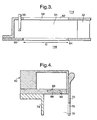
Figure 3 is an enlarged cross-sectional view of part of the primary fuel and air mixing duct shown infigure 2 . -
Figure 4 is an enlarged cross-sectional view of part of the secondary fuel and air mixing duct shown infigure 2 . -
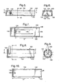
Figure 5 is a cross-sectional view of an alternative fuel and air mixing duct not forming part of the invention. -
Figure 6 is a cross-sectional view in the direction of arrows W-W infigure 5 . -
Figure 7 is a cross-sectional view in the direction of arrows X-X infigure 5 . -
Figure 8 is a cross-sectional view of another alternative fuel and air mixing duct not forming part of the invention. -
Figure 9 is a cross-sectional view in the direction of arrows Y-Y infigure 8 . -
Figure 10 is a cross-sectional view in the direction of arrows Z-Z infigure 8 . -
Figure 11 is a graph comparing the fuel to air ratio fluctuation with radial distance in a radial flow fuel and air mixing duct according to the present invention and a radial flow fuel and air mixing duct according to the prior art. -
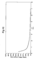
Figure 12 is a graph of the fuel to air ratio of a fuel and air mixing duct according to the present invention divided by the fuel to air ratio of a fuel and air mixing duct according to the prior art against the frequency of fluctuation multiplied by the length of the fuel and air mixing duct divided by the velocity of the fuel and air mixture leaving the fuel and air mixing duct. -
Figure 13 is a cross-sectional view of an alternative fuel and air mixing duct. -
Figure 14 is cross-sectional view in the direction of arrows T-T infigure 13 . -
Figure 15 is a cross-sectional view of a further fuel and air mixing duct. -
Figure 16 is a graph of the fuel to air ratio of fuel and air mixing ducts according to the present invention against the frequency of the fluctuation multiplied by the length of the fuel and air mixing duct divided by the velocity of the fuel and air mixture leaving the fuel and air mixing duct. - An industrial
gas turbine engine 10, shown infigure 1 , comprises in axial flow series aninlet 12, acompressor section 14, acombustion chamber assembly 16, aturbine section 18, apower turbine section 20 and anexhaust 22. Theturbine section 18 is arranged to drive thecompressor section 14 via one or more shafts (not shown). Thepower turbine section 20 is arranged to drive anelectrical generator 26 via ashaft 24. The operation of thegas turbine engine 10 is quite conventional, and will not be discussed further. Alternatively, theturbine section 18 may drive part of thecompressor section 14 via a shaft (not shown) and thepower turbine section 20 may be arranged to drive part of thecompressor section 14 via a shaft (not shown) and is arranged to drive anelectrical generator 26 via ashaft 24. However, thepower turbine section 20 may be arranged to provide drive for other purposes. - The
combustion chamber assembly 16 is shown more clearly infigures 2 ,3 and 4 . Thecombustion chamber assembly 16 comprises a plurality of, for example eight or nine, equally circumferentially spacedtubular combustion chambers 28. The axes of thetubular combustion chambers 28 are arranged to extend in generally radial directions. The inlets of thetubular combustion chambers 28 are at their radially outermost ends and their outlets are at their radially innermost ends. - Each of the
tubular combustion chambers 28 comprises anupstream wall 30 secured to the upstream end of anannular wall 32. A first, upstream,portion 34 of theannular wall 32 defines aprimary combustion zone 36, a second, intermediate,portion 38 of theannular wall 32 defines asecondary combustion zone 40 and a third, downstream,portion 42 of theannular wall 32 defines atertiary combustion zone 44. Thesecond portion 38 of theannular wall 32 has a greater diameter than thefirst portion 34 of theannular wall 32 and similarly thethird portion 42 of theannular wall 32 has a greater diameter than thesecond portion 38 of theannular wall 32. - A plurality of equally circumferentially spaced
transition ducts 46 are provided, and each of thetransition ducts 46 has a circular cross-section at itsupstream end 48. Theupstream end 48 of each of thetransition ducts 46 is located coaxially with the downstream end of a corresponding one of thetubular combustion chambers 28, and each of thetransition ducts 46 connects and seals with an angular section of the nozzle guide vanes. - The
upstream wall 30 of each of thetubular combustion chambers 28 has anaperture 50 to allow the supply of air and fuel into theprimary combustion zone 36. Aradial flow swirler 52 is arranged coaxially with theaperture 50 in theupstream wall 30. - A plurality of
fuel injectors 56 are positioned in a primary fuel andair mixing duct 54 formed upstream of theradial flow swirler 52. Thewalls air mixing duct 54 are provided with a plurality of circumferentially spacedslots air mixing duct 54. Each circumferentially spacedslot air mixing duct 54 over a distance D. Theslots - A central pilot igniter 66 is positioned coaxially with the
aperture 50. The pilot igniter 66 defines a downstream portion of the primary fuel andair mixing duct 54 for the flow of the fuel and air mixture from theradial flow swirler 52 into theprimary combustion zone 36. The pilot igniter 66 turns the fuel and air mixture flowing from the radial flow swirler 52 from a radial direction to an axial direction. The primary fuel and air is mixed together in the primary fuel andair mixing duct 54. - The primary fuel and
air mixing duct 54 reduces in cross-sectional area from theintake aperture 50 at its downstream end. The shape of the primary fuel andair mixing duct 54 produces a constantly accelerating flow through theduct 54. - The
fuel injectors 56 are supplied with fuel from aprimary fuel manifold 68. - An annular secondary fuel and
air mixing duct 70 is provided for each of thetubular combustion chambers 28. Each secondary fuel andair mixing duct 70 is arranged circumferentially around theprimary combustion zone 36 of the correspondingtubular combustion chamber 28. Each of the secondary fuel andair mixing ducts 70 is defined between a secondannular wall 72 and a thirdannular wall 74. The secondannular wall 72 defines the inner extremity of the secondary fuel andair mixing duct 70 and the thirdannular wall 74 defines the outer extremity of the secondary fuel andair mixing duct 70. The secondannular wall 72 of the secondary fuel andair mixing duct 70 has a plurality of circumferentially spacedslots 76 which form a secondary air intake to the secondary fuel andair mixing duct 70. Each circumferentially spacedslot 76 extends axially, longitudinally, in the direction of flow, of the secondary fuel andair mixing duct 70. Theslots 76 extend purely axially. - At the downstream end of the secondary fuel and
air mixing duct 70, the second and thirdannular walls frustoconical wall portion 78 interconnecting thewall portions frustoconical wall portion 78 is provided with a plurality ofapertures 80. Theapertures 80 are arranged to direct the fuel and air mixture into thesecondary combustion zone 40 in a downstream direction towards the axis of thetubular combustion chamber 28. Theapertures 80 may be circular or slots and are of equal flow area. - The secondary fuel and
air mixing duct 70 reduces in cross-sectional area from theintake 76 at its upstream end to theapertures 80 at its downstream end. The shape of the secondary fuel andair mixing duct 70 produces a constantly accelerating flow through theduct 70. - A plurality of
secondary fuel systems 82 are provided, to supply fuel to the secondary fuel andair mixing ducts 70 of each of thetubular combustion chambers 28. Thesecondary fuel system 82 for eachtubular combustion chamber 28 comprises an annularsecondary fuel manifold 84 arranged coaxially with thetubular combustion chamber 28 at the upstream end of the secondary fuel andair mixing duct 70 of thetubular combustion chamber 28. Eachsecondary fuel manifold 84 has a plurality, for example thirty two, of equi-circumferentially-spacedsecondary fuel apertures 86. Each of thesecondary fuel apertures 86 directs the fuel axially of thetubular combustion chamber 28 onto anannular splash plate 88. The fuel flows from thesplash plate 88 through anannular passage 90 in a downstream direction into the secondary fuel andair mixing duct 70 as an annular sheet of fuel. - An annular tertiary fuel and
air mixing duct 92 is provided for each of thetubular combustion chambers 28. Each tertiary fuel andair mixing duct 92 is arranged circumferentially around thesecondary combustion zone 40 of the correspondingtubular combustion chamber 28. Each of the tertiary fuel andair mixing ducts 92 is defined between a fourthannular wall 94 and a fifthannular wall 96. The fourthannular wall 94 defines the inner extremity of the tertiary fuel andair mixing duct 92 and the fifthannular wall 96 defines the outer extremity of the tertiary fuel andair mixing duct 92. The tertiary fuel andair mixing duct 92 has a plurality of circumferentially spacedslots 98 which form a tertiary air intake to the tertiary fuel andair mixing duct 92. Each circumferentially spacedslot 98 extends axially, longitudinally, in the direction of flow, of the tertiary fuel andair mixing duct 92. Theslots 98 extend purely axially. - At the downstream end of the tertiary fuel and
air mixing duct 92, the fourth and fifthannular walls frustoconical wall portion 100 interconnecting thewall portions frustoconical wall portion 100 is provided with a plurality ofapertures 102. Theapertures 102 are arranged to direct the fuel and air mixture into thetertiary combustion zone 44 in a downstream direction towards the axis of thetubular combustion chamber 28. Theapertures 102 may be circular or slots and are of equal flow area. - The tertiary fuel and
air mixing duct 92 reduces in cross-sectional area from theintake 98 at its upstream end to theapertures 102 at its downstream end. The shape of the tertiary fuel andair mixing duct 92 produces a constantly accelerating flow through theduct 92. - A plurality of
tertiary fuel systems 104 are provided, to supply fuel to the tertiary fuel andair mixing ducts 92 of each of thetubular combustion chambers 28. Thetertiary fuel system 104 for eachtubular combustion chamber 28 comprises an annulartertiary fuel manifold 106 positioned at the upstream end of the tertiary fuel andair mixing duct 92. Eachtertiary fuel manifold 106 has a plurality, for example thirty two, of equi-circumferentially spacedtertiary fuel apertures 108. Each of thetertiary fuel apertures 108 directs the fuel axially of thetubular combustion chamber 28 onto anannular splash plate 110. The fuel flows from thesplash plate 110 through theannular passage 112 in a downstream direction into the tertiary fuel andair mixing duct 92 as an annular sheet of fuel. - As discussed previously the fuel and air supplied to the combustion zones is premixed and each of the
combustion zones primary combustion zone 36 flow into thesecondary combustion zone 40 and the products of combustion from thesecondary combustion zone 40 flow into thetertiary combustion zone 44. - Some of the air, indicated by arrow A, for primary combustion flows to a
chamber 114 and this flow through theslots 62 inwall 58 into the primary fuel andair mixing duct 54. The remainder of the air, indicated by arrow B, for primary combustion flows to achamber 116 and this flow through theslots 60 inwall 56 into the primary fuel andair mixing duct 54. The air, indicated by arrow C, for secondary combustion flows to thechamber 116 and this flow through theslots 76 inwall 72 into the secondary fuel andair mixing duct 70. The air, indicated by arrow E, for tertiary combustion flows to the chamber 118 and this flow through theslots 98 inwall 94 into the tertiary fuel andair mixing duct 92. - The combustion process amplifies the pressure fluctuations for the reasons discussed previously and may cause components of the gas turbine engine to become damaged if they have a natural frequency of a vibration mode coinciding with the frequency of the pressure fluctuations. Alternatively the amplitude of the pressure fluctuations may be sufficiently great to cause damage to the components of the gas turbine engine.
- The pressure fluctuations, or pressure waves, in the combustion chamber produce fluctuations in the fuel to air ratio at the exit of the fuel and air mixing ducts. The pressure fluctuations in the airflow and the constant supply of fuel into the fuel and air mixing ducts of the tubular combustion chambers results in the fluctuating fuel to air ratio at the exit of the fuel and air mixing ducts.
- Consider the equation:-

Where U is the velocity of the air, M is the mass, P is the pressure, Δu is the change in velocity, Δp is the change in pressure, FAR is the fuel to air ratio and Δ(FAR) is the change in the fuel to air ratio. - Thus in a typical fuel and air mixing duct, if Δp/P is about 1%, then Δu/U is about 30% and hence the Δ(FAR)/FAR is about 30% into the combustion chamber.
- The present invention seeks to provide a fuel and air mixing duct which supplies a mixture of fuel and air into the combustion chamber at a more constant fuel to air ratio. The present invention provides at least one point of fuel injection into the fuel and air mixing duct and a plurality of points of air injection into the fuel and air mixing duct. The air injection points are spaced apart longitudinally, along the slots, in the direction of flow of the fuel and air mixing duct. The pressure of the air at the longitudinally spaced air injection points at any instant in time is different. Thus as the fuel and air mixture flows along the fuel and air mixing duct the fuel and air mixture becomes weaker due to the additional air. More importantly the maximum difference between the actual fuel to air ratio and the average fuel to air ratio becomes relatively low, see line F in
figure 11 . However for a single fuel injection point and a single air injection point the maximum difference between the actual fuel to air ratio and the average fuel to air ratio remains relatively high, see line G infigure 11 . - A single point of fuel injection means that there is one or more fuel injectors arranged at the same distance from the combustion zone, or alternatively one or more fuel injectors are arranged at a fixed time delay from the combustion zone. Thus the fuel injectors are arranged at a position such that the time of travel from the point of fuel injection to the combustion zone is the same for all of the fuel injectors.
- Calculations show, see
figure 12 , that the variation in the fuel to air ratio for a fuel and air mixing duct with a single fuel injection point and multiple air injection points are a few percent of the variation in the fuel to air ratio for a fuel and air mixing duct with a single fuel injection point and a single air injection point if the volume of the fuel and air mixing duct is such that the following equation is satisfied
Where L is the length of the fuel and air mixing duct, F is the frequency, U is the exit velocity of the fuel and air mixture and X is a number greater than 2. The greater the number X, the lower the variation in the fuel to air ratio. For example with X = 2, the variation is about 7%, for X = 3, the variation is about 4%, for X = 4, the variation is about 3%. Preferably X is a number greater than 3, more preferably X is a number greater than 4 and more preferably X is a number greater than 5. - For a tubular combustion chamber, the frequency of the lowest acoustic mode of the combustion chamber is

Where F is the frequency of the pressure fluctuations, c is the average speed of sound inside the combustion chamber and L is the overall length of the tubular combustion chamber. - For an annular combustion chamber, the frequency of the lowest acoustic mode of the combustion chamber is

Where F is the frequency of the pressure fluctuations, c is the average speed of sound inside the combustion chamber and D is the diameter of the annular combustion chamber. - For the present invention to work effectively the air injectors, slots, need to extend over a length X such that

Where X is the length of the slots and U is the average velocity of the air inside the mixing duct. Preferably FX/U > 2. - This results in the following design rules, for a tubular combustion chamber X > 4LU/c or more preferably X > 8LU/c and for an annular combustion chamber X > nDU/c or more preferably X > 2πDU/c.
- The above equations indicate that as the operating temperature of the combustion chamber increases, the speed of sound increases and therefore the amount of damping by the invention increases. This is an advantage of the present invention.
- The progressive introduction of air along the length of the fuel and air mixing duct through the slots results in a number of physical mechanisms which contribute to the reduction, preferably elimination, of the pressure fluctuations, pressure waves or instabilities, in the combustion chamber. The physical mechanisms are the creation of a low velocity region, integration of the fuel to air ratio fluctuations, damping of pressure waves and destruction of phase relationships. The advantage of the slots over apertures is that there is a narrow residence time distribution, hence a reduced risk of autoignition of the fuel, while maintaining excellent fuel to air ratio characteristics.
- The airflow in the vicinity of the fuel injector experiences fluctuations in its bulk velocity due to the pressure fluctuations in the fuel and air mixing duct. This creates a local fluctuation in fuel concentration, a local fuel to air ratio, which then flows downstream at the bulk velocity of the air in the fuel and air mixing duct. Due to the mixing of the fuel and air in the fuel and air mixing duct these fuel to air ratio fluctuations normally diffuse out, although the process is quite slow. However, if the local convective velocity is low and the local turbulent intensity is high, as in the present invention, any fuel to air ratio fluctuations are substantially dissipated by the time the fuel to air ratio fluctuations reach the combustion chamber.
- Any fluctuation in the local fuel to air ratio in the vicinity of the fuel injector flows downstream and the progressive introduction of air along the length of the fuel and air mixing duct integrates out any fluctuations in the local fuel to air ratio due to the fuel injector. This is because the pressure of the air supplied along the length of the slots of air injectors fluctuates with time. If the average time of travel of a fluid particle from the vicinity of the fuel injector to the downstream end of the fuel and air mixing duct is longer than the time period of the pressure fluctuations, then the fluid particle originating from the vicinity of the fuel injector is subjected to a number of cycles of becoming leaner and richer that average out the initial fuel concentration fluctuation. This determines the spatial extent of the air injectors, i.e. the length D of the fuel and air mixing duct containing air injectors. This also determines the width, or cross-sectional area, of the fuel and air mixing duct as this affects the total residence time in the fuel and air mixing duct.
- The average air velocity through the slots is chosen so that the air injectors or slots are sensitive to pressure fluctuations originating in the combustion chamber. As a pressure wave propagates from the downstream end of the fuel and air mixing duct towards the fuel injector it progressively loses amplitude because energy is used fluctuating the air pressure in the air injectors. This reduces the possibility of the pressure fluctuations producing a local fuel to air ratio fluctuation in the vicinity of the fuel injector. This also completely changes the coupling between the interior and exterior of the combustion chamber.
- A consistent relationship is required between the pressure fluctuations inside the combustion chamber and the fluctuations in the chemical energy supplied to the combustion chamber in order for the occurrence of combustion instability. The chemical energy input to the combustion chamber is proportional to the strength of the fuel and air mixture supplied to the combustion chamber and the air velocity at the exit of the fuel and air mixing duct. The plurality of air injectors integrate out the pressure fluctuations and the fluctuations in the strength of the fuel and air mixture. Also any fuel to air ratio fluctuations present at the downstream end of the fuel and air mixing duct are uncorrelated with the pressure fluctuations that produced them. The possibility of positive reinforcement of pressure fluctuations or fuel to air ratio fluctuations is reduced.
- Mixing of the fuel and air in the fuel and air mixing duct is achieved by the vortex flow set in motion by the slots.
- A further advantage of the use of slots as air injectors is that the risk of auto ignition of the fuel is reduced because the fuel residence time in the fuel and air mixing duct is less uncertain than with a plurality of spaced apertures. The slots eliminate the wakes and boundary layer transverse vortices formed by the discrete apertures in cross flow relationship. The slots are staggered on opposite walls to avoid a stagnation zone on the wall opposite a slot. The slots are made as narrow as possible in order to reduce the wake at the trailing edge of the slot, typically the slots have a width of 1mm. The distance between slots is about the same as the distance between the walls of the fuel and air mixing duct. The slots are aligned with the direction of flow of the fuel and air mixture to avoid the formation of stagnant zones in the wakes of the slots.
- Another advantage is that the slots create large scale vortex motion which promotes effective mixing of the fuel and air in the fuel and air mixing duct.
- Another advantage is that it is easier to make a small number of slots than a larger number of apertures.
- An alternative fuel and
air mixing duct 120 not forming part of the invention is shown infigures 5, 6 and 7 . A rectangular cross-section fuel andair mixing duct 120 comprises foursidewalls walls slots air mixing duct 120. Theslots air mixing duct 120. Theslots 130 in thewall 124 are staggered from theslots 132 in thewall 128 so that eachslot 130 in thewall 124 is equi-distant from twoadjacent slots 132 in thewall 128 and visa-versa. Asingle fuel injector 140 is provided to supply fuel into theupstream end 134 of the fuel andair mixing duct 120. Thefuel injector 140 is supplied with fuel from afuel manifold 138. - Another alternative fuel and
air mixing duct 150 not forming part of the invention is shown infigures 8, 9 and 10 . A circular cross-section fuel andair mixing duct 150 comprises atubular wall 152 which has a plurality of circumferentially spacedslots 154 which form an air intake to the fuel andair mixing duct 150. Theslots 154 extend longitudinally, axially, of the fuel andair mixing duct 150. Asingle fuel injector 160 is provided to supply fuel into theupstream end 156 of the fuel andair mixing duct 150. Thefuel injector 160 is supplied with fuel from a fuel manifold. - Another primary fuel and
air mixing duct 170 according to one embodiment of the present invention is shown infigures 13 and 14 . The primary fuel andair mixing duct 170 compriseswalls slots air mixing duct 170. Theslots 178 in thewall 174 are staggered from theslots 180 in thewall 176 so that eachslot 178 in thewall 174 is equi-distant from twoadjacent slots 180 in thewall 176 and visa-versa. The primary fuel andair mixing duct 170 also has a plurality offuel injectors 172 positioned in the primary fuel andair mixing duct 170 upstream of theslots apertures 182 are provided to form part of the primary air intake upstream of thefuel injectors 172. Theapertures 182 supply up to 40% of the primary air upstream of thefuel injectors 172. Theapertures 182 are provided to prevent the formation of a stagnant zone, a zone with no net velocity, at the upstream end of the primary fuel andair mixing duct 170. The stagnant zone mainly consists of fuel and a small fraction of air, in operation, which results in long residence times for the fuel with an increased risk of auto ignition of the fuel in the primary fuel andair mixing duct 170. Theapertures 182 minimise the risk of auto ignition. The primary fuel andair mixing duct 170 also increases in cross-sectional area, as shown, in a downstream direction. The introduction of air upstream of thefuel injectors 172 only has a minor effect on the fuel to air ratio as shown infigure 16 , where line H indicates the fluctuation in the amplitude of the fuel to air ratio infigure 3 and line I indicates the fluctuation in the amplitude of the fuel to air ratio infigures 13 and 14 . - A further secondary fuel and
air mixing duct 190 according to another embodiment of the present invention is shown infigure 15 and is similar to that shown infigure 4 . The secondary fuel andair mixing duct 190 comprises innerannular wall 194 and outerannular wall 196. The inner and outerannular walls slots air mixing duct 190. The secondary fuel andair mixing duct 190 also has an annularfuel injector slot 192 positioned in the secondary fuel andair mixing duct 190 upstream of theslots fuel injector slot 192. The apertures 202 may supply up to 20% of the secondary air, preferably up to 10% of the secondary air. The apertures 202 also prevent the formation of a stagnant zone and auto ignition, at the upstream end of the secondary fuel andair mixing duct 190. The secondary fuel andair mixing duct 190 also increases in cross-sectional area, as shown, in a downstream direction. A similar arrangement of additional apertures may be applied to the tertiary fuel and air mixing duct to prevent the formation of a stagnant zone and auto ignition. - The upstream ends of the slots may be positioned upstream of the fuel injectors to avoid fuel being trapped upstream of a vortex associated with the upstream edge of a blunt body or air jet.
- The slots in the walls of the fuel and air mixing duct may be arranged perpendicularly to the walls of the fuel and air mixing duct or at any other suitable angle.
- The fuel supplied by the fuel injector may be a liquid fuel or a gaseous fuel.
- The invention is also applicable to other fuel and air mixing ducts. For example the fuel and air mixing ducts may comprise any suitable shape, or cross-section, as long as there are a plurality of points of injection of air arranged longitudinally in a slot, in the direction of flow through the fuel and air mixing duct, into the fuel and air mixing duct. The slots may be provided in any one or more of the walls defining the fuel and air mixing duct.
- The invention is also applicable to other air injectors, for example hollow slotted members may be provided which extend into the fuel and air mixing duct to supply air into the fuel and air mixing duct.
- The fuel and air mixing duct may have a swirler, alternatively it may not have a swirler. The fuel and air mixing duct may have two coaxial counter swirling swirlers. The swirler may be an axial flow swirler.
- Although the invention has referred to an industrial gas turbine engine it is equally applicable to an aero gas turbine engine or a marine gas turbine engine.
Claims (17)
- A tubular combustion chamber (28) comprising at least one combustion zone (36,40,44) defined by at least one peripheral annular wall (32), at least one fuel and air mixing duct (70,92,190) for supplying a fuel and air mixture to the at least one combustion zone (36,40,44), the at least one fuel and air mixing duct (70, 92, 190) having an upstream end and a downstream end, fuel injection means (90, 112, 192) for supplying fuel into the at least one fuel and air mixing duct (70,92,190), air injection means (76,98,198,200,202) for supplying air into the at least one fuel and air mixing duct (70,92,190), the pressure of the air supplied to the at least one fuel and air mixing duct (70,92,190) fluctuating, wherein the air injection means (76,98,198,200,202) comprise a plurality of air injectors (76,98,198,200) spaced apart transversely to the direction of flow through the at least one fuel and air mixing duct (70,92,190), each air injector (76,98, 198, 200) comprising a slot extending in the direction of flow through the at least one fuel and air mixing duct (70,92, 190) to reduce the magnitude of the fluctuations in the fuel to air ratio of the fuel and air mixture supplied into the at least one combustion zone (36,40,44),
wherein the combustion chamber (28) comprises a primary combustion zone (36) and a secondary combustion zone (40) downstream of the primary combustion zone (36),
wherein the at least one fuel and air mixing duct (70, 92,190) comprises a single annular fuel and air mixing duct (70, 92, 190), the plurality of air injectors (76, 98, 198, 200) being circumferentially spaced apart and the plurality of air injectors (76, 98, 198, 200) extending axially, in the direction of the longitudinal axis of the tubular combustion chamber, the single annular fuel and air mixing duct (70, 92, 190) comprising an inner annular wall (72, 94, 194) and an outer annular wall (74, 96, 196), the plurality of air injectors (76, 98, 198, 200) being arranged in the inner and outer annular walls (72, 94, 74, 96, 194, 196), characterised in that the plurality of air injectors (76, 98, 198)in the inner annular wall (72,94,194) are staggered circumferentially with respect to the plurality of air injectors (76,98,200)in the outer annular wall (74, 96, 196). - A tubular combustion chamber (28) comprising at least one combustion zone (36,40,44) defined by at least one peripheral annular wall (32), at least one fuel and air mixing duct (54,170) for supplying a fuel and air mixture to the at least one combustion zone (36,40,44), the at least one fuel and air mixing duct (54,170) having an upstream end and a downstream end, fuel injection means (56,172) for supplying fuel into the at least one fuel and air mixing duct (54,170), air injection means (62,64,178,180,182) for supplying air into the at least one fuel and air mixing duct (54,170), the pressure of the air supplied to the at least one fuel and air mixing duct (54,170) fluctuating,
wherein the air injection means (62,64,178,180, 182) comprise a plurality of air injectors (62,64,178,180) spaced apart transversely to the direction of flow through the at least one fuel and air mixing duct (54,170), each air injector (62,64,178,180) comprising a slot extending in the direction of flow through the at least one fuel and air mixing duct (54,170) to reduce the magnitude of the fluctuations in the fuel to air ratio of the fuel and air mixture supplied into the at least one combustion zone (36,40,44),
wherein the at least one fuel and air mixing duct (54, 170) comprises a radial fuel and air mixing duct, the plurality of air injectors (62,64,178,180) being circumferentially spaced apart and the plurality of air injectors (62, 64, 178, 180) extending radially with respect to the longitudinal axis of the tubular combustion chamber, the radial fuel and air mixing duct (54,170) comprising a first radial wall (58,174) and a second radial wall (60,176) spaced apart axially in the direction of the longitudinal axis of the tubular combustion chamber, the plurality of air injectors (62, 64, 178, 180) being provided in the first and second radial walls (58, 60, 174, 176),
characterised in that the plurality of air injectors (62, 178) in the first radial wall (58,174) are staggered circumferentially with respect to the plurality of air injectors (64, 180) in the second radial wall (60, 176). - A combustion chamber as claimed in claim 2 wherein the combustion chamber comprises a primary combustion zone (36) and a secondary combustion zone (40) downstream of the primary combustion zone (36).
- A combustion chamber as claimed in claim 1 or claim 3 wherein the combustion chamber (28) comprises a primary combustion zone (36), a secondary combustion zone (40) downstream of the primary combustion zone (36) and a tertiary combustion zone (44) downstream of the secondary combustion zone (40).
- A combustion chamber as claimed in claim 3 or claim 4 as dependent on claim 3 wherein the radial fuel and air mixing duct (54, 170) supplies fuel and air into the primary combustion zone (36).
- A combustion chamber as claimed in claim 1 or claim 4 as dependent on claim 1 wherein the single annular fuel and air mixing duct (70, 190) supplies fuel and air into the secondary combustion zone (40).
- A combustion chamber as claimed in claim 4 as dependent on claim 1 wherein the single annular fuel and air mixing duct (92, 190) supplies fuel and air into the tertiary combustion zone (44).
- A combustion chamber as claimed in any of claims 1 to 7 wherein the fuel injection means (172, 192) is arranged between the upstream end and the downstream end of the or each fuel and air mixing duct (170, 190), at least a portion (182, 202) of the plurality of air injectors (178, 180, 182, 198, 200, 202) are arranged upstream of the fuel injection means (172, 192) and at least a portion (178, 180, 198, 200) of the plurality of air injectors (178,180,182, 198, 200, 202) are arranged downstream of the fuel injection means (172,192).
- A combustion chamber as claimed in any of claims 1 to 8 wherein each one of the plurality of air injectors (62,64, 76, 98, 178,180, 198, 200) at the downstream end of the or each fuel and air mixing duct (54, 70, 92, 170, 190) is arranged to supply more air into the fuel and air mixing duct than each one of the plurality of air injectors (62, 64, 76, 98, 178, 180, 182, 198, 200, 202) at the upstream end of the or each fuel and air mixing duct.
- A combustion chamber as claimed in any of claims 1 to 9 wherein each one of the plurality of air injectors (62, 64, 76, 98, 178,180, 198, 200) at a first position in the direction of flow through the or each fuel and air mixing duct (54, 70, 92, 170, 190) is arranged to supply more air into the fuel and air mixing duct than said plurality of air injectors (62, 64, 76, 98, 178, 180, 182, 198, 200, 202) upstream of the first position in the fuel and air mixing duct.
- A combustion chamber as claimed in claim 10 wherein said each one of the plurality of air injectors at the first position in the or each fuel and air mixing duct is arranged to supply less air into the fuel and air mixing duct than said plurality of air injectors (62,64, 76, 98, 178,180, 198, 200)downstream of the first position in the or each fuel and air mixing duct.
- A combustion chamber as claimed in any of claims 1 to 11 wherein the volume of the or each fuel and air mixing duct (54,70,92, 170, 190) being arranged such that the average travel time from the fuel injection means (56,90,112, 172, 192) to the downstream end of the fuel and air mixing duct is greater than the time period of the fluctuation.
- A combustion chamber as claimed in any of claims 1 to 11 wherein the volume of the fuel and air mixing duct (54,70,92, 170, 190) being arranged such that the length of the fuel and air mixing duct multiplied by the frequency of the fluctuations divided by the velocity of the fuel and air leaving the downstream end of the fuel and air mixing duct is at least one.
- A combustion chamber as claimed in claim 13 wherein said volume of the or each fuel and air mixing duct being arranged such that the length of the fuel and air mixing duct multiplied by the frequency of the fluctuations divided by the velocity of the fuel and air leaving the downstream end of the fuel and air mixing duct is at least two.
- A combustion chamber as claimed in any of claims 1 to 11 wherein the plurality of air injectors (62,64,76,98, 178, 180, 198, 200) extend in the direction of flow through each fuel and air mixing duct (54,70,92, 170, 190) over a length (D) equal to half the wavelength of the fluctuations of the air supplied to the or each fuel and air mixing duct.
- A combustion chamber as claimed in any of claims 1 to 14 wherein the length (D) of an air injector (62,64,76,98, 178, 180, 198, 200) in the direction of flow through the or each fuel and air mixing duct (54,70,92, 170, 190) multiplied by the frequency of the fluctuations divided by the velocity of the fuel and air inside the fuel and air mixing duct is at least one.
- A combustion chamber as claimed in claim 16 wherein said length (D) of the air injector multiplied by said frequency of the fluctuations divided by said average velocity of the fuel and air is at least two.
Applications Claiming Priority (2)
| Application Number | Priority Date | Filing Date | Title |
|---|---|---|---|
| GBGB0111788.6A GB0111788D0 (en) | 2001-05-15 | 2001-05-15 | A combustion chamber |
| GB0111788 | 2001-05-15 |
Publications (3)
| Publication Number | Publication Date |
|---|---|
| EP1260768A2 EP1260768A2 (en) | 2002-11-27 |
| EP1260768A3 EP1260768A3 (en) | 2004-11-17 |
| EP1260768B1 true EP1260768B1 (en) | 2014-07-23 |
Family
ID=9914629
Family Applications (1)
| Application Number | Title | Priority Date | Filing Date |
|---|---|---|---|
| EP02253028.1A Expired - Lifetime EP1260768B1 (en) | 2001-05-15 | 2002-04-29 | A tubular combustion chamber |
Country Status (4)
| Country | Link |
|---|---|
| US (2) | US6732527B2 (en) |
| EP (1) | EP1260768B1 (en) |
| CA (1) | CA2384336C (en) |
| GB (1) | GB0111788D0 (en) |
Families Citing this family (55)
| Publication number | Priority date | Publication date | Assignee | Title |
|---|---|---|---|---|
| US7054271B2 (en) | 1996-12-06 | 2006-05-30 | Ipco, Llc | Wireless network system and method for providing same |
| US8982856B2 (en) | 1996-12-06 | 2015-03-17 | Ipco, Llc | Systems and methods for facilitating wireless network communication, satellite-based wireless network systems, and aircraft-based wireless network systems, and related methods |
| US6233327B1 (en) | 1997-02-14 | 2001-05-15 | Statsignal Systems, Inc. | Multi-function general purpose transceiver |
| US7079810B2 (en) | 1997-02-14 | 2006-07-18 | Statsignal Ipc, Llc | System and method for communicating with a remote communication unit via the public switched telephone network (PSTN) |
| US7137550B1 (en) | 1997-02-14 | 2006-11-21 | Statsignal Ipc, Llc | Transmitter for accessing automated financial transaction machines |
| US6914533B2 (en) | 1998-06-22 | 2005-07-05 | Statsignal Ipc Llc | System and method for accessing residential monitoring devices |
| US6891838B1 (en) | 1998-06-22 | 2005-05-10 | Statsignal Ipc, Llc | System and method for monitoring and controlling residential devices |
| US8410931B2 (en) | 1998-06-22 | 2013-04-02 | Sipco, Llc | Mobile inventory unit monitoring systems and methods |
| US6914893B2 (en) | 1998-06-22 | 2005-07-05 | Statsignal Ipc, Llc | System and method for monitoring and controlling remote devices |
| US6437692B1 (en) | 1998-06-22 | 2002-08-20 | Statsignal Systems, Inc. | System and method for monitoring and controlling remote devices |
| US7103511B2 (en) | 1998-10-14 | 2006-09-05 | Statsignal Ipc, Llc | Wireless communication networks for providing remote monitoring of devices |
| US7650425B2 (en) | 1999-03-18 | 2010-01-19 | Sipco, Llc | System and method for controlling communication between a host computer and communication devices associated with remote devices in an automated monitoring system |
| US7263073B2 (en) | 1999-03-18 | 2007-08-28 | Statsignal Ipc, Llc | Systems and methods for enabling a mobile user to notify an automated monitoring system of an emergency situation |
| GB0111788D0 (en) * | 2001-05-15 | 2001-07-04 | Rolls Royce Plc | A combustion chamber |
| US7480501B2 (en) | 2001-10-24 | 2009-01-20 | Statsignal Ipc, Llc | System and method for transmitting an emergency message over an integrated wireless network |
| US8489063B2 (en) | 2001-10-24 | 2013-07-16 | Sipco, Llc | Systems and methods for providing emergency messages to a mobile device |
| US7424527B2 (en) | 2001-10-30 | 2008-09-09 | Sipco, Llc | System and method for transmitting pollution information over an integrated wireless network |
| ITMI20012781A1 (en) * | 2001-12-21 | 2003-06-21 | Nuovo Pignone Spa | IMPROVED ASSEMBLY OF PRE-MIXING CHAMBER AND COMBUSTION CHAMBER, LOW POLLUTING EMISSIONS FOR GAS TURBINES WITH FUEL |
| GB2390150A (en) * | 2002-06-26 | 2003-12-31 | Alstom | Reheat combustion system for a gas turbine including an accoustic screen |
| GB0230070D0 (en) * | 2002-12-23 | 2003-01-29 | Bowman Power Systems Ltd | A combustion device |
| EP1460339A1 (en) * | 2003-03-21 | 2004-09-22 | Siemens Aktiengesellschaft | Gas turbine |
| US7140184B2 (en) * | 2003-12-05 | 2006-11-28 | United Technologies Corporation | Fuel injection method and apparatus for a combustor |
| ITMI20032621A1 (en) * | 2003-12-30 | 2005-06-30 | Nuovo Pignone Spa | COMBUSTION SYSTEM WITH LOW POLLUTING EMISSIONS |
| US7756086B2 (en) | 2004-03-03 | 2010-07-13 | Sipco, Llc | Method for communicating in dual-modes |
| US8031650B2 (en) | 2004-03-03 | 2011-10-04 | Sipco, Llc | System and method for monitoring remote devices with a dual-mode wireless communication protocol |
| US20060107667A1 (en) * | 2004-11-22 | 2006-05-25 | Haynes Joel M | Trapped vortex combustor cavity manifold for gas turbine engine |
| US9439126B2 (en) | 2005-01-25 | 2016-09-06 | Sipco, Llc | Wireless network protocol system and methods |
| WO2007033306A2 (en) * | 2005-09-13 | 2007-03-22 | Rolls-Royce Corporation, Ltd. | Gas turbine engine combustion systems |
| US7703288B2 (en) * | 2005-09-30 | 2010-04-27 | Solar Turbines Inc. | Fuel nozzle having swirler-integrated radial fuel jet |
| US20070074518A1 (en) * | 2005-09-30 | 2007-04-05 | Solar Turbines Incorporated | Turbine engine having acoustically tuned fuel nozzle |
| US8881531B2 (en) * | 2005-12-14 | 2014-11-11 | Rolls-Royce Power Engineering Plc | Gas turbine engine premix injectors |
| US8061141B2 (en) * | 2007-09-27 | 2011-11-22 | Siemens Energy, Inc. | Combustor assembly including one or more resonator assemblies and process for forming same |
| US8028512B2 (en) | 2007-11-28 | 2011-10-04 | Solar Turbines Inc. | Active combustion control for a turbine engine |
| EP2107313A1 (en) * | 2008-04-01 | 2009-10-07 | Siemens Aktiengesellschaft | Fuel staging in a burner |
| US8176739B2 (en) * | 2008-07-17 | 2012-05-15 | General Electric Company | Coanda injection system for axially staged low emission combustors |
| US20100236245A1 (en) * | 2009-03-19 | 2010-09-23 | Johnson Clifford E | Gas Turbine Combustion System |
| US8646703B2 (en) * | 2011-08-18 | 2014-02-11 | General Electric Company | Flow adjustment orifice systems for fuel nozzles |
| US9140455B2 (en) * | 2012-01-04 | 2015-09-22 | General Electric Company | Flowsleeve of a turbomachine component |
| US20140033719A1 (en) * | 2012-08-02 | 2014-02-06 | Rahul Ravindra Kulkarni | Multi-step combustor |
| US9212823B2 (en) | 2012-09-06 | 2015-12-15 | General Electric Company | Systems and methods for suppressing combustion driven pressure fluctuations with a premix combustor having multiple premix times |
| US9404659B2 (en) * | 2012-12-17 | 2016-08-02 | General Electric Company | Systems and methods for late lean injection premixing |
| US9217373B2 (en) | 2013-02-27 | 2015-12-22 | General Electric Company | Fuel nozzle for reducing modal coupling of combustion dynamics |
| US11143407B2 (en) | 2013-06-11 | 2021-10-12 | Raytheon Technologies Corporation | Combustor with axial staging for a gas turbine engine |
| US20150167980A1 (en) * | 2013-12-18 | 2015-06-18 | Jared M. Pent | Axial stage injection dual frequency resonator for a combustor of a gas turbine engine |
| WO2018144006A1 (en) | 2017-02-03 | 2018-08-09 | Siemens Aktiengesellschaft | Method for normalizing fuel-air mixture within a combustor |
| WO2018144008A1 (en) | 2017-02-03 | 2018-08-09 | Siemens Aktiengesellschaft | Combustor with three-dimensional lattice premixer |
| US11262073B2 (en) | 2017-05-02 | 2022-03-01 | General Electric Company | Trapped vortex combustor for a gas turbine engine with a driver airflow channel |
| ES2901604T3 (en) | 2017-05-16 | 2022-03-23 | Siemens Energy Global Gmbh & Co Kg | Binary fuel phasing scheme to improve emissions regulation in lean premixed gas turbine combustion |
| US11286884B2 (en) | 2018-12-12 | 2022-03-29 | General Electric Company | Combustion section and fuel injector assembly for a heat engine |
| US11643198B2 (en) * | 2019-01-15 | 2023-05-09 | Curtis Miller | Vertical lift single engine vehicle system |
| US11506384B2 (en) * | 2019-02-22 | 2022-11-22 | Dyc Turbines | Free-vortex combustor |
| CN110631049B (en) * | 2019-10-12 | 2020-12-11 | 中国科学院工程热物理研究所 | Gas Turbine Soft Combustor |
| US11754288B2 (en) | 2020-12-09 | 2023-09-12 | General Electric Company | Combustor mixing assembly |
| CN113757720B (en) * | 2021-09-18 | 2023-01-31 | 北京航空航天大学 | Combustion oscillation control device and method and combustion chamber |
| US12222104B2 (en) | 2022-03-21 | 2025-02-11 | General Electric Company | Turbine engine combustor and combustor liner |
Family Cites Families (21)
| Publication number | Priority date | Publication date | Assignee | Title |
|---|---|---|---|---|
| US2560074A (en) * | 1948-12-21 | 1951-07-10 | Lummus Co | Method and apparatus for burning fuel |
| US3919840A (en) * | 1973-04-18 | 1975-11-18 | United Technologies Corp | Combustion chamber for dissimilar fluids in swirling flow relationship |
| GB1489339A (en) | 1973-11-30 | 1977-10-19 | Rolls Royce | Gas turbine engine combustion chambers |
| US4044553A (en) | 1976-08-16 | 1977-08-30 | General Motors Corporation | Variable geometry swirler |
| US4271675A (en) | 1977-10-21 | 1981-06-09 | Rolls-Royce Limited | Combustion apparatus for gas turbine engines |
| US4263780A (en) * | 1979-09-28 | 1981-04-28 | General Motors Corporation | Lean prechamber outflow combustor with sets of primary air entrances |
| US4412414A (en) * | 1980-09-22 | 1983-11-01 | General Motors Corporation | Heavy fuel combustor |
| EP0554325B1 (en) | 1990-10-23 | 1995-07-26 | ROLLS-ROYCE plc | Gasturbine combustion chamber and method of operation thereof |
| GB9023004D0 (en) * | 1990-10-23 | 1990-12-05 | Rolls Royce Plc | A gas turbine engine combustion chamber and a method of operating a gas turbine engine combustion chamber |
| US5235814A (en) * | 1991-08-01 | 1993-08-17 | General Electric Company | Flashback resistant fuel staged premixed combustor |
| US6220034B1 (en) * | 1993-07-07 | 2001-04-24 | R. Jan Mowill | Convectively cooled, single stage, fully premixed controllable fuel/air combustor |
| GB9325708D0 (en) * | 1993-12-16 | 1994-02-16 | Rolls Royce Plc | A gas turbine engine combustion chamber |
| GB9410233D0 (en) * | 1994-05-21 | 1994-07-06 | Rolls Royce Plc | A gas turbine engine combustion chamber |
| US5636510A (en) * | 1994-05-25 | 1997-06-10 | Westinghouse Electric Corporation | Gas turbine topping combustor |
| US5943866A (en) * | 1994-10-03 | 1999-08-31 | General Electric Company | Dynamically uncoupled low NOx combustor having multiple premixers with axial staging |
| US5850732A (en) * | 1997-05-13 | 1998-12-22 | Capstone Turbine Corporation | Low emissions combustion system for a gas turbine engine |
| US6176087B1 (en) | 1997-12-15 | 2001-01-23 | United Technologies Corporation | Bluff body premixing fuel injector and method for premixing fuel and air |
| US6141954A (en) | 1998-05-18 | 2000-11-07 | United Technologies Corporation | Premixing fuel injector with improved flame disgorgement capacity |
| GB9929601D0 (en) * | 1999-12-16 | 2000-02-09 | Rolls Royce Plc | A combustion chamber |
| US6298667B1 (en) * | 2000-06-22 | 2001-10-09 | General Electric Company | Modular combustor dome |
| GB0111788D0 (en) * | 2001-05-15 | 2001-07-04 | Rolls Royce Plc | A combustion chamber |
-
2001
- 2001-05-15 GB GBGB0111788.6A patent/GB0111788D0/en not_active Ceased
-
2002
- 2002-04-29 EP EP02253028.1A patent/EP1260768B1/en not_active Expired - Lifetime
- 2002-05-01 CA CA2384336A patent/CA2384336C/en not_active Expired - Lifetime
- 2002-05-01 US US10/135,690 patent/US6732527B2/en not_active Expired - Lifetime
-
2003
- 2003-12-30 US US10/747,401 patent/US6959550B2/en not_active Expired - Lifetime
Also Published As
| Publication number | Publication date |
|---|---|
| US6959550B2 (en) | 2005-11-01 |
| EP1260768A2 (en) | 2002-11-27 |
| US6732527B2 (en) | 2004-05-11 |
| US20040154301A1 (en) | 2004-08-12 |
| CA2384336C (en) | 2010-12-14 |
| EP1260768A3 (en) | 2004-11-17 |
| US20020172904A1 (en) | 2002-11-21 |
| GB0111788D0 (en) | 2001-07-04 |
| CA2384336A1 (en) | 2002-11-15 |
Similar Documents
| Publication | Publication Date | Title |
|---|---|---|
| CA2384336C (en) | A combustion chamber | |
| CA2328283C (en) | A staged combustion chamber for a gas turbine | |
| EP0924411B1 (en) | Fluid manifold | |
| EP0961907B1 (en) | Combustor arrangement | |
| EP0982545B1 (en) | A combustion chamber and method of operation | |
| US10072846B2 (en) | Trapped vortex cavity staging in a combustor | |
| EP1180646B1 (en) | A combustion chamber | |
| US5558515A (en) | Premixing burner | |
| EP1067337B1 (en) | Combustion chamber with staged fuel injection | |
| KR101749875B1 (en) | Gas turbine combustor and gas turbine engine equipped with same | |
| EP0732546B1 (en) | Combustor and operating method for gas- or liquid-fuelled turbine | |
| EP1672282B1 (en) | Method and apparatus for decreasing combustor acoustics | |
| JP2010223577A (en) | Swirl, method for preventing backfire in burner equipped with at least one swirler, and burner | |
| JP2010223577A6 (en) | Swirl, method for preventing backfire in burner equipped with at least one swirler, and burner | |
| CN110793061A (en) | Dilution structures for gas turbine engine combustors | |
| EP2041494B1 (en) | Gas turbine engine premix injectors | |
| JP3192055B2 (en) | Gas turbine combustor | |
| US8596071B2 (en) | Method and apparatus for assembling a gas turbine engine | |
| EP1801503A2 (en) | Combustor nozzle | |
| JPH04283315A (en) | Combustor liner |
Legal Events
| Date | Code | Title | Description |
|---|---|---|---|
| PUAI | Public reference made under article 153(3) epc to a published international application that has entered the european phase |
Free format text: ORIGINAL CODE: 0009012 |
|
| AK | Designated contracting states |
Kind code of ref document: A2 Designated state(s): AT BE CH CY DE DK ES FI FR GB GR IE IT LI LU MC NL PT SE TR |
|
| AX | Request for extension of the european patent |
Free format text: AL;LT;LV;MK;RO;SI |
|
| PUAL | Search report despatched |
Free format text: ORIGINAL CODE: 0009013 |
|
| AK | Designated contracting states |
Kind code of ref document: A3 Designated state(s): AT BE CH CY DE DK ES FI FR GB GR IE IT LI LU MC NL PT SE TR |
|
| AX | Request for extension of the european patent |
Extension state: AL LT LV MK RO SI |
|
| 17P | Request for examination filed |
Effective date: 20041117 |
|
| AKX | Designation fees paid |
Designated state(s): CH DE FR GB LI SE |
|
| GRAP | Despatch of communication of intention to grant a patent |
Free format text: ORIGINAL CODE: EPIDOSNIGR1 |
|
| INTG | Intention to grant announced |
Effective date: 20140424 |
|
| GRAS | Grant fee paid |
Free format text: ORIGINAL CODE: EPIDOSNIGR3 |
|
| GRAA | (expected) grant |
Free format text: ORIGINAL CODE: 0009210 |
|
| AK | Designated contracting states |
Kind code of ref document: B1 Designated state(s): CH DE FR GB LI SE |
|
| REG | Reference to a national code |
Ref country code: GB Ref legal event code: FG4D |
|
| REG | Reference to a national code |
Ref country code: DE Ref legal event code: R081 Ref document number: 60246460 Country of ref document: DE Owner name: INDUSTRIAL TURBINE COMPANY (UK) LTD., GB Free format text: FORMER OWNERS: ROLLS-ROYCE PLC, LONDON, GB; ROLLS-ROYCE CANADA LTD., LACHINE, QUEBEC, CA |
|
| REG | Reference to a national code |
Ref country code: CH Ref legal event code: EP |
|
| REG | Reference to a national code |
Ref country code: CH Ref legal event code: NV Representative=s name: MEYER AND KOLLEGEN, CH |
|
| REG | Reference to a national code |
Ref country code: DE Ref legal event code: R096 Ref document number: 60246460 Country of ref document: DE Effective date: 20140904 |
|
| REG | Reference to a national code |
Ref country code: SE Ref legal event code: TRGR |
|
| REG | Reference to a national code |
Representative=s name: MAIER, DANIEL OLIVER, DIPL.-ING. UNIV., DE Ref country code: DE Ref legal event code: R082 Ref document number: 60246460 Country of ref document: DE |
|
| REG | Reference to a national code |
Ref country code: CH Ref legal event code: PUE Owner name: INDUSTRIAL TURBINE COMPANY (UK) LIMITED, GB Free format text: FORMER OWNER: ROLLS-ROYCE PLC, CA Ref country code: CH Ref legal event code: NV Representative=s name: SIEMENS SCHWEIZ AG, CH |
|
| REG | Reference to a national code |
Ref country code: DE Ref legal event code: R097 Ref document number: 60246460 Country of ref document: DE |
|
| PLBE | No opposition filed within time limit |
Free format text: ORIGINAL CODE: 0009261 |
|
| STAA | Information on the status of an ep patent application or granted ep patent |
Free format text: STATUS: NO OPPOSITION FILED WITHIN TIME LIMIT |
|
| REG | Reference to a national code |
Ref country code: CH Ref legal event code: PCOW Free format text: NEW ADDRESS: FARADAY HOUSE SIR WILLIAM SIEMENS SQUARE FRIMLEY, CAMBERLEY, GU16 8QD (GB) |
|
| 26N | No opposition filed |
Effective date: 20150424 |
|
| REG | Reference to a national code |
Ref country code: GB Ref legal event code: 732E Free format text: REGISTERED BETWEEN 20150716 AND 20150722 |
|
| REG | Reference to a national code |
Ref country code: DE Ref legal event code: R082 Ref document number: 60246460 Country of ref document: DE Representative=s name: MAIER, DANIEL OLIVER, DIPL.-ING. UNIV., DE Ref country code: DE Ref legal event code: R081 Ref document number: 60246460 Country of ref document: DE Owner name: INDUSTRIAL TURBINE COMPANY (UK) LTD., GB Free format text: FORMER OWNERS: ROLLS-ROYCE PLC, LONDON, GB; ROLLS-ROYCE CANADA LTD., LACHINE, QUEBEC, CA |
|
| REG | Reference to a national code |
Ref country code: FR Ref legal event code: TP Owner name: INDUSTRIAL TRUBINE COMPANY (UK) LIMITED, GB Effective date: 20150923 Ref country code: FR Ref legal event code: TQ Owner name: INDUSTRIAL TRUBINE COMPANY (UK) LIMITED, GB Effective date: 20150923 |
|
| REG | Reference to a national code |
Ref country code: FR Ref legal event code: PLFP Year of fee payment: 15 |
|
| REG | Reference to a national code |
Ref country code: FR Ref legal event code: PLFP Year of fee payment: 16 |
|
| PGFP | Annual fee paid to national office [announced via postgrant information from national office to epo] |
Ref country code: GB Payment date: 20170410 Year of fee payment: 16 Ref country code: FR Payment date: 20170425 Year of fee payment: 16 Ref country code: DE Payment date: 20170619 Year of fee payment: 16 |
|
| PGFP | Annual fee paid to national office [announced via postgrant information from national office to epo] |
Ref country code: SE Payment date: 20170406 Year of fee payment: 16 |
|
| PGFP | Annual fee paid to national office [announced via postgrant information from national office to epo] |
Ref country code: CH Payment date: 20170703 Year of fee payment: 16 |
|
| REG | Reference to a national code |
Ref country code: DE Ref legal event code: R119 Ref document number: 60246460 Country of ref document: DE |
|
| REG | Reference to a national code |
Ref country code: CH Ref legal event code: PL |
|
| REG | Reference to a national code |
Ref country code: SE Ref legal event code: EUG |
|
| GBPC | Gb: european patent ceased through non-payment of renewal fee |
Effective date: 20180429 |
|
| PG25 | Lapsed in a contracting state [announced via postgrant information from national office to epo] |
Ref country code: SE Free format text: LAPSE BECAUSE OF NON-PAYMENT OF DUE FEES Effective date: 20180430 Ref country code: DE Free format text: LAPSE BECAUSE OF NON-PAYMENT OF DUE FEES Effective date: 20181101 |
|
| PG25 | Lapsed in a contracting state [announced via postgrant information from national office to epo] |
Ref country code: LI Free format text: LAPSE BECAUSE OF NON-PAYMENT OF DUE FEES Effective date: 20180430 Ref country code: GB Free format text: LAPSE BECAUSE OF NON-PAYMENT OF DUE FEES Effective date: 20180429 Ref country code: CH Free format text: LAPSE BECAUSE OF NON-PAYMENT OF DUE FEES Effective date: 20180430 |
|
| PG25 | Lapsed in a contracting state [announced via postgrant information from national office to epo] |
Ref country code: FR Free format text: LAPSE BECAUSE OF NON-PAYMENT OF DUE FEES Effective date: 20180430 |