EP1260415A2 - Airbag module - Google Patents
Airbag module Download PDFInfo
- Publication number
- EP1260415A2 EP1260415A2 EP02010265A EP02010265A EP1260415A2 EP 1260415 A2 EP1260415 A2 EP 1260415A2 EP 02010265 A EP02010265 A EP 02010265A EP 02010265 A EP02010265 A EP 02010265A EP 1260415 A2 EP1260415 A2 EP 1260415A2
- Authority
- EP
- European Patent Office
- Prior art keywords
- elastic element
- gas generator
- airbag module
- module according
- elastic
- Prior art date
- Legal status (The legal status is an assumption and is not a legal conclusion. Google has not performed a legal analysis and makes no representation as to the accuracy of the status listed.)
- Granted
Links
Images


Classifications
-
- B—PERFORMING OPERATIONS; TRANSPORTING
- B60—VEHICLES IN GENERAL
- B60R—VEHICLES, VEHICLE FITTINGS, OR VEHICLE PARTS, NOT OTHERWISE PROVIDED FOR
- B60R21/00—Arrangements or fittings on vehicles for protecting or preventing injuries to occupants or pedestrians in case of accidents or other traffic risks
- B60R21/02—Occupant safety arrangements or fittings, e.g. crash pads
- B60R21/16—Inflatable occupant restraints or confinements designed to inflate upon impact or impending impact, e.g. air bags
- B60R21/20—Arrangements for storing inflatable members in their non-use or deflated condition; Arrangement or mounting of air bag modules or components
- B60R21/203—Arrangements for storing inflatable members in their non-use or deflated condition; Arrangement or mounting of air bag modules or components in steering wheels or steering columns
- B60R21/2035—Arrangements for storing inflatable members in their non-use or deflated condition; Arrangement or mounting of air bag modules or components in steering wheels or steering columns using modules containing inflator, bag and cover attachable to the steering wheel as a complete sub-unit
- B60R21/2037—Arrangements for storing inflatable members in their non-use or deflated condition; Arrangement or mounting of air bag modules or components in steering wheels or steering columns using modules containing inflator, bag and cover attachable to the steering wheel as a complete sub-unit the module or a major component thereof being yieldably mounted, e.g. for actuating the horn switch or for protecting the driver in a non-deployment situation
Definitions
- the invention relates to an airbag module with a gas generator, which in Vibration decoupled module by means of at least one elastic element is stored.
- Such gas bag modules have so far been used exclusively in steering wheels provided and have the advantage that the relatively heavy gas generator is vibration decoupled from the rest of the module and thus the Vibration tendency of the steering wheel decreases.
- the gas generator can also be used as so-called vibration absorber can be designed. Decoupling the gas generator takes place by means of the elastic element or elements via which the gas generator in the Module is held.
- the elastic element must meet high requirements, for example over the operating temperature range from -40 ° to + 80 ° if possible be consistently elastic and also be resistant to aging. Furthermore, must the attachment to the gas generator be very secure, for example Vulcanization is being considered.
- the invention creates an airbag module with a simply constructed, the above-mentioned requirements corresponding elastic element.
- the elastic element is a in cross section closed hollow profile with a peripheral wall, the radial outside on the one hand on the gas generator and on the other hand on a module-side holding part is applied.
- a hollow profile has the advantage that it is due to its geometry Adapts contours very well, because it can be compared to an O-ring or one Rubber bumps also give way to the inside, reducing its elasticity can be increased.
- the elastic element preferably completely surrounds the gas generator and can also create a gap between a holding part on the module and the Seal the gas generator so that the elastic element has a double function held (decoupled storage on the holding part and sealing). Through the Sealing should be ensured that no gas in the area of the bracket Gas generator can step out of the module.
- the elastic element has a closed ring shape, which increases the tightness.
- the elastic element can also be foamed to to increase its stability.
- An increase in stability can also in that at least one elastic support element in the elastic Element is housed. This support element is preferably in the elastic element inserted (for example during its manufacture) or in Openings inserted in the elastic element.
- One embodiment provides that the elastic element is not installed state takes a circular cross-section, so a very simple hollow profile to be manufactured.
- a first embodiment of the invention proposes that the gas generator has a radial retaining flange on the top and bottom of each rests on the elastic element. The elements are brought together by holding parts pressed to clamp the retaining flange between them.
- One advantage here is the simple assembly and the easy-to-manufacture version of the elastic Elements.
- a second embodiment provides that only a single elastic element is provided, which is from the top of the retaining flange Gas generator and along the peripheral edge to the bottom of the Holding flange extends. By holding parts, the elastic element against the Top and bottom pressed to keep the retaining flange between them terminals.
- the main advantage of this embodiment is that only one elastic element is provided, which is also radially outside of Extends peripheral edge.
- the hollow profile is transverse to it Longitudinal extension loaded by the gas generator, that is, in cross section seen across its length.
- the gas generator that is, in cross section seen across its length.
- elastic elements in the form of short bushings, but these bushings are made in axially loaded, so that their flexibility is limited. Furthermore these bushings only form point supports and cannot seal guarantee.
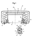
- FIG 1 is an airbag module housed in the steering wheel of a vehicle 10 shown, which has a cup-shaped outer housing 12, the back by a Generator bracket 14 or a similar part is closed.
- the gas bag module includes a gas bag 16 and a cylindrical gas generator 18 a central axis 20 housed. Between gas bag 16 and gas generator 18 sits a cup-shaped diffuser 22 which is screwed to the generator mounting plate 14.
- the gas generator has a radial, circumferential flange 24 on its An elastic member 26 in the form of an annular top along the top Flange 24 extending, closed circumferential hollow profile.
- the The hollow profile is circular in cross-section.
- the gas generator 18 is mounted in a vibration-decoupled manner in the module 10.
- the elastic elements 26, 28 are compressed in the radial direction, by pressing a shoulder 30 of the diffuser 22 on the element 26 and thus the two elements 26, 28 together with the flange 24 between them and the holding plate 14 is stuck.
- the elements 26, 28 are consequently installed so that their annular Longitudinal axis A running parallel to flange 24 is perpendicular to axis 20.
- each element 26, 28 with the radial outside of its peripheral wall on a first circumferential section 40 and 42 on the flange 24 and on a opposite section 44 or 46 on the diffuser 22 or the holding plate 14 is applied.
- the elements 26, 28 through the diffuser 22 and Generator holding plate 14 pressed towards each other to between the Clamp the holding flange 24.
- the embodiment according to FIG. 2 differs from that according to FIG. 1 only through the formation of the elastic element, whereby according to FIG only a single elastic element 50 is provided, which is different from the Top of the retaining flange 24 and along the outer peripheral edge to Underside of the holding flange 24 extends.
- the elastic element 50 which is also ring-shaped circumferential and in Cross section has a closed hollow profile, one directed radially outwards Indentation.
- the gas generator 18 is switched on the elastic element 50 by means of clamping the retaining flange 24 between Sections of the elastic element 50 vibration decoupled in the module stored.
- the diffuser 22 presses the elastic element 50 down towards the generator mounting plate 14, which is like the diffuser 22 a holding part for the gas generator 18 and the elastic element or elements 50 or 26, 28 forms.
- each elastic element 26, 28, 50 does not have only the function of storing the gas generator 18 in a vibration-decoupled manner, but also the function of an outflow of gas along the holding flange 24, through the gap between the holding flange 24 and the diffuser 22 and the To prevent the holding flange 24 and the holding plate 14.
- This gap is namely sealed gas-tight by the elastic elements 26, 28, 50, so that the gas can not flow out of the rear of the module 10, but only via the Diffuser 22 will get into the interior of the gas bag 16.
- Figures 3a to 3c are still different variants of the elastic Elementes shown, in which the elastic element has a higher stability received by additional means.
- the elastic element 70 is inside foamed, the foam being provided with the reference number 72.
- the elastic element 80 according to FIG. 3b has two bowl-shaped cross sections, circumferential elastic support elements 82 which are used in the manufacture of the elastic Elements 80 were inserted.
- elastic element 90 on its peripheral wall openings in the form of slots, through which are inserted from the outside radially strip-shaped support elements 92. The slots are labeled 94.
- the elastic elements are made of one Made of elastomer.
Landscapes
- Engineering & Computer Science (AREA)
- Mechanical Engineering (AREA)
- Air Bags (AREA)
Abstract
Description
Die Erfindung betrifft ein Gasssackmodul, mit einem Gasgenerator, der im Modul mittels wenigstens eines elastischen Elements schwingungsentkoppelt gelagert ist.The invention relates to an airbag module with a gas generator, which in Vibration decoupled module by means of at least one elastic element is stored.
Solche Gassackmodule werden bislang ausschließlich in Lenkrädern vorgesehen und bieten den Vorteil, daß der relativ schwere Gasgenerator schwingungsentkoppelt vom Rest des Moduls gelagert ist und damit die Vibrationsneigung des Lenkrads abnimmt. Der Gasgenerator kann auch als sogenannter Schwingungstilger ausgelegt sein. Das Entkoppeln des Gasgenerators erfolgt mittels des oder der elastischen Elemente, über die der Gasgenerator im Modul gehaltert ist. Das elastische Element muß hohen Anforderungen genügen, zum Beispiel über den Betriebstemperaturbereich von -40° bis +80° möglichst gleichbleibend elastisch und darüber hinaus alterungsbeständig sein. Ferner muß die Befestigung am Gasgenerator sehr sicher sein, wobei zum Beispiel Aufvulkanisieren angedacht wird. Such gas bag modules have so far been used exclusively in steering wheels provided and have the advantage that the relatively heavy gas generator is vibration decoupled from the rest of the module and thus the Vibration tendency of the steering wheel decreases. The gas generator can also be used as so-called vibration absorber can be designed. Decoupling the gas generator takes place by means of the elastic element or elements via which the gas generator in the Module is held. The elastic element must meet high requirements, for example over the operating temperature range from -40 ° to + 80 ° if possible be consistently elastic and also be resistant to aging. Furthermore, must the attachment to the gas generator be very secure, for example Vulcanization is being considered.
Die Erfindung schafft ein Gassackmodul mit einem einfach aufgebauten, den oben genannten Anforderungen entsprechenden elastischen Element. Beim Gassackmodul nach der Erfindung ist das elastische Element ein im Querschnitt geschlossenes Hohlprofil mit einer Umfangswand, deren radiale Außenseite einerseits am Gasgenerator und andererseits an einem modulseitigen Halteteil anliegt. Ein Hohlprofil hat den Vorteil, daß es sich aufgrund seiner Geometrie Konturen sehr gut anpaßt, denn es kann gegenüber einem O-Ring oder einem Gummipuffer auch nach innen stark nachgeben, wodurch seine Elastizität gesteigert werden kann.The invention creates an airbag module with a simply constructed, the above-mentioned requirements corresponding elastic element. At the Airbag module according to the invention, the elastic element is a in cross section closed hollow profile with a peripheral wall, the radial outside on the one hand on the gas generator and on the other hand on a module-side holding part is applied. A hollow profile has the advantage that it is due to its geometry Adapts contours very well, because it can be compared to an O-ring or one Rubber bumps also give way to the inside, reducing its elasticity can be increased.
Vorzugsweise umschließt das elastische Element den Gasgenerator vollständig und kann darüber hinaus einen Spalt zwischen einem Halteteil am Modul und dem Gasgenerator abdichten, so daß das elastische Element eine Doppelfunktion innehat (entkoppelte Lagerung am Halteteil und Abdichtung). Durch die Abdichtung soll gewährleistet sein, daß kein Gas im Bereich der Halterung des Gasgenerators aus dem Modul heraustreten kann.The elastic element preferably completely surrounds the gas generator and can also create a gap between a holding part on the module and the Seal the gas generator so that the elastic element has a double function held (decoupled storage on the holding part and sealing). Through the Sealing should be ensured that no gas in the area of the bracket Gas generator can step out of the module.
Das elastische Element hat gemäß einer bevorzugten Ausführungsform eine geschlossene Ringform, was die Dichtigkeit erhöht.According to a preferred embodiment, the elastic element has a closed ring shape, which increases the tightness.
Innenseitig kann das elastische Element darüber hinaus ausgeschäumt sein, um die Stabilität desselben zu erhöhen. Eine Stabilitätserhöhung kann aber auch dadurch erfolgen, daß wenigstens ein elastisches Stützelement im elastischen Element untergebracht ist. Dieses Stützelement wird vorzugsweise in das elastische Element eingelegt (zum Beispiel bei seiner Fertigung) oder in Öffnungen im elastischen Element eingeschoben.On the inside, the elastic element can also be foamed to to increase its stability. An increase in stability can also in that at least one elastic support element in the elastic Element is housed. This support element is preferably in the elastic element inserted (for example during its manufacture) or in Openings inserted in the elastic element.
Eine Ausführungsform sieht vor, daß das elastische Element im nicht verbauten Zustand einen kreisrunden Querschnitt einnimmt, also ein sehr einfach zu fertigendes Hohlprofil ist.One embodiment provides that the elastic element is not installed state takes a circular cross-section, so a very simple hollow profile to be manufactured.
Eine erste Ausführungsform der Erfindung schlägt vor, daß der Gasgenerator einen radialen Halteflansch hat, an dessen Ober- und dessen Unterseite jeweils ein elastisches Element anliegt. Die Elemente werden durch Halteteile aufeinander zu gedrückt, um zwischen sich den Halteflansch zu klemmen. Ein Vorteil hierbei ist die einfache Montage und die einfach zu fertigende Ausführung der elastischen Elemente.A first embodiment of the invention proposes that the gas generator has a radial retaining flange on the top and bottom of each rests on the elastic element. The elements are brought together by holding parts pressed to clamp the retaining flange between them. One advantage here is the simple assembly and the easy-to-manufacture version of the elastic Elements.
Eine zweite Ausführung sieht vor, daß nur ein einziges elastisches Element vorgesehen ist, wobei sich dieses von der Oberseite des Halteflansches des Gasgenerators und am Umfangsrand entlang bis zu der Unterseite des Halteflansches erstreckt. Durch Halteteile wird das elastische Element gegen die Ober- und die Unterseite gedrückt, um den Halteflansch zwischen sich zu klemmen. Hauptvorteil dieser Ausführungsform ist, daß nur ein einziges elastisches Element vorgesehen ist, das sich auch radial außerhalb des Umfangsrandes erstreckt.A second embodiment provides that only a single elastic element is provided, which is from the top of the retaining flange Gas generator and along the peripheral edge to the bottom of the Holding flange extends. By holding parts, the elastic element against the Top and bottom pressed to keep the retaining flange between them terminals. The main advantage of this embodiment is that only one elastic element is provided, which is also radially outside of Extends peripheral edge.
Bevorzugt ist eines der Halteteile, die zum Klemmen des elastischen Elements führen, ein den Gasgenerator umgebender, topfförmiger Diffusor, also ein ohnehin vorgesehenes Teil, das mit der Klemmung des elastischen Elements oder der elastischen Elemente eine weitere Funktion bekommt.Preferred is one of the holding parts for clamping the elastic element lead, a cup-shaped diffuser surrounding the gas generator anyway provided part that with the clamping of the elastic element or the elastic elements get another function.
Beim erfindungsgemäßen Gassackmodul wird das Hohlprofil quer zu seiner Längserstreckung durch den Gasgenerator belastet, das heißt im Querschnitt gesehen quer zu seiner Längserstreckung. Im Stand der Technik gibt es zwar elastische Elemente in Form von kurzen Buchsen, diese Buchsen werden aber in axialer Richtung belastet, so daß ihre Nachgiebigkeit begrenzt ist. Darüber hinaus bilden diese Buchsen nur Punktauflagen und können keine Abdichtung gewährleisten.In the gas bag module according to the invention, the hollow profile is transverse to it Longitudinal extension loaded by the gas generator, that is, in cross section seen across its length. There is in the state of the art elastic elements in the form of short bushings, but these bushings are made in axially loaded, so that their flexibility is limited. Furthermore these bushings only form point supports and cannot seal guarantee.
Weitere Merkmale und Vorteile der Erfindung ergeben sich aus der nachfolgenden Beschreibung und aus den nachfolgenden Zeichnungen, auf die Bezug genommen wird. In den Zeichnungen zeigen:
- Figur 1 eine Querschnittsansicht eines erfindungsgemäßen Gasgenerators gemäß einer ersten Ausführungsform,
- Figur 2 eine Querschnittsansicht eines erfindungsgemäßen Gasgenerators gemäß einer zweiten Ausführungsform, und
- Figuren 3a bis c Querschnittsansichten verschiedener elastischer Elemente.
- FIG. 1 shows a cross-sectional view of a gas generator according to the invention in accordance with a first embodiment,
- FIG. 2 shows a cross-sectional view of a gas generator according to the invention in accordance with a second embodiment, and
- Figures 3a to c cross-sectional views of various elastic elements.
In Figur 1 ist ein im Lenkrad eines Fahrzeugs untergebrachtes Gassackmodul
10 dargestellt, das ein topfförmiges Außengehäuse 12 hat, das rückseitig durch ein
Generatorhalteblech 14 oder ein ähnliches Teil geschlossen ist. Im Inneren des
Gassackmoduls sind ein Gassack 16 sowie ein zylindrischer Gasgenerator 18 mit
einer Mittelachse 20 untergebracht. Zwischen Gassack 16 und Gasgenerator 18
sitzt ein topfförmiger Diffusor 22, der am Generatorhalteblech 14 verschraubt ist.
Der Gasgenerator hat einen radialen, umlaufenden Flansch 24, an dessen
Oberseite ein elastisches Element 26 in Form eines ringförmig entlang des
Flansches 24 verlaufenden, im Umfang geschlossenen Hohlprofils anliegt. Das
Hohlprofil ist im Querschnitt kreisringförmig ausgeführt. Ein zweites elastisches
Element 28, das die gleiche Geometrie wie das elastische Element 26 aufweist,
liegt an der Unterseite des Flansches 24 an. Über die elastischen Elemente 26, 28
wird der Gasgenerator 18 schwingungsentkoppelt im Modul 10 gelagert. Die
elastischen Elemente 26, 28 werden in radialer Richtung zusammengedrückt,
indem ein Absatz 30 des Diffusors 22 auf das Element 26 drückt und damit die
beiden Elemente 26, 28 samt des Flansches 24 zwischen sich und dem Halteblech
14 klemmt. Die Elemente 26, 28 sind folglich so eingebaut, daß ihre ringförmig
parallel zum Flansch 24 verlaufende Längsachse A senkrecht zur Achse 20 steht.In Figure 1 is an airbag module housed in the steering wheel of a
Dem vergrößerten Ausschnitt von Figur 1 ist zu entnehmen, daß jedes Element
26, 28 mit der radialen Außenseite seiner Umfangswand an einem ersten
umlaufenden Abschnitt 40 bzw. 42 am Flansch 24 und an einem
entgegengesetzten Abschnitt 44 bzw. 46 am Diffusor 22 bzw. dem Halteblech 14
anliegt. Das bedeutet, die Elemente 26, 28 sind im eingebauten Zustand quer zu
ihrer Längserstreckung belastet und vorgespannt und werden auch im Betrieb quer
zur Längserstreckung, das heißt radial belastet. Bei der Ausführungsform nach
Figur 1 werden die Elemente 26, 28 durch den Diffusor 22 und das
Generatorhalteblech 14 aufeinander zu gedrückt, um zwischen sich den
Halteflansch 24 zu klemmen.The enlarged section of Figure 1 shows that each
Die Ausführungsform nach Figur 2 unterscheidet sich von der nach Figur 1
lediglich durch die Ausbildung des elastischen Elements, wobei gemäß Figur 2
nur ein einziges elastisches Element 50 vorgesehen ist, welches sich von der
Oberseite des Halteflansches 24 und am äußeren Umfangsrand entlang bis zur
Unterseite des Halteflansches 24 erstreckt. Im Bereich des Umfangsrandes erhält
das elastische Element 50, das ebenfalls ringförmig umlaufend ist und im
Querschnitt ein geschlossenes Hohlprofil hat, eine nach radial außen gerichtete
Einbuchtung. Auch bei dieser Ausführungsform wird der Gasgenerator 18 durch
das elastische Element 50 mittels Klemmen des Halteflansches 24 zwischen
Abschnitten des elastischen Elementes 50 schwingungsentkoppelt im Modul
gelagert. Hierzu drückt, wie bei Figur 1, der Diffusor 22 das elastische Element 50
nach unten in Richtung zum Generatorhalteblech 14, das ebenso wie der Diffusor
22 ein Halteteil für den Gasgenerator 18 und das bzw. die elastischen Elemente 50
bzw. 26, 28 bildet.The embodiment according to FIG. 2 differs from that according to FIG. 1
only through the formation of the elastic element, whereby according to FIG
only a single
Bei beiden Ausführungsformen hat jedes elastische Element 26, 28, 50 nicht
nur die Funktion, den Gasgenerator 18 schwingungsentkoppelt zu lagern, sondern
auch noch die Funktion, ein Ausströmen von Gas entlang des Halteflansches 24,
durch den Spalt zwischen dem Halteflansch 24 und dem Diffusor 22 sowie dem
Halteflansch 24 und dem Halteblech 14 zu verhindern. Dieser Spalt wird nämlich
durch die elastischen Elemente 26, 28, 50 gasdicht verschlossen, so daß das Gas
nicht rückseitig aus dem Modul 10 herausströmen kann, sondern nur über den
Diffusor 22 in das Innere des Gassacks 16 gelangen wird.In both embodiments, each
In den Figuren 3a bis 3c sind noch verschiedene Varianten des elastischen Elementes dargestellt, bei denen das elastische Element eine höhere Stabilität durch zusätzliche Mittel erhält.In Figures 3a to 3c are still different variants of the elastic Elementes shown, in which the elastic element has a higher stability received by additional means.
Bei der Ausführung nach Figur 3a ist das elastische Element 70 im Inneren
ausgeschäumt, wobei der Schaum mit dem Bezugszeichen 72 versehen ist. Das
elastische Element 80 gemäß Figur 3b hat zwei im Querschnitt schalenförmige,
umlaufende elastische Stützelemente 82, die bei der Herstellung des elastischen
Elements 80 eingelegt wurden. Bei der Ausführungsform nach Figur 3c hat das
elastische Element 90 an seiner Umfangswand Öffnungen in Form von Schlitzen,
durch die von radial außen streifenförmige Stützelemente 92 eingeschoben sind.
Die Schlitze sind mit 94 bezeichnet.In the embodiment according to FIG. 3a, the
Bei allen Ausführungsformen sind die elastischen Elemente aus einem Elastomer hergestellt.In all embodiments, the elastic elements are made of one Made of elastomer.
Claims (12)
dadurch gekennzeichnet, daß
das elastische Element (26, 28; 50; 70; 80; 90) ein im Querschnitt geschlossenes Hohlprofil mit einer Umfangswand ist, deren radiale Außenseite einerseits am Gasgenerator (18) und andererseits an einem modulseitigen Halteteil (14, 22) anliegt.Airbag module, with a gas generator (18) which is mounted in the module (10) by means of at least one elastic element (26, 28; 50; 70; 80; 90),
characterized in that
the elastic element (26, 28; 50; 70; 80; 90) is a hollow profile closed in cross section with a peripheral wall, the radial outside of which rests on the one hand on the gas generator (18) and on the other hand on a module-side holding part (14, 22).
Applications Claiming Priority (2)
| Application Number | Priority Date | Filing Date | Title |
|---|---|---|---|
| DE20108594U | 2001-05-22 | ||
| DE20108594U DE20108594U1 (en) | 2001-05-22 | 2001-05-22 | Airbag module |
Publications (3)
| Publication Number | Publication Date |
|---|---|
| EP1260415A2 true EP1260415A2 (en) | 2002-11-27 |
| EP1260415A3 EP1260415A3 (en) | 2003-08-13 |
| EP1260415B1 EP1260415B1 (en) | 2004-10-27 |
Family
ID=7957206
Family Applications (1)
| Application Number | Title | Priority Date | Filing Date |
|---|---|---|---|
| EP02010265A Expired - Lifetime EP1260415B1 (en) | 2001-05-22 | 2002-05-17 | Airbag module |
Country Status (4)
| Country | Link |
|---|---|
| US (1) | US6814369B2 (en) |
| EP (1) | EP1260415B1 (en) |
| DE (2) | DE20108594U1 (en) |
| ES (1) | ES2231610T3 (en) |
Families Citing this family (15)
| Publication number | Priority date | Publication date | Assignee | Title |
|---|---|---|---|---|
| DE10215330C1 (en) | 2002-04-03 | 2003-04-24 | Takata Petri Ag | Resiliently-mounted gas generator, for steering wheel air bag module, comprises upward and downward slanting holders |
| DE20304551U1 (en) | 2003-03-21 | 2003-07-31 | TRW Automotive Safety Systems GmbH, 63743 Aschaffenburg | Airbag module for a motor vehicle steering wheel with an oscillating gas generator |
| FR2855122B1 (en) * | 2003-05-22 | 2005-08-12 | Aerazur | SEALING DEVICE FOR THE INTERFACE BETWEEN AN INFLATABLE SAFETY BAG AND A GAS GENERATOR |
| US7144034B2 (en) * | 2004-02-18 | 2006-12-05 | Autoliv Asp, Inc. | Vibration damper gasket |
| US20060061068A1 (en) * | 2004-09-20 | 2006-03-23 | Krista Nash | Dab vibration damper |
| DE102004008043A1 (en) * | 2004-02-19 | 2005-09-15 | Autoliv Development Ab | Airbag module with vibration damped gas generator has vibration damping holder with head acting as stop for gas generator for lateral movement of gas generator in plane of flange sections |
| WO2005080145A1 (en) * | 2004-02-21 | 2005-09-01 | Autoliv Development Ab | Airbag module comprising a clipped-in diffuser |
| DE102004010144B4 (en) * | 2004-02-27 | 2006-03-23 | Zf Friedrichshafen Ag | Arrangement for fixing the gas generator of an airbag unit |
| DE202006000843U1 (en) * | 2006-01-13 | 2006-04-06 | Takata-Petri Ag | Airbag fastening in an airbag module by means of a clamping connection |
| US7494150B2 (en) * | 2006-04-05 | 2009-02-24 | Arc Automotive, Inc. | Air bag inflator vibration damper |
| DE102007049234B4 (en) * | 2007-10-10 | 2014-12-04 | TAKATA Aktiengesellschaft | Airbag module for a motor vehicle |
| DE102008026795A1 (en) * | 2008-06-02 | 2009-12-10 | Takata-Petri Ag | airbag module |
| DE102010052782A1 (en) * | 2010-11-30 | 2012-05-31 | Trw Automotive Gmbh | Vehicle occupant restraint system for vehicle, comprises gas generator and gas bag, which is connected with gas generator, where gas generator comprises fastening extension |
| US9242614B2 (en) * | 2014-03-07 | 2016-01-26 | Autoliv Asp, Inc. | Airbag systems with energy-absorbing components |
| DE202014008432U1 (en) * | 2014-10-23 | 2016-01-26 | Trw Automotive Safety Systems Gmbh | Device for vibratory mounting of a gas generator in an airbag module |
Family Cites Families (17)
| Publication number | Priority date | Publication date | Assignee | Title |
|---|---|---|---|---|
| US3810446A (en) * | 1973-07-18 | 1974-05-14 | R Kightlinger | Animal food bowl and cover therefor |
| US4576118A (en) * | 1985-03-04 | 1986-03-18 | Meadows Winston R | Pet feeding bowl |
| DE3530853A1 (en) * | 1985-08-29 | 1987-03-05 | Guenter Andersson | FOOD BOWL SET |
| US4949678A (en) * | 1989-11-13 | 1990-08-21 | Demko Albert J | Disposable pet feeding dish |
| US5346710A (en) * | 1990-06-22 | 1994-09-13 | Contagious Concepts | Animal feeding system and method therefor |
| US5388858A (en) * | 1991-02-25 | 1995-02-14 | Trw, Inc. | Air bag module structure and method of assembly |
| US5580080A (en) * | 1995-09-20 | 1996-12-03 | Morton International, Inc. | Cushion attachment for airbags |
| DE29519700U1 (en) * | 1995-12-12 | 1996-04-11 | Trw Occupant Restraint Systems Gmbh, 73551 Alfdorf | Vehicle steering wheel with an integrated vehicle occupant restraint system |
| US5925390A (en) * | 1996-04-02 | 1999-07-20 | Kornacki; Joan M. | Cat food dispensing system and method of manufacture |
| DE19840998B4 (en) * | 1998-09-08 | 2008-01-24 | Takata-Petri Ag | Airbag arrangement in vehicles |
| DE29816925U1 (en) | 1998-09-16 | 1998-11-26 | Petri Ag, 63743 Aschaffenburg | Steering wheel with airbag module |
| DE29816923U1 (en) * | 1998-09-16 | 1998-11-26 | Petri Ag, 63743 Aschaffenburg | Steering wheel with airbag module |
| DE19858691B4 (en) * | 1998-12-18 | 2010-01-07 | Delphi Automotive Systems Deutschland Gmbh | Air bag module for motor vehicles |
| DE29902033U1 (en) * | 1999-02-05 | 1999-04-08 | TRW Automotive Safety Systems GmbH, 63743 Aschaffenburg | Airbag module as a vibration damper |
| DE19955426B4 (en) * | 1999-11-18 | 2005-11-10 | Carl Freudenberg Kg | Gas generator for an airbag |
| DE10156424B4 (en) * | 2000-11-27 | 2016-11-24 | Autoliv Development Ab | Air bag module for motor vehicles |
| US20030192480A1 (en) * | 2002-04-16 | 2003-10-16 | Harold Bennett | Feeding stand for pet food package |
-
2001
- 2001-05-22 DE DE20108594U patent/DE20108594U1/en not_active Expired - Lifetime
-
2002
- 2002-05-17 EP EP02010265A patent/EP1260415B1/en not_active Expired - Lifetime
- 2002-05-17 ES ES02010265T patent/ES2231610T3/en not_active Expired - Lifetime
- 2002-05-17 DE DE50201382T patent/DE50201382D1/en not_active Expired - Lifetime
- 2002-05-21 US US10/152,892 patent/US6814369B2/en not_active Expired - Fee Related
Non-Patent Citations (1)
| Title |
|---|
| None |
Also Published As
| Publication number | Publication date |
|---|---|
| ES2231610T3 (en) | 2005-05-16 |
| US6814369B2 (en) | 2004-11-09 |
| DE50201382D1 (en) | 2004-12-02 |
| DE20108594U1 (en) | 2001-09-27 |
| US20020175500A1 (en) | 2002-11-28 |
| EP1260415B1 (en) | 2004-10-27 |
| EP1260415A3 (en) | 2003-08-13 |
Similar Documents
| Publication | Publication Date | Title |
|---|---|---|
| EP1260415B1 (en) | Airbag module | |
| EP1020332B1 (en) | Airbag module for vehicles | |
| DE10027240B4 (en) | Air bag module for motor vehicles | |
| EP1113948B2 (en) | Steering with airbag module | |
| EP0423435A1 (en) | Air filter with radial sealing filter insert | |
| EP2364763B1 (en) | Filter element and filter device | |
| DE29902033U1 (en) | Airbag module as a vibration damper | |
| DE19755549C2 (en) | Suspension strut for vehicles | |
| DE10156424B4 (en) | Air bag module for motor vehicles | |
| WO2016062379A1 (en) | Device for securing a gas generator in an airbag module in an oscillating manner | |
| WO2022194544A1 (en) | Filter element and filter system | |
| DE19908915B4 (en) | Vibration damper for a steering wheel with an airbag | |
| EP2546504B2 (en) | Internal combustion engine | |
| DE20105434U1 (en) | Airbag module | |
| DE10215330C1 (en) | Resiliently-mounted gas generator, for steering wheel air bag module, comprises upward and downward slanting holders | |
| EP1324900B1 (en) | Housing for motor vehicle airbag | |
| DE102007049234B4 (en) | Airbag module for a motor vehicle | |
| DE102017119335A1 (en) | GASSACK MODULE FOR A VEHICLE WHEEL | |
| DE10318613B3 (en) | Pressure pulsation damping device for automobile braking system using carrier element inserted in hydraulic braking circuit provided with elastomer body incorporating at least one damping chamber | |
| DE20317961U1 (en) | Airbag module | |
| EP1238869A1 (en) | Gas generator for an airbag on a steering wheel of a motor vehicle | |
| EP1362751A1 (en) | Airbag module with resilient support of the gas generator | |
| EP1612112B1 (en) | Air bag module with yieldably mounted gas generator | |
| EP0429084B1 (en) | Elastic support for vehicle cabins | |
| DE20104044U1 (en) | Airbag module |
Legal Events
| Date | Code | Title | Description |
|---|---|---|---|
| PUAI | Public reference made under article 153(3) epc to a published international application that has entered the european phase |
Free format text: ORIGINAL CODE: 0009012 |
|
| AK | Designated contracting states |
Kind code of ref document: A2 Designated state(s): AT BE CH CY DE DK ES FI FR GB GR IE IT LI LU MC NL PT SE TR |
|
| AX | Request for extension of the european patent |
Free format text: AL;LT;LV;MK;RO;SI |
|
| PUAL | Search report despatched |
Free format text: ORIGINAL CODE: 0009013 |
|
| AK | Designated contracting states |
Designated state(s): AT BE CH CY DE DK ES FI FR GB GR IE IT LI LU MC NL PT SE TR |
|
| AX | Request for extension of the european patent |
Extension state: AL LT LV MK RO SI |
|
| 17P | Request for examination filed |
Effective date: 20040129 |
|
| GRAP | Despatch of communication of intention to grant a patent |
Free format text: ORIGINAL CODE: EPIDOSNIGR1 |
|
| AKX | Designation fees paid |
Designated state(s): DE ES FR GB IT |
|
| RAP1 | Party data changed (applicant data changed or rights of an application transferred) |
Owner name: TRW AUTOMOTIVE SAFETY SYSTEMS GMBH |
|
| GRAS | Grant fee paid |
Free format text: ORIGINAL CODE: EPIDOSNIGR3 |
|
| GRAA | (expected) grant |
Free format text: ORIGINAL CODE: 0009210 |
|
| AK | Designated contracting states |
Kind code of ref document: B1 Designated state(s): DE ES FR GB IT |
|
| REG | Reference to a national code |
Ref country code: GB Ref legal event code: FG4D Free format text: NOT ENGLISH |
|
| REG | Reference to a national code |
Ref country code: IE Ref legal event code: FG4D Free format text: GERMAN |
|
| REF | Corresponds to: |
Ref document number: 50201382 Country of ref document: DE Date of ref document: 20041202 Kind code of ref document: P |
|
| GBT | Gb: translation of ep patent filed (gb section 77(6)(a)/1977) |
Effective date: 20050113 |
|
| REG | Reference to a national code |
Ref country code: ES Ref legal event code: FG2A Ref document number: 2231610 Country of ref document: ES Kind code of ref document: T3 |
|
| PGFP | Annual fee paid to national office [announced via postgrant information from national office to epo] |
Ref country code: FR Payment date: 20050517 Year of fee payment: 4 |
|
| REG | Reference to a national code |
Ref country code: IE Ref legal event code: FD4D |
|
| PLBE | No opposition filed within time limit |
Free format text: ORIGINAL CODE: 0009261 |
|
| STAA | Information on the status of an ep patent application or granted ep patent |
Free format text: STATUS: NO OPPOSITION FILED WITHIN TIME LIMIT |
|
| ET | Fr: translation filed | ||
| 26N | No opposition filed |
Effective date: 20050728 |
|
| PG25 | Lapsed in a contracting state [announced via postgrant information from national office to epo] |
Ref country code: GB Free format text: LAPSE BECAUSE OF NON-PAYMENT OF DUE FEES Effective date: 20060517 |
|
| PGFP | Annual fee paid to national office [announced via postgrant information from national office to epo] |
Ref country code: ES Payment date: 20060518 Year of fee payment: 5 |
|
| PGFP | Annual fee paid to national office [announced via postgrant information from national office to epo] |
Ref country code: IT Payment date: 20060531 Year of fee payment: 5 |
|
| GBPC | Gb: european patent ceased through non-payment of renewal fee |
Effective date: 20060517 |
|
| REG | Reference to a national code |
Ref country code: FR Ref legal event code: ST Effective date: 20080131 |
|
| PG25 | Lapsed in a contracting state [announced via postgrant information from national office to epo] |
Ref country code: FR Free format text: LAPSE BECAUSE OF NON-PAYMENT OF DUE FEES Effective date: 20070531 |
|
| REG | Reference to a national code |
Ref country code: ES Ref legal event code: FD2A Effective date: 20070518 |
|
| PG25 | Lapsed in a contracting state [announced via postgrant information from national office to epo] |
Ref country code: FR Free format text: LAPSE BECAUSE OF NON-PAYMENT OF DUE FEES Effective date: 20060531 |
|
| PG25 | Lapsed in a contracting state [announced via postgrant information from national office to epo] |
Ref country code: ES Free format text: LAPSE BECAUSE OF NON-PAYMENT OF DUE FEES Effective date: 20070518 |
|
| PG25 | Lapsed in a contracting state [announced via postgrant information from national office to epo] |
Ref country code: IT Free format text: LAPSE BECAUSE OF NON-PAYMENT OF DUE FEES Effective date: 20070517 |
|
| PGFP | Annual fee paid to national office [announced via postgrant information from national office to epo] |
Ref country code: DE Payment date: 20150531 Year of fee payment: 14 |
|
| REG | Reference to a national code |
Ref country code: DE Ref legal event code: R119 Ref document number: 50201382 Country of ref document: DE |
|
| PG25 | Lapsed in a contracting state [announced via postgrant information from national office to epo] |
Ref country code: DE Free format text: LAPSE BECAUSE OF NON-PAYMENT OF DUE FEES Effective date: 20161201 |