EP1260263A1 - Filter assembly - Google Patents
Filter assembly Download PDFInfo
- Publication number
- EP1260263A1 EP1260263A1 EP02004588A EP02004588A EP1260263A1 EP 1260263 A1 EP1260263 A1 EP 1260263A1 EP 02004588 A EP02004588 A EP 02004588A EP 02004588 A EP02004588 A EP 02004588A EP 1260263 A1 EP1260263 A1 EP 1260263A1
- Authority
- EP
- European Patent Office
- Prior art keywords
- filter
- cover
- pleated filter
- arrangement according
- filter arrangement
- Prior art date
- Legal status (The legal status is an assumption and is not a legal conclusion. Google has not performed a legal analysis and makes no representation as to the accuracy of the status listed.)
- Granted
Links
- 230000006378 damage Effects 0.000 claims abstract description 3
- 238000011144 upstream manufacturing Methods 0.000 claims description 19
- 239000000463 material Substances 0.000 claims description 11
- 238000007789 sealing Methods 0.000 claims description 7
- 238000004519 manufacturing process Methods 0.000 description 3
- 238000010276 construction Methods 0.000 description 2
- 230000001066 destructive effect Effects 0.000 description 2
- 230000000694 effects Effects 0.000 description 1
- 238000005265 energy consumption Methods 0.000 description 1
- 239000006260 foam Substances 0.000 description 1
- 230000009760 functional impairment Effects 0.000 description 1
- 239000007769 metal material Substances 0.000 description 1
- 239000004745 nonwoven fabric Substances 0.000 description 1
- 239000002861 polymer material Substances 0.000 description 1
- 238000004064 recycling Methods 0.000 description 1
Images


Classifications
-
- B—PERFORMING OPERATIONS; TRANSPORTING
- B01—PHYSICAL OR CHEMICAL PROCESSES OR APPARATUS IN GENERAL
- B01D—SEPARATION
- B01D35/00—Filtering devices having features not specifically covered by groups B01D24/00 - B01D33/00, or for applications not specifically covered by groups B01D24/00 - B01D33/00; Auxiliary devices for filtration; Filter housing constructions
- B01D35/30—Filter housing constructions
-
- B—PERFORMING OPERATIONS; TRANSPORTING
- B01—PHYSICAL OR CHEMICAL PROCESSES OR APPARATUS IN GENERAL
- B01D—SEPARATION
- B01D46/00—Filters or filtering processes specially modified for separating dispersed particles from gases or vapours
- B01D46/52—Particle separators, e.g. dust precipitators, using filters embodying folded corrugated or wound sheet material
- B01D46/521—Particle separators, e.g. dust precipitators, using filters embodying folded corrugated or wound sheet material using folded, pleated material
-
- B—PERFORMING OPERATIONS; TRANSPORTING
- B01—PHYSICAL OR CHEMICAL PROCESSES OR APPARATUS IN GENERAL
- B01D—SEPARATION
- B01D46/00—Filters or filtering processes specially modified for separating dispersed particles from gases or vapours
- B01D46/0002—Casings; Housings; Frame constructions
- B01D46/0005—Mounting of filtering elements within casings, housings or frames
- B01D46/0006—Filter elements or cartridges installed in a drawer-like manner
-
- B—PERFORMING OPERATIONS; TRANSPORTING
- B01—PHYSICAL OR CHEMICAL PROCESSES OR APPARATUS IN GENERAL
- B01D—SEPARATION
- B01D46/00—Filters or filtering processes specially modified for separating dispersed particles from gases or vapours
- B01D46/10—Particle separators, e.g. dust precipitators, using filter plates, sheets or pads having plane surfaces
-
- B—PERFORMING OPERATIONS; TRANSPORTING
- B01—PHYSICAL OR CHEMICAL PROCESSES OR APPARATUS IN GENERAL
- B01D—SEPARATION
- B01D46/00—Filters or filtering processes specially modified for separating dispersed particles from gases or vapours
- B01D46/88—Replacing filter elements
-
- B—PERFORMING OPERATIONS; TRANSPORTING
- B60—VEHICLES IN GENERAL
- B60H—ARRANGEMENTS OF HEATING, COOLING, VENTILATING OR OTHER AIR-TREATING DEVICES SPECIALLY ADAPTED FOR PASSENGER OR GOODS SPACES OF VEHICLES
- B60H3/00—Other air-treating devices
- B60H3/06—Filtering
- B60H3/0608—Filter arrangements in the air stream
- B60H3/0616—Filter arrangements in the air stream with provisions for replacing the filter element
-
- F—MECHANICAL ENGINEERING; LIGHTING; HEATING; WEAPONS; BLASTING
- F24—HEATING; RANGES; VENTILATING
- F24F—AIR-CONDITIONING; AIR-HUMIDIFICATION; VENTILATION; USE OF AIR CURRENTS FOR SCREENING
- F24F13/00—Details common to, or for air-conditioning, air-humidification, ventilation or use of air currents for screening
- F24F13/28—Arrangement or mounting of filters
-
- B—PERFORMING OPERATIONS; TRANSPORTING
- B60—VEHICLES IN GENERAL
- B60H—ARRANGEMENTS OF HEATING, COOLING, VENTILATING OR OTHER AIR-TREATING DEVICES SPECIALLY ADAPTED FOR PASSENGER OR GOODS SPACES OF VEHICLES
- B60H3/00—Other air-treating devices
- B60H3/06—Filtering
- B60H3/0608—Filter arrangements in the air stream
- B60H2003/065—Details for holding filter elements in position
-
- F—MECHANICAL ENGINEERING; LIGHTING; HEATING; WEAPONS; BLASTING
- F02—COMBUSTION ENGINES; HOT-GAS OR COMBUSTION-PRODUCT ENGINE PLANTS
- F02M—SUPPLYING COMBUSTION ENGINES IN GENERAL WITH COMBUSTIBLE MIXTURES OR CONSTITUENTS THEREOF
- F02M35/00—Combustion-air cleaners, air intakes, intake silencers, or induction systems specially adapted for, or arranged on, internal-combustion engines
- F02M35/02—Air cleaners
- F02M35/024—Air cleaners using filters, e.g. moistened
Definitions
- the invention relates to a filter arrangement comprising a pleated filter and a cover of a filter housing.
- Such a filter arrangement is known.
- the pleated filter is first assembled as a single part in the filter housing, the mounting opening of the filter housing then being closed by the cover.
- the lid and the pleated filter are sealed against each other by means of a separately produced seal. It should be noted, however, that the assembly of such a filter arrangement is unsatisfactory.
- the spatial assignment and / or sealing of the pleated filter and cover to one another essentially depends on the skills and reliability of the fitter, with incorrectly installed pleated filters and / or covers often leading to undesired leaks and / or to a flow short circuit between the connection and outflow side of the pleated filter.
- the assembly work on the belt and if the filter housing is difficult to access is considerable.
- the invention has for its object a filter arrangement of the beginning to develop the type mentioned in such a way that it is simple and low in parts Has structure and is therefore easy and inexpensive to manufacture. In addition, the risk of assembly errors should be reduced to a minimum. If necessary, the pleated filter should be particularly easy to replace.
- a filter arrangement comprising a pleated filter and a cover of a filter housing, the pleated filter and the cover form a preassembled unit and can be detached without being destroyed and are essentially sealed together.
- the filter arrangement essentially consists of only three parts, namely the pleated filter, which forms the preassembled unit with the lid and the filter housing in which the preassembled unit can be inserted.
- the pleated filter and the Lids, which form the preassembled unit are both connected to one another are also sealed against each other. Due to the non-destructively detachable Connection of the pleated filter to the lid can be done if necessary can be easily exchanged; the lid can be reused almost any number of times.
- the filter arrangement is particularly advantageous because it is simple, if the pleated filter immediately, i.e. avoiding the use of a separately manufactured seal, sealingly connected to the lid.
- the preassembled unit consisting of only two parts are assembly errors and significantly reduced the assembly time.
- the pleated filter and the cover can be connected to one another in a non-positive and / or positive manner.
- a non-positive connection between the pleated filter and the cover can be achieved, for example, in that the pleated filter is arranged exclusively in a frictional manner in a guide rail of the cover.
- the pleated filter can be positively connected to the cover.
- the cover and / or the pleated filter have, for example, a projection which engages in an undercut of the pleated filter and / or the cover.
- a mainly positive connection between pleated filter and cover is preferred within the scope of the present invention. The mechanical loads on the pleated filter during assembly are largely reduced.
- the lid can be made of a polymeric material. Get the Filter arrangement, for example in motor vehicles as a vehicle interior filter to use, it is advantageous that the lid despite being loaded with Moisture is rustproof.
- the lid is made of polymer material in the Compared to lids made of a metallic material lighter, which in connection a low overall weight of the vehicle with other lightweight components favored. The recycling of polymeric materials is also involved low energy consumption possible.
- the lid can have a sword, which in the last fold of the end face of the pleated filter arranged essentially sealing is.
- the sword of the lid has two functions. For one, it causes the sword thanks to its form-fitting arrangement in the fold of the pleated filter a captive assignment of the components of the preassembled unit.
- the pleated filter is fixed to the cover in its longitudinal direction.
- the sword forms the seal in addition to the previously described captive device between cover and filter.
- the sword essentially touches the pleated filter sealing, so that it is a separately produced one, for example made of foam existing seal does not need. An inexpensive manufacture and simple Assembly of the filter arrangement is favored.
- the sword can be found on the upstream side of the pleated filter in the last front Fold be arranged.
- the sword forms an abutment another abutment, which is arranged on the downstream side of the pleated filter is.
- the lid and the sword can be made in one piece and of the same material his.
- the solution of the beginning task favored, since the entire filter assembly one has a simple, parts-poor structure, which is inexpensive to manufacture and assembly errors largely excluded due to the low-part construction are.
- only a few different materials are used, so that the filter arrangement is easily recyclable.
- the sword can be essentially L-shaped. Threading the last fold of the pleated filter facing the cover in this makes the sword particularly easy.
- the lid can have a handle on the side facing the pleated filter Have assembly or disassembly of the preassembled unit, the The lid and the handle are preferably also in one piece and of the same material are trained.
- the handling of the pre-assembled unit is by the handle improved. It is not necessary to use the pre-assembled unit during its Touch the assembly with the filter housing on the pleated filter. Damage of the pleated filter and the resulting functional impairments due to assembly are largely excluded.
- the cover can have an abutment on the side facing the pleated filter for storing the pleated filter on the cover.
- the one-piece and material-uniform design of the sword with the Cover and / or the handle with the lid is also the simple one and inexpensive construction, the easy assembly by avoiding many components to be produced separately and the good recyclability of advantage to be emphasized.
- the abutment can have two sides of the long side of the pleated filter on the downstream side be formed at least partially under longitudinal rails.
- an exact assignment of the pleated filter to the lid in particular appropriate.
- the abutment can at least by two the long sides of the pleated filter partially formed U-shaped retaining clips.
- the longitudinal rails can form part of the retaining clips.
- the exact one Positioning of the pleated filter in relation to the cover is done by such Design further improved, with the possibility of the retaining clips on the side facing the pleated filter, each with a surface profile to be provided, which the adjacent sides of the pleated filter touch and in addition to the positive connection by the sword that engages in the last fold of the face of the pleated filter, effect a positive connection.
- the retaining clips Through the retaining clips the upstream and downstream limits of at least part of the Long sides of the pleated filter covered.
- the abutment can at least on at least one long side of the pleated filter have an elastically resilient locking cam, which the upstream Limitation of the corresponding long side at least partially covered.
- each long side of the pleated filter is preferably upstream of at least partially each at least one elastically resilient locking cam covered.
- the pleated filter is preferably mounted with the cover in such a way that the Pleated filter with its last upstream pleat under the sword of the Cover threaded and then towards the abutment is pivoted until the long side of the pleated filter on the downstream side rests on the abutment.
- the elastically widened ones snap into place Snap cams over the upstream boundary of the long side of the pleated filter barb-shaped and thereby create a captive connection of the pleated filter on the cover, with both parts being the preassembled unit form.
- the locking cams are used to separate the pleated filter from the cover as long as it is elastically deformed against its snap-in direction until it Release the upstream limitation of the pleated filter and counter it the assembly direction is pivoted until the last upstream side Pull out the fold under the sword and the pleated filter thereby from Lid can be separated non-destructively.
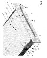
- a pleated filter 1 which consists of a pleated nonwoven and in Area of its long sides 13, 14 in each case a glued or welded Edge 23, 24 has, together with a cover 2, which in this embodiment consists of a polymeric material that is pre-assembled Unit 4.
- the pre-assembled unit 4 is during its intended use Inserted into the filter housing 3 in such a way that the pleated filter 1 is completely enclosed by the filter housing 3 and the Cover 2 touches the filter housing 3 at the end and seals.
- the Pleated filter 1 and the lid 2 touch each other directly in the sealing Area of the upstream last fold 6 of the pleated filter 1 and of the sword 5 of the lid 2. Since the pleated filter is a wearing part acts, which, if necessary, can be replaced separately and easily the pleated filter 1 is detachably connected to the cover 2 in a non-destructive manner.
- the pleated filter 1 is form-fitting connected to the cover, the positive connection by the upstream 8th sword 5 engaging in the last end fold 6 and the locking cams 19, 20 is formed.
- the locking cams 19, 20 hold the pleated filter 1 on the longitudinal rails 15, 16 of the abutment 12 down.
- the sword 5 causes a captive Assignment of the pleated filter 1 on the cover 2 in the longitudinal direction 25 of the Pleated filter 1, while the abutment 12 spatially viewed the pleated filter 1, fixed in the other two directions, based on the lid 2.
- the locking cams 19, 20 To remove the pleated filter 1 from the cover 2, the locking cams 19, 20 the holding clips 17, 18 transversely to the longitudinal direction 25 elastically outwards deformed until it meets the upstream boundaries 21, 22 of the long sides Release 13, 14 of the pleated filter 1. Then the pleated filter 1 past the locking cams 19, 20, starting from that facing away from the cover 2 End to be panned towards the viewer until the Sword 5 and the front last fold 6 of the pleated filter 1 out of engagement get and the pleated filter 1 and the lid 2 thereby non-destructive are detachable from each other.
- the assembly of the pleated filter 1 with the lid 2 to the preassembled unit 4 takes place in such a way that the pleated filter 1 with its last front pleat 6 is threaded under the sword 5 of the cover 2 on the upstream side 8. Meanwhile, the pleated filter 1 and the lid 2 close, depending on their Design, about an angle of 30 to 75 ° with each other. Subsequently the pleated filter 1 continues in the direction of the abutment 12 pivoted until the outflow-side boundaries 26, 27 of the long sides 13, 14 touch the longitudinal rails 15, 16 adjacent.
- the handle 10 is on the side 9 of the cover 2 facing away from the pleated filter 1 arranged, which is an integral and material-integral part of the Cover 2 forms. This handle 10 facilitates the assembly or disassembly of the pre-assembled unit 4 with the filter housing 3.
- FIG. 2 shows a section of the preassembled unit 4 from FIG. 1 in an enlarged view.
- the locking cams 19, 20 each have a run-up slope 28, 29 on the side facing the cover 2, which causes the pleated filter 1 to automatically expand the retaining clips 17, 18 transversely to the longitudinal direction 25 when it is mounted with the cover 2 to the preassembled unit 4 , The assembly of the pleated filter 1 with the cover 2 is thereby considerably simplified.
- the cover 2 is shown as an individual part in a perspective view obliquely from above.
- the two retaining clips 17, 18 are connected on the side facing away from the locking cams 19, 20 by a connecting web 30, which additionally ensures dimensional stability of the retaining clips 17, 18 formed integrally into one another and made of the same material as the cover 2, and thereby ensures sufficient pretension the retaining clips 17, 18 on the long sides 13, 14 of the pleated filter 1.
- the lid 2 is shown obliquely from below.
- the essentially L-shaped sword 5 arranged that on the upstream side 8 of the pleated filter 1 in the last end Fold 6 of the pleated filter 1 engages sealingly.
- the upstream side lays down last edge of the last end fold 6 sealing against the sword 5 and prevents leakage.
- the sword 5 forms a protection against loss and prevents the pleated filter 1 in the longitudinal direction 25 from the Holding clips 17, 18 of the cover 2 slips.
Landscapes
- Chemical & Material Sciences (AREA)
- Chemical Kinetics & Catalysis (AREA)
- Engineering & Computer Science (AREA)
- Mechanical Engineering (AREA)
- Combustion & Propulsion (AREA)
- General Engineering & Computer Science (AREA)
- Filtering Of Dispersed Particles In Gases (AREA)
- Separation By Low-Temperature Treatments (AREA)
- Piezo-Electric Or Mechanical Vibrators, Or Delay Or Filter Circuits (AREA)
- Oscillators With Electromechanical Resonators (AREA)
- Pharmaceuticals Containing Other Organic And Inorganic Compounds (AREA)
- Centrifugal Separators (AREA)
- Separation Using Semi-Permeable Membranes (AREA)
Abstract
Description
Die Erfindung betrifft eine Filteranordnung, umfassend einen Faltenfilter und einen Deckel eines Filtergehäuses.The invention relates to a filter arrangement comprising a pleated filter and a cover of a filter housing.
Eine solche Filteranordnung ist bekannt. Dabei wird der Faltenfilter als Einzelteil
zunächst im Filtergehäuse montiert, wobei die Montageöffnung des Filtergehäuses
anschließend durch den Deckel verschlossen wird. Der Deckel und
der Faltenfilter werden mittels einer separat erzeugten Dichtung gegeneinander
abgedichtet.
Dabei ist allerdings zu beachten, dass die Montage einer solchen Filteranordnung
wenig zufriedenstellend ist. Die räumliche Zuordnung und/oder die
Abdichtung von Faltenfilter und Deckel zueinander ist im Wesentlichen von
den Fähigkeiten und der Zuverlässigkeit des Monteurs abhängig, wobei fehlerhaft
montierte Faltenfilter und/oder Deckel häufig zu unerwünschten Undichtigkeiten
und/oder zu einem Strömungs-Kurzschluss zwischen der An- und
Abströmseite des Faltenfilters führen. Der Montageaufwand am Band und bei
schlechter Zugänglichkeit des Filtergehäuses ist beträchtlich.Such a filter arrangement is known. The pleated filter is first assembled as a single part in the filter housing, the mounting opening of the filter housing then being closed by the cover. The lid and the pleated filter are sealed against each other by means of a separately produced seal.
It should be noted, however, that the assembly of such a filter arrangement is unsatisfactory. The spatial assignment and / or sealing of the pleated filter and cover to one another essentially depends on the skills and reliability of the fitter, with incorrectly installed pleated filters and / or covers often leading to undesired leaks and / or to a flow short circuit between the connection and outflow side of the pleated filter. The assembly work on the belt and if the filter housing is difficult to access is considerable.
Der Erfindung liegt die Aufgabe zugrunde, eine Filteranordnung der eingangs genannten Art derart weiterzuentwickeln, dass diese einen einfachen und teilearmen Aufbau aufweist und daher einfach und kostengünstig herstellbar ist. Außerdem soll die Gefahr von Montagefehlern auf ein Minimum reduziert sein. Bedarfsweise soll der Faltenfilter besonders einfach austauschbar sein.The invention has for its object a filter arrangement of the beginning to develop the type mentioned in such a way that it is simple and low in parts Has structure and is therefore easy and inexpensive to manufacture. In addition, the risk of assembly errors should be reduced to a minimum. If necessary, the pleated filter should be particularly easy to replace.
Diese Aufgabe wird erfindungsgemäß durch die Merkmale von Anspruch 1
gelöst. Auf vorteilhafte Ausgestaltungen nehmen die Unteransprüche Bezug.This object is achieved by the features of
Zur Lösung der Aufgabe ist eine Filteranordnung vorgesehen, umfassend einen Faltenfilter und einen Deckel eines Filtergehäuses, wobei der Faltenfilter und der Deckel eine vormontierbare Einheit bilden und zerstörungsfrei lösbar sowie im Wesentlichen dichtend miteinander verbunden sind. Hierbei ist von Vorteil, dass die Filteranordnung im Wesentlichen nur aus drei Teilen besteht, nämlich dem Faltenfilter, der mit dem Deckel die vormontierbare Einheit bildet und dem Filtergehäuse, in das die vormontierbare Einheit einsetzbar ist. Von hervorzuhebendem Vorteil ist dabei außerdem, dass der Faltenfilter und der Deckel, die die vormontierbare Einheit bilden, sowohl miteinander verbunden als auch gegeneinander abgedichtet sind. Durch die zerstörungsfrei lösbare Verbindung des Faltenfilters am Deckel kann der Faltenfilter bedarfsweise einfach ausgetauscht werden; der Deckel ist nahezu beliebig oft wiederverwendbar. Besonders vorteilhaft, weil einfach, ist die Filteranordnung dann, wenn der Faltenfilter unmittelbar, d.h. unter Vermeidung der Verwendung einer separat hergestellten Dichtung, dichtend mit dem Deckel verbunden ist. Durch die aus nur zwei Teilen bestehende vormontierbare Einheit sind Montagefehler und die Montagedauer deutlich reduziert.To achieve the object, a filter arrangement is provided, comprising a pleated filter and a cover of a filter housing, the pleated filter and the cover form a preassembled unit and can be detached without being destroyed and are essentially sealed together. Here is from Advantage that the filter arrangement essentially consists of only three parts, namely the pleated filter, which forms the preassembled unit with the lid and the filter housing in which the preassembled unit can be inserted. Of Another advantage to be emphasized is that the pleated filter and the Lids, which form the preassembled unit, are both connected to one another are also sealed against each other. Due to the non-destructively detachable Connection of the pleated filter to the lid can be done if necessary can be easily exchanged; the lid can be reused almost any number of times. The filter arrangement is particularly advantageous because it is simple, if the pleated filter immediately, i.e. avoiding the use of a separately manufactured seal, sealingly connected to the lid. By the preassembled unit consisting of only two parts are assembly errors and significantly reduced the assembly time.
Der Faltenfilter und der Deckel können kraft- und/oder formschlüssig miteinander
verbunden sein. Eine kraftschlüssige Verbindung von Faltenfilter und
Deckel kann beispielsweise dadurch erzielt werden, dass der Faltenfilter ausschließlich
reibschlüssig in einer Führungsschiene des Deckels angeordnet ist.
Zusätzlich oder alternativ kann der Faltenfilter formschlüssig mit dem Deckel
verbunden sein. Dazu kann es vorgesehen sein, dass der Deckel und/oder der
Faltenfilter beispielsweise einen Vorsprung aufweisen, der in eine Hinterschneidung
des Faltenfilters und/oder des Deckels eingreift.
Im Hinblick auf den, bezogen auf den Deckel, vergleichsweise empfindlichen
Faltenfilter, der aus einem Vliesstoff bestehen kann, wird einer hauptsächlich
formschlüssigen Verbindung von Faltenfilter und Deckel im Rahmen der vorliegenden
Erfindung der Vorzug gegeben. Die mechanischen Belastungen auf
den Faltenfilter während der Montage sind dadurch weitesgehend reduziert.The pleated filter and the cover can be connected to one another in a non-positive and / or positive manner. A non-positive connection between the pleated filter and the cover can be achieved, for example, in that the pleated filter is arranged exclusively in a frictional manner in a guide rail of the cover. Additionally or alternatively, the pleated filter can be positively connected to the cover. For this purpose, it can be provided that the cover and / or the pleated filter have, for example, a projection which engages in an undercut of the pleated filter and / or the cover.
With regard to the comparatively sensitive pleated filter, which can be made of a nonwoven fabric, a mainly positive connection between pleated filter and cover is preferred within the scope of the present invention. The mechanical loads on the pleated filter during assembly are largely reduced.
Der Deckel kann aus einem polymeren Werkstoff bestehen. Gelangt die Filteranordnung beispielsweise in Kraftfahrzeugen als Fahrzeuginnenraum-Filter zur Anwendung, ist von Vorteil, dass der Deckel trotz Beaufschlagung mit Feuchtigkeit rostfrei ist. Außerdem ist der Deckel aus polymerem Werkstoff im Vergleich zu Deckeln aus einem metallischen Werkstoff leichter, was in Verbindung mit anderen Leichtbauteilen ein geringes Gesamtgewicht des Fahrzeugs begünstigt. Das Recycling von polymeren Werkstoffen ist außerdem mit einem geringen Energieeinsatz möglich.The lid can be made of a polymeric material. Get the Filter arrangement, for example in motor vehicles as a vehicle interior filter to use, it is advantageous that the lid despite being loaded with Moisture is rustproof. In addition, the lid is made of polymer material in the Compared to lids made of a metallic material lighter, which in connection a low overall weight of the vehicle with other lightweight components favored. The recycling of polymeric materials is also involved low energy consumption possible.
Der Deckel kann ein Schwert aufweisen, das in der dem Deckel zugewandten, letzten Falte der Stirnseite des Faltenfilters im Wesentlichen dichtend angeordnet ist. Das Schwert des Deckels hat zwei Funktionen. Zum einen bewirkt das Schwert durch seine formschlüssige Anordnung in der Falte des Faltenfilters eine verliersichere Zuordnung der Bestandteile der vormontierbaren Einheit. Der Faltenfilter ist in seiner Längsrichtung am Deckel fixiert. Außerdem bildet das Schwert neben der zuvor beschriebenen Verliersicherung die Dichtung zwischen Deckel und Filter. Während der bestimmungsgemäßen Verwendung der Filteranordnung berührt das Schwert den Faltenfilter im Wesentlichen dichtend, so dass es einer separat erzeugten, beispielsweise aus Schaumstoff bestehenden Dichtung nicht bedarf. Eine kostengünstige Herstellung und einfache Montage der Filteranordnung ist dadurch begünstigt.The lid can have a sword, which in the last fold of the end face of the pleated filter arranged essentially sealing is. The sword of the lid has two functions. For one, it causes the sword thanks to its form-fitting arrangement in the fold of the pleated filter a captive assignment of the components of the preassembled unit. The pleated filter is fixed to the cover in its longitudinal direction. Moreover the sword forms the seal in addition to the previously described captive device between cover and filter. During the intended use In the filter arrangement, the sword essentially touches the pleated filter sealing, so that it is a separately produced one, for example made of foam existing seal does not need. An inexpensive manufacture and simple Assembly of the filter arrangement is favored.
Das Schwert kann auf der Anströmseite des Faltenfilters in der letzten stirnseitigen Falte angeordnet sein. Das Schwert bildet dadurch ein Widerlager zu einem weiteren Widerlager, das auf der Abströmseite des Faltenfilters angeordnet ist.The sword can be found on the upstream side of the pleated filter in the last front Fold be arranged. The sword forms an abutment another abutment, which is arranged on the downstream side of the pleated filter is.
Der Deckel und das Schwert können einstückig und materialeinheitlich ausgebildet sein. Auch durch eine derartige Ausgestaltung wird die Lösung der eingangs gestellten Aufgabe begünstigt, da die gesamte Filteranordnung einen einfachen, teilearmen Aufbau aufweist, dadurch kostengünstig herstellbar ist und Montagefehler durch den teilearmen Aufbau weitgehend ausgeschlossen sind. Außerdem gelangen nur wenige unterschiedliche Materialien zur Anwendung, so dass die Filteranordnung einfach recycelbar ist.The lid and the sword can be made in one piece and of the same material his. With such a configuration, the solution of the beginning task favored, since the entire filter assembly one has a simple, parts-poor structure, which is inexpensive to manufacture and assembly errors largely excluded due to the low-part construction are. In addition, only a few different materials are used, so that the filter arrangement is easily recyclable.
Das Schwert kann im Wesentlichen L-förmig ausgebildet sein. Das Einfädeln der dem Deckel zugewandten, letzten Falte der Stirnseite des Faltenfilters in das Schwert ist dadurch besonders einfach möglich.The sword can be essentially L-shaped. Threading the last fold of the pleated filter facing the cover in this makes the sword particularly easy.
Der Deckel kann auf der dem Faltenfilter zugewandten Seite einen Griff zur Montage oder Demontage der vormontierbaren Einheit aufweisen, wobei der Deckel und der Griff bevorzugt ebenfalls einstückig und materialeinheitlich ausgebildet sind. Das Handling der vormontierbaren Einheit ist durch den Griff verbessert. Es ist nicht erforderlich, die vormontierbare Einheit während ihrer Montage mit dem Filtergehäuse am Faltenfilter zu berühren. Eine Beschädigung des Faltenfilters und daraus resultierende, montagebedingte Funktionsbeeinträchtigungen sind weitgehend ausgeschlossen.The lid can have a handle on the side facing the pleated filter Have assembly or disassembly of the preassembled unit, the The lid and the handle are preferably also in one piece and of the same material are trained. The handling of the pre-assembled unit is by the handle improved. It is not necessary to use the pre-assembled unit during its Touch the assembly with the filter housing on the pleated filter. Damage of the pleated filter and the resulting functional impairments due to assembly are largely excluded.
Der Deckel kann auf der dem Faltenfilter zugewandten Seite ein Widerlager zur Lagerung des Faltenfilters am Deckel aufweisen. Wie bereits zuvor bei der einstückigen und materialeinheitlichen Ausgestaltung des Schwerts mit dem Deckel und/oder des Griffs mit dem Deckel ausgeführt, ist auch hier der einfache und kostengünstige Aufbau, die einfache Montage durch die Vermeidung vieler, separat zu erzeugender Bauteile und die gute Recyclingfähigkeit von hervorzuhebendem Vorteil.The cover can have an abutment on the side facing the pleated filter for storing the pleated filter on the cover. As before with the one-piece and material-uniform design of the sword with the Cover and / or the handle with the lid is also the simple one and inexpensive construction, the easy assembly by avoiding many components to be produced separately and the good recyclability of advantage to be emphasized.
Das Widerlager kann durch zwei die Längsseiten des Faltenfilters abströmseitig zumindest teilweise untergreifende Längsschienen gebildet sein. Dadurch, dass beide Längsseiten des Faltenfilters abströmseitig von den Längsschienen untergriffen sind, ergibt sich eine exakte Zuordnung der Lage des Faltenfilters bezogen auf den Deckel. Die Verwendung nur einer Längsschiene würde demgegenüber eine verkantete Zuordnung des Faltenfilters zum Deckel und dadurch möglicherweise Funktionsbeeinträchtigungen begünstigen. Speziell im Hinblick auf die Abdichtung des Faltenfilters durch das Schwert ist eine exakte Zuordnung des Faltenfilters zum Deckel besonders zweckmäßig.The abutment can have two sides of the long side of the pleated filter on the downstream side be formed at least partially under longitudinal rails. The fact that both long sides of the pleated filter on the downstream side of the Longitudinal rails are gripped, there is an exact assignment of the position of the pleated filter related to the lid. The use of only one longitudinal rail in contrast, a tilted assignment of the pleated filter to Cover and thereby possibly impair functionality. Especially with regard to the sealing of the pleated filter by the Sword is an exact assignment of the pleated filter to the lid in particular appropriate.
Das Widerlager kann durch zwei die Längsseiten des Faltenfilters zumindest teilweise U-förmig umgreifende Halteklammern gebildet sein. Die Längsschienen können einen Bestandteil der Halteklammern bilden. Die exakte Positionierung des Faltenfilters bezogen auf den Deckel ist durch eine derartige Ausgestaltung weiter verbessert, wobei die Möglichkeit besteht, die Halteklammern auf der dem Faltenfilter zugewandten Seite mit jeweils einer Oberflächenprofilierung zu versehen, die die Längsseiten des Faltenfilters anliegend berühren und dadurch zusätzlich zu der formschlüssigen Verbindung durch das Schwert, das in die letzte Falte der Stirnseite des Faltenfilters eingreift, eine kraftschlüssige Verbindung bewirken. Durch die Halteklammern wird die anströmseitige und abströmseitige Begrenzung zumindest eines Teils der Längsseiten des Faltenfilters überdeckt.The abutment can at least by two the long sides of the pleated filter partially formed U-shaped retaining clips. The longitudinal rails can form part of the retaining clips. The exact one Positioning of the pleated filter in relation to the cover is done by such Design further improved, with the possibility of the retaining clips on the side facing the pleated filter, each with a surface profile to be provided, which the adjacent sides of the pleated filter touch and in addition to the positive connection by the sword that engages in the last fold of the face of the pleated filter, effect a positive connection. Through the retaining clips the upstream and downstream limits of at least part of the Long sides of the pleated filter covered.
Das Widerlager kann auf zumindest einer Längsseite des Faltenfilters zumindest einen elastisch nachgiebigen Rastnocken aufweisen, der die anströmseitige Begrenzung der entsprechenden Längsseite zumindest teilweise überdeckt. Bevorzugt ist jedoch jede Längsseite des Faltenfilters anströmseitig von jeweils zumindest einem elastisch nachgiebigen Rastnocken zumindest teilweise überdeckt. Im Hinblick auf ein einfaches Handling ist von Vorteil, dass der Faltenfilter mittels der Rastnocken in das Widerlager einschnappbar ist. Die Montage des Faltenfilters mit dem Deckel erfolgt bevorzugt derart, dass der Faltenfilter mit seiner letzten anströmseitigen Falte unter das Schwert des Deckels eingefädelt und anschließend in Richtung des Widerlagers geschwenkt wird, so lange, bis die abströmseitige Längsseite des Faltenfilters auf dem Widerlager aufliegt. Wenn die Längsseiten des Faltenfilters das Widerlager anliegend berühren, rasten die zunächst elastisch aufgeweiteten Rastnocken über der anströmseitigen Begrenzung der Längsseite des Faltenfilters widerhakenförmig ein und erzeugen dadurch eine unverlierbare Verbindung des Faltenfilters am Deckel, wobei beide Teile die vormontierbare Einheit bilden. Zur Trennung des Faltenfilters vom Deckel werden die Rastnocken solange elastisch entgegen ihrer Einrast-Richtung verformt, bis sie die anströmseitige Begrenzung des Faltenfilters freigeben und dieser, entgegen der Montagerichtung solange geschwenkt wird, bis die letzte anströmseitige Falte unter dem Schwert hervorgezogen und der Faltenfilter dadurch vom Deckel zerstörungsfrei getrennt werden kann. The abutment can at least on at least one long side of the pleated filter have an elastically resilient locking cam, which the upstream Limitation of the corresponding long side at least partially covered. However, each long side of the pleated filter is preferably upstream of at least partially each at least one elastically resilient locking cam covered. In terms of easy handling, it is advantageous that the pleated filter can be snapped into the abutment by means of the locking cams. The pleated filter is preferably mounted with the cover in such a way that the Pleated filter with its last upstream pleat under the sword of the Cover threaded and then towards the abutment is pivoted until the long side of the pleated filter on the downstream side rests on the abutment. If the long sides of the pleated filter If the abutment touches the abutment, the elastically widened ones snap into place Snap cams over the upstream boundary of the long side of the pleated filter barb-shaped and thereby create a captive connection of the pleated filter on the cover, with both parts being the preassembled unit form. The locking cams are used to separate the pleated filter from the cover as long as it is elastically deformed against its snap-in direction until it Release the upstream limitation of the pleated filter and counter it the assembly direction is pivoted until the last upstream side Pull out the fold under the sword and the pleated filter thereby from Lid can be separated non-destructively.
Ein Ausführungsbeispiel der erfindungsgemäßen Filteranordnung ist in den Figuren 1 bis 4 gezeigt und wird nachfolgend näher beschrieben.An embodiment of the filter arrangement according to the invention is in the Figures 1 to 4 shown and will be described in more detail below.
Die Figuren 1 bis 4 zeigen jeweils in schematischer Darstellung:
- Fig. 1
- ein Ausführungsbeispiel der erfindungsgemäßen Filteranordnung, wobei die vormontierbare Einheit teilweise in ein Filtergehäuse eingeschoben ist,
- Fig. 2
- einen vergrößerten Ausschnitt der vormontierbaren Einheit aus Fig. 1,
- Fig. 3
- den Deckel als Einzelteil in perspektivischer Darstellung von schräg oben,
- Fig. 4
- den Deckel aus Fig. 3 in einer perspektivischen Ansicht von schräg unten.
- Fig. 1
- An embodiment of the filter arrangement according to the invention, wherein the preassembled unit is partially inserted into a filter housing,
- Fig. 2
- 2 shows an enlarged section of the preassembled unit from FIG. 1,
- Fig. 3
- the lid as an individual part in a perspective view obliquely from above,
- Fig. 4
- 3 in a perspective view obliquely from below.
In Fig. 1 ist ein Ausführungsbeispiel der erfindungsgemäßen Filteranordnung
gezeigt. Ein Faltenfilter 1, der aus einem plissierten Vliesstoff besteht und im
Bereich seiner Längsseiten 13, 14 jeweils eine aufgeleimte oder aufgeschweißte
Kante 23, 24 aufweist, bildet zusammen mit einem Deckel 2, der in
diesem Ausführungsbeispiel aus einem polymeren Werkstoff besteht, die vormontierbare
Einheit 4. Die vormontierte Einheit 4 ist während ihrer bestimmungsgemäßen
Verwendung derart in das Filtergehäuse 3 eingeschoben,
dass der Faltenfilter 1 vollständig vom Filtergehäuse 3 umschlossen ist und der
Deckel 2 das Filtergehäuse 3 stirnseitig anliegend und dichtend berührt. Der
Faltenfilter 1 und der Deckel 2 berühren einander unmittelbar dichtend im
Bereich der anströmseitig letzten stirnseitigen Falte 6 des Faltenfilters 1 und
des Schwerts 5 des Deckels 2. Da es sich bei dem Faltenfilter um ein Verschleißteil
handelt, das bedarfsweise separat und einfach auswechselbar sein
soll, ist der Faltenfilter 1 zerstörungsfrei lösbar mit dem Deckel 2 verbunden.1 shows an embodiment of the filter arrangement according to the invention
shown. A
In dem hier gezeigten Ausführungsbeispiel ist der Faltenfilter 1 formschlüssig
mit dem Deckel verbunden, wobei der Formschluss durch das anströmseitig 8
in die letzte stirnseitige Falte 6 eingreifende Schwert 5 und die Rastnocken 19,
20 gebildet ist. Die Rastnocken 19, 20 halten den Faltenfilter 1 auf den Längsschienen
15, 16 des Widerlagers 12 nieder. Das Schwert 5 bewirkt eine unverlierbare
Zuordnung des Faltenfilters 1 am Deckel 2 in Längsrichtung 25 des
Faltenfilters 1, während das Widerlager 12 den Faltenfilter 1, räumlich gesehen,
in den beiden anderen Richtungen, bezogen auf den Deckel 2 fixiert.In the exemplary embodiment shown here, the
Zur Demontage des Faltenfilters 1 vom Deckel 2 werden die Rastnocken 19, 20
der Halteklammern 17, 18 quer zur Längsrichtung 25 elastisch nach außen
verformt, solange, bis sie die anströmseitigen Begrenzungen 21, 22 der Längsseiten
13, 14 des Faltenfilters 1 freigeben. Anschließend kann der Faltenfilter 1
an den Rastnocken 19, 20 vorbei, beginnend von dem dem Deckel 2 abgewandten
Ende in Richtung des Betrachters geschwenkt werden, bis das
Schwert 5 und die stirnseitig letzte Falte 6 des Faltenfilters 1 außer Eingriff
gelangen und der Faltenfilter 1 sowie der Deckel 2 dadurch zerstörungsfrei
voneinander lösbar sind.To remove the
Die Montage des Faltenfilters 1 mit dem Deckel 2 zur vormontierbaren Einheit
4 erfolgt derart, dass der Faltenfilter 1 mit seiner letzten stirnseitigen Falte 6
auf der Anströmseite 8 unter das Schwert 5 des Deckels 2 eingefädelt wird.
Währenddessen schließen der Faltenfilter 1 und der Deckel 2, je nach deren
Ausgestaltung, etwa einen Winkel von 30 bis 75° miteinander ein. Anschließend
wird der Faltenfilter 1 solange in Richtung des Widerlagers 12
geschwenkt, bis die abströmseitigen Begrenzungen 26, 27 der Längsseiten 13,
14 die Längsschienen 15, 16 anliegend berühren. Sobald die abströmseitigen
Begrenzungen 26, 27 der Längsseiten 13, 14 die Längsschienen 15, 16 berühren,
schnappen die Rastnocken 19, 20, die einen Bestandteil der als Widerlager
12 ausgebildeten Halteklammern 17, 18 bilden, über den anströmseitigen
Begrenzungen 21, 22 der Längsseiten 13, 14 ein. Die vormontierbare Einheit 4
ist nun fertiggestellt, um im Filtergehäuse 3 montiert zu werden.The assembly of the
Auf der dem Faltenfilter 1 abgewandten Seite 9 des Deckels 2 ist der Griff 10
angeordnet, der einen einstückigen und materialeinheitlichen Bestandteil des
Deckels 2 bildet. Dieser Griff 10 erleichtert die Montage oder Demontage der
vormontierbaren Einheit 4 mit dem Filtergehäuse 3.The
In Figur 2 ist ein Ausschnitt aus der vormontierten Einheit 4 aus Fig. 1 in vergrößerter
Darstellung gezeigt. Die Rastnocken 19, 20 haben auf der dem
Deckel 2 zugewandten Seite jeweils eine Auflaufschräge 28, 29, die bewirkt,
dass der Faltenfilter 1 bei seiner Montage mit dem Deckel 2 zur vormontierten
Einheit 4 die Halteklammern 17, 18 selbsttätig quer zur Längsrichtung 25 elastisch
aufweitet. Die Montage des Faltenfilters 1 mit dem Deckel 2 ist dadurch
wesentlich vereinfacht.
In Fig. 3 ist der Deckel 2 als Einzelteil in einer perspektivischen Darstellung
von schräg oben gezeigt. Die beiden Halteklammern 17, 18 sind auf der den
Rastnocken 19, 20 abgewandten Seite durch einen Verbindungssteg 30 verbunden,
der zusätzlich für eine Formbeständigkeit der einstückig ineinander
übergehend und materialeinheitlich mit dem Deckel 2 ausgebildeten Halteklammern
17, 18 sorgt, und dadurch für eine ausreichende Vorspannung der
Halteklammern 17, 18 an den Längsseiten 13, 14 des Faltenfilters 1.FIG. 2 shows a section of the preassembled unit 4 from FIG. 1 in an enlarged view. The locking
In Fig. 3, the
In Fig. 4 ist der Deckel 2 von schräg unten gezeigt. Auf der dem Griff 10 abgewandten
Seite des Deckels 2 ist das im Wesentlichen L-förmige Schwert 5
angeordnet, das auf der Anströmseite 8 des Faltenfilters 1 in die letzte stirnseitige
Falte 6 des Faltenfilters 1 dichtend eingreift. Während der bestimmungsgemäßen
Verwendung der Filteranordnung legt sich die anströmseitige
letzte Kante der letzten stirnseitigen Falte 6 dichtend an das Schwert 5 an und
verhindert dadurch eine Leckage. Außerdem bildet das Schwert 5 eine Verliersicherung
und verhindert, dass der Faltenfilter 1 in Längsrichtung 25 aus den
Halteklammern 17, 18 des Deckels 2 rutscht. In Fig. 4, the
- 11
- Faltenfilterpleated filter
- 22
- Deckelcover
- 33
- Filtergehäusefilter housing
- 44
- Vormontierbare Einheit, bestehend aus 1 und 2Pre-assembled unit consisting of 1 and 2
- 55
- Schwertsword
- 66
- Letzte Falte (anströmseitig)Last fold (upstream)
- 77
- Stirnseite von 1Front of 1
- 88th
- Anströmseite von 1Upstream side of 1
- 99
- Seite des Griffs an 2Side of the handle on 2
- 1010
- GriffHandle
- 1111
- Seite des Faltenfilters an 2Side of the pleated filter on 2
- 1212
- Widerlagerabutment
- 1313
- Längsseite von 1, linksLong side of 1, left
- 1414
- Längsseite von 1, rechtsLong side of 1, right
- 1515
- Längsschiene, linksLongitudinal rail, left
- 1616
- Längsschiene, rechtsLongitudinal rail, right
- 1717
- Halteklammer, linksRetaining clip, left
- 1818
- Halteklammer, rechtsHolding bracket, right
- 1919
- Rastnocken, linksLatch cams, left
- 2020
- Rastnocken, rechtsLatch cams, right
- 2121
- Anströmsseitige Begrenzung von 13Inlet limit of 13
- 2222
- Anströmsseitige Begrenzung von 14 Inlet limit of 14
- 2323
- Kante an 1, linksEdge at 1, left
- 2424
- Kante an 1, rechtsEdge at 1, right
- 2525
- Längsrichtung von 1Longitudinal direction of 1
- 2626
- Abströmseitige Begrenzung von 13Downflow limitation of 13
- 2727
- Abströmseitige Begrenzung von 14Outflow limitation of 14
- 2828
- Auflaufschräge von 19Run-up slope from 19
- 2929
- Auflaufschräge von 20Run-up slope of 20
- 3030
- Verbindungsstegconnecting web
- 3131
- Abströmseite von 1Outflow side of 1
Claims (17)
Applications Claiming Priority (2)
| Application Number | Priority Date | Filing Date | Title |
|---|---|---|---|
| DE10123969 | 2001-05-17 | ||
| DE10123969A DE10123969C1 (en) | 2001-05-17 | 2001-05-17 | Filter device, for vehicle air conditioning system, has replaceable filter element provided by folded filter snap-fitted to filter housing cover for providing pre-assembled unit |
Publications (2)
| Publication Number | Publication Date |
|---|---|
| EP1260263A1 true EP1260263A1 (en) | 2002-11-27 |
| EP1260263B1 EP1260263B1 (en) | 2004-10-06 |
Family
ID=7685095
Family Applications (1)
| Application Number | Title | Priority Date | Filing Date |
|---|---|---|---|
| EP02004588A Expired - Lifetime EP1260263B1 (en) | 2001-05-17 | 2002-02-28 | Filter assembly |
Country Status (11)
| Country | Link |
|---|---|
| US (1) | US6749657B2 (en) |
| EP (1) | EP1260263B1 (en) |
| JP (1) | JP3766812B2 (en) |
| KR (1) | KR100485009B1 (en) |
| AT (1) | ATE278451T1 (en) |
| BR (1) | BR0201856B1 (en) |
| CZ (1) | CZ299328B6 (en) |
| DE (2) | DE10123969C1 (en) |
| ES (1) | ES2228996T3 (en) |
| PL (1) | PL200144B1 (en) |
| ZA (1) | ZA200203923B (en) |
Cited By (3)
| Publication number | Priority date | Publication date | Assignee | Title |
|---|---|---|---|---|
| FR2865159A1 (en) * | 2004-01-21 | 2005-07-22 | Valeo Climatisation | Opening sealing device for ventilation, heating and/or air conditioning installation of motor vehicle, has part with guiding pin, and another part with guiding units and tongue exerting force on filtration unit having large surface |
| EP2397210A1 (en) * | 2010-06-17 | 2011-12-21 | Carl Freudenberg KG | Assembly with a cover and a self-supporting filter element |
| FR3022470A1 (en) * | 2014-06-18 | 2015-12-25 | Sandra Celine Severine Lefrancois | FILTER CARTRIDGE HOLDER AGAINST EXTERIOR POLLUTION, DISPOSABLE ON WALL-MOUNTED ENTRANCES, DOORS, WINDOWS, SHUTTER BOXES COUPLED TO MECHANICAL VENTILATION. |
Families Citing this family (14)
| Publication number | Priority date | Publication date | Assignee | Title |
|---|---|---|---|---|
| DE10317493B4 (en) * | 2003-01-24 | 2007-06-14 | Helsa-Automotive Gmbh & Co. Kg | Filter element for a filter holder |
| TWI354011B (en) * | 2003-05-16 | 2011-12-11 | Semiconductor Energy Lab | Carbazole derivative, organic semiconductor elemen |
| DE10334567A1 (en) * | 2003-07-28 | 2005-02-24 | Behr Gmbh & Co. Kg | A filter assembly |
| DE10356311A1 (en) * | 2003-11-28 | 2005-06-23 | Behr Gmbh & Co. Kg | A filter assembly |
| DE102005019675A1 (en) * | 2005-04-26 | 2006-11-02 | Behr Gmbh & Co. Kg | One-part, especially injection molded, filter unit for vehicle internal ventilation system has predetermined breaking point between filter and cover to allow exchange of part |
| US7597735B2 (en) * | 2006-12-21 | 2009-10-06 | Cummins Filtration Ip Inc. | Apparatus and system for uniform sealing force in an air filter assembly |
| DE202008010474U1 (en) | 2008-08-06 | 2009-12-17 | Mann+Hummel Gmbh | filter system |
| KR101016549B1 (en) * | 2010-08-12 | 2011-02-24 | 비에이치아이 주식회사 | Strainer wall structure including curved sections and manufacturing method for the strainer wall structure and filtering method using the strainer wall structure |
| JP6262513B2 (en) * | 2013-12-12 | 2018-01-17 | 株式会社日本クライメイトシステムズ | Air conditioner for vehicles |
| DE102015203138A1 (en) | 2015-02-20 | 2016-08-25 | Mahle International Gmbh | Air filter element and air filter |
| IT201800009906A1 (en) * | 2018-10-30 | 2020-04-30 | Denso Thermal Systems Spa | Cover for filter element. |
| CN212700928U (en) * | 2020-04-29 | 2021-03-16 | 赛格威科技有限公司 | Filtering device and all-terrain vehicle |
| WO2021260811A1 (en) * | 2020-06-23 | 2021-12-30 | 三菱電機株式会社 | Filter frame and ventilation device |
| CN112304341A (en) * | 2020-10-22 | 2021-02-02 | 上海工程技术大学 | Strong electromagnetic field interference resistant detection equipment |
Citations (9)
| Publication number | Priority date | Publication date | Assignee | Title |
|---|---|---|---|---|
| US2655091A (en) * | 1950-08-07 | 1953-10-13 | Rex W Geiger | Filter |
| US4925468A (en) * | 1987-10-14 | 1990-05-15 | Nippondenso Co., Ltd. | Filter device provided in an air conditioning device |
| US5030264A (en) * | 1989-04-06 | 1991-07-09 | Filterwerk Mann & Hummel Gmbh | Air intake filter for an internal combustion engine |
| US5435837A (en) * | 1993-12-06 | 1995-07-25 | Lewis; Keith B. | Ion generation structure in environmental systems |
| EP0684152A1 (en) * | 1994-05-25 | 1995-11-29 | Honda Giken Kogyo Kabushiki Kaisha | Air filter mounting structure in air conditioning device |
| US5494497A (en) * | 1992-12-30 | 1996-02-27 | Hyundai Motor Company | Air cleaner assembly for vehicle |
| EP0744309A1 (en) * | 1995-05-26 | 1996-11-27 | FIAT AUTO S.p.A. | An air filtration device for an air-conditioning system, in particular for a vehicle |
| US6089202A (en) * | 1997-08-21 | 2000-07-18 | Denso Corporation | Air-supply module for internal combustion engine |
| GB2348153A (en) * | 1999-03-25 | 2000-09-27 | Draftex Ind Ltd | Easily removable air filter for internal combustion engine air intake. |
Family Cites Families (15)
| Publication number | Priority date | Publication date | Assignee | Title |
|---|---|---|---|---|
| US4773922A (en) * | 1987-07-22 | 1988-09-27 | The United States Of America As Represented By The United States Department Of Energy | Remotely serviced filter and housing |
| US4900344A (en) * | 1987-11-10 | 1990-02-13 | Jvj Enterprises, Inc. | Portable room air filter |
| DE4329367C1 (en) * | 1993-09-01 | 1995-04-27 | Juergen Junker | Filter insert |
| US5639287A (en) * | 1994-05-16 | 1997-06-17 | Minnesota Mining And Manufacturing Company | Filter system for filtering fluids |
| DE4443676C2 (en) * | 1994-12-08 | 1998-08-13 | Hengst Walter Gmbh & Co Kg | Filters with a filter housing and a replaceable filter element arranged therein |
| JP3379275B2 (en) * | 1995-04-21 | 2003-02-24 | 日産自動車株式会社 | Vehicle air conditioner and filter mounting structure |
| JPH09290630A (en) * | 1996-04-30 | 1997-11-11 | Nissan Motor Co Ltd | Air-conditioning filter for vehicle |
| WO1998017368A1 (en) * | 1996-10-18 | 1998-04-30 | Chapman Rick L | High efficiency permanent air filter |
| US5740774A (en) * | 1996-12-18 | 1998-04-21 | Siemens Electric Limited | Engine induction air system having improved air filter accessibility |
| KR19980046748U (en) * | 1996-12-28 | 1998-09-25 | 박병재 | Car blower filter |
| US6033453A (en) * | 1997-01-30 | 2000-03-07 | Weddell, Iii; Robert W. | Re-usable frame support rack for replaceable pleated-media filter core |
| US5865863A (en) * | 1997-05-08 | 1999-02-02 | Siemens Electric Limited | Combined air cleaner-resonator |
| DE19850576C2 (en) * | 1998-11-03 | 2002-06-27 | Freudenberg Carl Kg | Filter cartridge assembly |
| FR2806318B1 (en) * | 2000-03-15 | 2002-10-25 | Valeo | FILTRATION DEVICE FOR FITTING A VENTILATION AND / OR HEATING AND / OR AIR CONDITIONING APPARATUS, IN PARTICULAR FOR A MOTOR VEHICLE |
| US6419718B1 (en) * | 2000-10-13 | 2002-07-16 | Donaldson Company, Inc. | Cover member and air cleaner construction; use; and, method of assembly |
-
2001
- 2001-05-17 DE DE10123969A patent/DE10123969C1/en not_active Expired - Fee Related
-
2002
- 2002-02-28 EP EP02004588A patent/EP1260263B1/en not_active Expired - Lifetime
- 2002-02-28 ES ES02004588T patent/ES2228996T3/en not_active Expired - Lifetime
- 2002-02-28 DE DE50201191T patent/DE50201191D1/en not_active Expired - Lifetime
- 2002-02-28 AT AT02004588T patent/ATE278451T1/en not_active IP Right Cessation
- 2002-03-13 CZ CZ20020902A patent/CZ299328B6/en not_active IP Right Cessation
- 2002-04-25 PL PL353632A patent/PL200144B1/en not_active IP Right Cessation
- 2002-05-15 KR KR10-2002-0026769A patent/KR100485009B1/en not_active IP Right Cessation
- 2002-05-16 US US10/150,246 patent/US6749657B2/en not_active Expired - Fee Related
- 2002-05-16 ZA ZA200203923A patent/ZA200203923B/en unknown
- 2002-05-17 BR BRPI0201856-0A patent/BR0201856B1/en not_active IP Right Cessation
- 2002-05-17 JP JP2002143519A patent/JP3766812B2/en not_active Expired - Fee Related
Patent Citations (9)
| Publication number | Priority date | Publication date | Assignee | Title |
|---|---|---|---|---|
| US2655091A (en) * | 1950-08-07 | 1953-10-13 | Rex W Geiger | Filter |
| US4925468A (en) * | 1987-10-14 | 1990-05-15 | Nippondenso Co., Ltd. | Filter device provided in an air conditioning device |
| US5030264A (en) * | 1989-04-06 | 1991-07-09 | Filterwerk Mann & Hummel Gmbh | Air intake filter for an internal combustion engine |
| US5494497A (en) * | 1992-12-30 | 1996-02-27 | Hyundai Motor Company | Air cleaner assembly for vehicle |
| US5435837A (en) * | 1993-12-06 | 1995-07-25 | Lewis; Keith B. | Ion generation structure in environmental systems |
| EP0684152A1 (en) * | 1994-05-25 | 1995-11-29 | Honda Giken Kogyo Kabushiki Kaisha | Air filter mounting structure in air conditioning device |
| EP0744309A1 (en) * | 1995-05-26 | 1996-11-27 | FIAT AUTO S.p.A. | An air filtration device for an air-conditioning system, in particular for a vehicle |
| US6089202A (en) * | 1997-08-21 | 2000-07-18 | Denso Corporation | Air-supply module for internal combustion engine |
| GB2348153A (en) * | 1999-03-25 | 2000-09-27 | Draftex Ind Ltd | Easily removable air filter for internal combustion engine air intake. |
Cited By (3)
| Publication number | Priority date | Publication date | Assignee | Title |
|---|---|---|---|---|
| FR2865159A1 (en) * | 2004-01-21 | 2005-07-22 | Valeo Climatisation | Opening sealing device for ventilation, heating and/or air conditioning installation of motor vehicle, has part with guiding pin, and another part with guiding units and tongue exerting force on filtration unit having large surface |
| EP2397210A1 (en) * | 2010-06-17 | 2011-12-21 | Carl Freudenberg KG | Assembly with a cover and a self-supporting filter element |
| FR3022470A1 (en) * | 2014-06-18 | 2015-12-25 | Sandra Celine Severine Lefrancois | FILTER CARTRIDGE HOLDER AGAINST EXTERIOR POLLUTION, DISPOSABLE ON WALL-MOUNTED ENTRANCES, DOORS, WINDOWS, SHUTTER BOXES COUPLED TO MECHANICAL VENTILATION. |
Also Published As
| Publication number | Publication date |
|---|---|
| JP2003053122A (en) | 2003-02-25 |
| US20030005671A1 (en) | 2003-01-09 |
| KR100485009B1 (en) | 2005-04-25 |
| ZA200203923B (en) | 2004-05-17 |
| PL200144B1 (en) | 2008-12-31 |
| DE50201191D1 (en) | 2004-11-11 |
| CZ2002902A3 (en) | 2003-01-15 |
| DE10123969C1 (en) | 2002-11-07 |
| CZ299328B6 (en) | 2008-06-18 |
| JP3766812B2 (en) | 2006-04-19 |
| BR0201856B1 (en) | 2010-11-16 |
| BR0201856A (en) | 2004-04-13 |
| ES2228996T3 (en) | 2005-04-16 |
| US6749657B2 (en) | 2004-06-15 |
| KR20020088369A (en) | 2002-11-27 |
| EP1260263B1 (en) | 2004-10-06 |
| ATE278451T1 (en) | 2004-10-15 |
| PL353632A1 (en) | 2002-11-18 |
Similar Documents
| Publication | Publication Date | Title |
|---|---|---|
| EP3079794B1 (en) | Cabin air filter and filter assembly | |
| EP1260263A1 (en) | Filter assembly | |
| EP3157653A2 (en) | Filter and filter cartridge | |
| EP1005893B1 (en) | Filter element | |
| DE102011015062B4 (en) | Filter housing of an air filter and closure element of a filter housing | |
| DE4443144C1 (en) | Dust filter bag frame incorporates U-shaped outer frame with locking rims | |
| DE102009037999B4 (en) | Filter device, in particular air filter | |
| EP1616736A1 (en) | Folded Filter | |
| DE20122455U1 (en) | Flexible filter | |
| DE102015011339A1 (en) | Filter element with a circumferential seal | |
| EP3446768B1 (en) | Internal air filter and filter assembly | |
| DE102020110996A1 (en) | Filter element for an air filter device of a motor vehicle and air filter device | |
| DE102012012669A1 (en) | Air filter of aerator for filtering air of air conditioning apparatus mounted in motor car, has open recess that is provided for fixing filter frame in receiving area to introduce sides of aerator intended projection portion | |
| DE3524278A1 (en) | Line bushing for lines which are to be passed through a housing wall, especially hose lines and/or pipelines | |
| DE202005011078U1 (en) | Filter element has mounting with slot, into which filter fits and which is closed by plate with hooks which fit around notches in slot, rectangular sealing plate being mounted on end of filter which has slots, through which hooks fit | |
| EP2692559B1 (en) | Air filter device with filter element | |
| DE10249110B4 (en) | Filter device, filter element and filter frame | |
| DE202005011733U1 (en) | Air filter e.g. for vehicles, has pleated panel element bonded to a frame and a stable-shape cover plate to permit sealed-installation in, and withdrawal from, a housing | |
| EP3421112B1 (en) | Flat filter element, in particular for filtering gas | |
| DE102007015662A1 (en) | A filter assembly | |
| DE10302919B3 (en) | Filter element for cleaning additional air entering cabin of vehicle comprises sealing element made from elastic material and having three or more sides | |
| DE19647043C1 (en) | Air filter apparatus that is simple to assemble | |
| EP1431113B1 (en) | Profiled part to hold and stiffen an overlapping section in a flat item | |
| DE102008027847A1 (en) | Air filter element has folded filter medium, from which air or gases flow for cleaning, and which has outer boundary, where outer boundary is provided with seal, which works together with retainer housing | |
| EP2582442B1 (en) | Filter arrangement, in particular air filter arrangement |
Legal Events
| Date | Code | Title | Description |
|---|---|---|---|
| PUAI | Public reference made under article 153(3) epc to a published international application that has entered the european phase |
Free format text: ORIGINAL CODE: 0009012 |
|
| AK | Designated contracting states |
Kind code of ref document: A1 Designated state(s): AT BE CH CY DE DK ES FI FR GB GR IE IT LI LU MC NL PT SE TR |
|
| AX | Request for extension of the european patent |
Free format text: AL;LT;LV;MK;RO;SI |
|
| 17P | Request for examination filed |
Effective date: 20030509 |
|
| AKX | Designation fees paid |
Designated state(s): AT BE CH CY DE DK ES FI FR GB GR IE IT LI LU MC NL PT SE TR |
|
| 17Q | First examination report despatched |
Effective date: 20031027 |
|
| GRAP | Despatch of communication of intention to grant a patent |
Free format text: ORIGINAL CODE: EPIDOSNIGR1 |
|
| GRAS | Grant fee paid |
Free format text: ORIGINAL CODE: EPIDOSNIGR3 |
|
| GRAA | (expected) grant |
Free format text: ORIGINAL CODE: 0009210 |
|
| AK | Designated contracting states |
Kind code of ref document: B1 Designated state(s): AT BE CH CY DE DK ES FI FR GB GR IE IT LI LU MC NL PT SE TR |
|
| PG25 | Lapsed in a contracting state [announced via postgrant information from national office to epo] |
Ref country code: TR Free format text: LAPSE BECAUSE OF FAILURE TO SUBMIT A TRANSLATION OF THE DESCRIPTION OR TO PAY THE FEE WITHIN THE PRESCRIBED TIME-LIMIT Effective date: 20041006 Ref country code: IE Free format text: LAPSE BECAUSE OF FAILURE TO SUBMIT A TRANSLATION OF THE DESCRIPTION OR TO PAY THE FEE WITHIN THE PRESCRIBED TIME-LIMIT Effective date: 20041006 Ref country code: FI Free format text: LAPSE BECAUSE OF FAILURE TO SUBMIT A TRANSLATION OF THE DESCRIPTION OR TO PAY THE FEE WITHIN THE PRESCRIBED TIME-LIMIT Effective date: 20041006 |
|
| REG | Reference to a national code |
Ref country code: GB Ref legal event code: FG4D Free format text: NOT ENGLISH |
|
| REG | Reference to a national code |
Ref country code: CH Ref legal event code: EP |
|
| REG | Reference to a national code |
Ref country code: IE Ref legal event code: FG4D Free format text: GERMAN |
|
| REF | Corresponds to: |
Ref document number: 50201191 Country of ref document: DE Date of ref document: 20041111 Kind code of ref document: P |
|
| RAP2 | Party data changed (patent owner data changed or rights of a patent transferred) |
Owner name: BEHR GMBH & CO. KG Owner name: CARL FREUDENBERG KG |
|
| GBT | Gb: translation of ep patent filed (gb section 77(6)(a)/1977) |
Effective date: 20041125 |
|
| PG25 | Lapsed in a contracting state [announced via postgrant information from national office to epo] |
Ref country code: GR Free format text: LAPSE BECAUSE OF FAILURE TO SUBMIT A TRANSLATION OF THE DESCRIPTION OR TO PAY THE FEE WITHIN THE PRESCRIBED TIME-LIMIT Effective date: 20050106 Ref country code: DK Free format text: LAPSE BECAUSE OF FAILURE TO SUBMIT A TRANSLATION OF THE DESCRIPTION OR TO PAY THE FEE WITHIN THE PRESCRIBED TIME-LIMIT Effective date: 20050106 |
|
| REG | Reference to a national code |
Ref country code: SE Ref legal event code: TRGR |
|
| NLT2 | Nl: modifications (of names), taken from the european patent patent bulletin |
Owner name: CARL FREUDENBERG KG EN BEHR GMBH & CO. KG |
|
| PG25 | Lapsed in a contracting state [announced via postgrant information from national office to epo] |
Ref country code: CY Free format text: LAPSE BECAUSE OF FAILURE TO SUBMIT A TRANSLATION OF THE DESCRIPTION OR TO PAY THE FEE WITHIN THE PRESCRIBED TIME-LIMIT Effective date: 20050228 Ref country code: AT Free format text: LAPSE BECAUSE OF NON-PAYMENT OF DUE FEES Effective date: 20050228 Ref country code: LU Free format text: LAPSE BECAUSE OF NON-PAYMENT OF DUE FEES Effective date: 20050228 Ref country code: MC Free format text: LAPSE BECAUSE OF NON-PAYMENT OF DUE FEES Effective date: 20050228 |
|
| REG | Reference to a national code |
Ref country code: ES Ref legal event code: FG2A Ref document number: 2228996 Country of ref document: ES Kind code of ref document: T3 |
|
| REG | Reference to a national code |
Ref country code: IE Ref legal event code: FD4D |
|
| ET | Fr: translation filed | ||
| NLT1 | Nl: modifications of names registered in virtue of documents presented to the patent office pursuant to art. 16 a, paragraph 1 |
Owner name: CARL FREUDENBERG KG Owner name: BEHR GMBH & CO. KG |
|
| PLBE | No opposition filed within time limit |
Free format text: ORIGINAL CODE: 0009261 |
|
| STAA | Information on the status of an ep patent application or granted ep patent |
Free format text: STATUS: NO OPPOSITION FILED WITHIN TIME LIMIT |
|
| 26N | No opposition filed |
Effective date: 20050707 |
|
| PG25 | Lapsed in a contracting state [announced via postgrant information from national office to epo] |
Ref country code: CH Free format text: LAPSE BECAUSE OF NON-PAYMENT OF DUE FEES Effective date: 20060228 Ref country code: LI Free format text: LAPSE BECAUSE OF NON-PAYMENT OF DUE FEES Effective date: 20060228 |
|
| REG | Reference to a national code |
Ref country code: CH Ref legal event code: PL |
|
| PG25 | Lapsed in a contracting state [announced via postgrant information from national office to epo] |
Ref country code: PT Free format text: LAPSE BECAUSE OF NON-PAYMENT OF DUE FEES Effective date: 20050306 |
|
| PGFP | Annual fee paid to national office [announced via postgrant information from national office to epo] |
Ref country code: NL Payment date: 20090226 Year of fee payment: 8 |
|
| PGFP | Annual fee paid to national office [announced via postgrant information from national office to epo] |
Ref country code: GB Payment date: 20090223 Year of fee payment: 8 |
|
| PGFP | Annual fee paid to national office [announced via postgrant information from national office to epo] |
Ref country code: BE Payment date: 20090302 Year of fee payment: 8 |
|
| PGFP | Annual fee paid to national office [announced via postgrant information from national office to epo] |
Ref country code: IT Payment date: 20090219 Year of fee payment: 8 Ref country code: SE Payment date: 20090223 Year of fee payment: 8 |
|
| BERE | Be: lapsed |
Owner name: CARL *FREUDENBERG K.G. Effective date: 20100228 Owner name: *BEHR G.M.B.H. & CO. Effective date: 20100228 |
|
| REG | Reference to a national code |
Ref country code: NL Ref legal event code: V1 Effective date: 20100901 |
|
| GBPC | Gb: european patent ceased through non-payment of renewal fee |
Effective date: 20100228 |
|
| EUG | Se: european patent has lapsed | ||
| PG25 | Lapsed in a contracting state [announced via postgrant information from national office to epo] |
Ref country code: NL Free format text: LAPSE BECAUSE OF NON-PAYMENT OF DUE FEES Effective date: 20100901 |
|
| PG25 | Lapsed in a contracting state [announced via postgrant information from national office to epo] |
Ref country code: BE Free format text: LAPSE BECAUSE OF NON-PAYMENT OF DUE FEES Effective date: 20100228 |
|
| PG25 | Lapsed in a contracting state [announced via postgrant information from national office to epo] |
Ref country code: IT Free format text: LAPSE BECAUSE OF NON-PAYMENT OF DUE FEES Effective date: 20100228 Ref country code: GB Free format text: LAPSE BECAUSE OF NON-PAYMENT OF DUE FEES Effective date: 20100228 |
|
| PGFP | Annual fee paid to national office [announced via postgrant information from national office to epo] |
Ref country code: FR Payment date: 20110307 Year of fee payment: 10 Ref country code: DE Payment date: 20110315 Year of fee payment: 10 |
|
| PGFP | Annual fee paid to national office [announced via postgrant information from national office to epo] |
Ref country code: ES Payment date: 20110225 Year of fee payment: 10 |
|
| PG25 | Lapsed in a contracting state [announced via postgrant information from national office to epo] |
Ref country code: SE Free format text: LAPSE BECAUSE OF NON-PAYMENT OF DUE FEES Effective date: 20100301 |
|
| REG | Reference to a national code |
Ref country code: FR Ref legal event code: ST Effective date: 20121031 |
|
| REG | Reference to a national code |
Ref country code: DE Ref legal event code: R119 Ref document number: 50201191 Country of ref document: DE Effective date: 20120901 |
|
| PG25 | Lapsed in a contracting state [announced via postgrant information from national office to epo] |
Ref country code: FR Free format text: LAPSE BECAUSE OF NON-PAYMENT OF DUE FEES Effective date: 20120229 |
|
| PG25 | Lapsed in a contracting state [announced via postgrant information from national office to epo] |
Ref country code: DE Free format text: LAPSE BECAUSE OF NON-PAYMENT OF DUE FEES Effective date: 20120901 |
|
| REG | Reference to a national code |
Ref country code: ES Ref legal event code: FD2A Effective date: 20130708 |
|
| PG25 | Lapsed in a contracting state [announced via postgrant information from national office to epo] |
Ref country code: ES Free format text: LAPSE BECAUSE OF NON-PAYMENT OF DUE FEES Effective date: 20120301 |