EP1260259A1 - Arrangement and method for cleaning fine solid particles from a continuously flowing liquid suspension - Google Patents
Arrangement and method for cleaning fine solid particles from a continuously flowing liquid suspension Download PDFInfo
- Publication number
- EP1260259A1 EP1260259A1 EP02010307A EP02010307A EP1260259A1 EP 1260259 A1 EP1260259 A1 EP 1260259A1 EP 02010307 A EP02010307 A EP 02010307A EP 02010307 A EP02010307 A EP 02010307A EP 1260259 A1 EP1260259 A1 EP 1260259A1
- Authority
- EP
- European Patent Office
- Prior art keywords
- decanting
- arrangement
- chambers
- inlet tank
- chamber
- Prior art date
- Legal status (The legal status is an assumption and is not a legal conclusion. Google has not performed a legal analysis and makes no representation as to the accuracy of the status listed.)
- Granted
Links
- 239000006194 liquid suspension Substances 0.000 title claims abstract description 45
- 238000004140 cleaning Methods 0.000 title claims abstract description 27
- 239000002245 particle Substances 0.000 title claims abstract description 26
- 239000007787 solid Substances 0.000 title claims abstract description 21
- 238000000034 method Methods 0.000 title claims abstract description 10
- 239000007788 liquid Substances 0.000 claims abstract description 45
- 238000004062 sedimentation Methods 0.000 claims description 49
- 239000007791 liquid phase Substances 0.000 claims description 12
- 239000010802 sludge Substances 0.000 claims description 11
- 239000013049 sediment Substances 0.000 claims description 6
- 238000000926 separation method Methods 0.000 claims description 6
- 239000012071 phase Substances 0.000 claims description 5
- 238000011144 upstream manufacturing Methods 0.000 claims description 3
- 238000011109 contamination Methods 0.000 description 3
- 239000010419 fine particle Substances 0.000 description 3
- 230000001105 regulatory effect Effects 0.000 description 2
- 239000002826 coolant Substances 0.000 description 1
- 230000001419 dependent effect Effects 0.000 description 1
- 239000011521 glass Substances 0.000 description 1
- 230000005484 gravity Effects 0.000 description 1
- 238000003754 machining Methods 0.000 description 1
- 239000000463 material Substances 0.000 description 1
- 239000011859 microparticle Substances 0.000 description 1
- 239000000203 mixture Substances 0.000 description 1
- 230000000630 rising effect Effects 0.000 description 1
- XLYOFNOQVPJJNP-UHFFFAOYSA-N water Substances O XLYOFNOQVPJJNP-UHFFFAOYSA-N 0.000 description 1
Images




Classifications
-
- B—PERFORMING OPERATIONS; TRANSPORTING
- B23—MACHINE TOOLS; METAL-WORKING NOT OTHERWISE PROVIDED FOR
- B23Q—DETAILS, COMPONENTS, OR ACCESSORIES FOR MACHINE TOOLS, e.g. ARRANGEMENTS FOR COPYING OR CONTROLLING; MACHINE TOOLS IN GENERAL CHARACTERISED BY THE CONSTRUCTION OF PARTICULAR DETAILS OR COMPONENTS; COMBINATIONS OR ASSOCIATIONS OF METAL-WORKING MACHINES, NOT DIRECTED TO A PARTICULAR RESULT
- B23Q11/00—Accessories fitted to machine tools for keeping tools or parts of the machine in good working condition or for cooling work; Safety devices specially combined with or arranged in, or specially adapted for use in connection with, machine tools
- B23Q11/10—Arrangements for cooling or lubricating tools or work
- B23Q11/1069—Filtration systems specially adapted for cutting liquids
-
- B—PERFORMING OPERATIONS; TRANSPORTING
- B01—PHYSICAL OR CHEMICAL PROCESSES OR APPARATUS IN GENERAL
- B01D—SEPARATION
- B01D21/00—Separation of suspended solid particles from liquids by sedimentation
- B01D21/24—Feed or discharge mechanisms for settling tanks
- B01D21/2444—Discharge mechanisms for the classified liquid
-
- B—PERFORMING OPERATIONS; TRANSPORTING
- B01—PHYSICAL OR CHEMICAL PROCESSES OR APPARATUS IN GENERAL
- B01D—SEPARATION
- B01D17/00—Separation of liquids, not provided for elsewhere, e.g. by thermal diffusion
-
- B—PERFORMING OPERATIONS; TRANSPORTING
- B01—PHYSICAL OR CHEMICAL PROCESSES OR APPARATUS IN GENERAL
- B01D—SEPARATION
- B01D17/00—Separation of liquids, not provided for elsewhere, e.g. by thermal diffusion
- B01D17/02—Separation of non-miscible liquids
- B01D17/0208—Separation of non-miscible liquids by sedimentation
- B01D17/0211—Separation of non-miscible liquids by sedimentation with baffles
-
- B—PERFORMING OPERATIONS; TRANSPORTING
- B01—PHYSICAL OR CHEMICAL PROCESSES OR APPARATUS IN GENERAL
- B01D—SEPARATION
- B01D17/00—Separation of liquids, not provided for elsewhere, e.g. by thermal diffusion
- B01D17/02—Separation of non-miscible liquids
- B01D17/0208—Separation of non-miscible liquids by sedimentation
- B01D17/0214—Separation of non-miscible liquids by sedimentation with removal of one of the phases
-
- B—PERFORMING OPERATIONS; TRANSPORTING
- B01—PHYSICAL OR CHEMICAL PROCESSES OR APPARATUS IN GENERAL
- B01D—SEPARATION
- B01D21/00—Separation of suspended solid particles from liquids by sedimentation
- B01D21/0006—Settling tanks provided with means for cleaning and maintenance
-
- B—PERFORMING OPERATIONS; TRANSPORTING
- B01—PHYSICAL OR CHEMICAL PROCESSES OR APPARATUS IN GENERAL
- B01D—SEPARATION
- B01D21/00—Separation of suspended solid particles from liquids by sedimentation
- B01D21/0024—Inlets or outlets provided with regulating devices, e.g. valves, flaps
-
- B—PERFORMING OPERATIONS; TRANSPORTING
- B01—PHYSICAL OR CHEMICAL PROCESSES OR APPARATUS IN GENERAL
- B01D—SEPARATION
- B01D21/00—Separation of suspended solid particles from liquids by sedimentation
- B01D21/003—Sedimentation tanks provided with a plurality of compartments separated by a partition wall
-
- B—PERFORMING OPERATIONS; TRANSPORTING
- B01—PHYSICAL OR CHEMICAL PROCESSES OR APPARATUS IN GENERAL
- B01D—SEPARATION
- B01D21/00—Separation of suspended solid particles from liquids by sedimentation
- B01D21/0039—Settling tanks provided with contact surfaces, e.g. baffles, particles
- B01D21/0051—Plurality of tube like channels
-
- B—PERFORMING OPERATIONS; TRANSPORTING
- B01—PHYSICAL OR CHEMICAL PROCESSES OR APPARATUS IN GENERAL
- B01D—SEPARATION
- B01D21/00—Separation of suspended solid particles from liquids by sedimentation
- B01D21/0093—Mechanisms for taking out of action one or more units of a multi-unit settling mechanism
-
- B—PERFORMING OPERATIONS; TRANSPORTING
- B01—PHYSICAL OR CHEMICAL PROCESSES OR APPARATUS IN GENERAL
- B01D—SEPARATION
- B01D21/00—Separation of suspended solid particles from liquids by sedimentation
- B01D21/24—Feed or discharge mechanisms for settling tanks
- B01D21/2405—Feed mechanisms for settling tanks
-
- B—PERFORMING OPERATIONS; TRANSPORTING
- B01—PHYSICAL OR CHEMICAL PROCESSES OR APPARATUS IN GENERAL
- B01D—SEPARATION
- B01D21/00—Separation of suspended solid particles from liquids by sedimentation
- B01D21/30—Control equipment
- B01D21/34—Controlling the feed distribution; Controlling the liquid level ; Control of process parameters
Definitions
- the present invention relates generally to cleaning liquid suspensions containing very fine solid particles, such as coolants containing, for example, solid particles originating from glass-grinding with a dimension down to roughly 0.5 ⁇ m, that is to say solid particles which are very difficult to separate from the liquid phase on account of their small size.
- very fine solid particles such as coolants containing, for example, solid particles originating from glass-grinding with a dimension down to roughly 0.5 ⁇ m, that is to say solid particles which are very difficult to separate from the liquid phase on account of their small size.
- the invention relates to inter alia an arrangement for cleaning a continuously flowing liquid suspension of such a type, where the arrangement comprises an inlet tank, a feed pipe opening into the inlet tank for continuously supplying the liquid suspension to be cleaned, a sedimentation chamber unit located downstream of the inlet tank, a particle-separating unit which is located in the sedimentation chamber unit and contains a plurality of parallel, adjacent surface elements inclined at a great angle to the horizontal plane, at least two decanting chambers, located above and downstream of the sedimentation chamber unit, with an outlet for cleaned liquid, and a sediment sludge outlet located in a bottom portion of the sedimentation chamber unit.
- the invention also relates to an arrangement of equivalent type, where the arrangement comprises at least two separate inlet tanks, a feed pipe opening into each inlet tank for supplying the liquid suspension to be cleaned, a sedimentation chamber unit located downstream of each inlet tank, a particle-separating unit which is located in the sedimentation chamber unit and contains a plurality of parallel, adjacent surface elements inclined at a great angle to the horizontal plane, a decanting chamber, located above and downstream of the respective sedimentation chamber, with an outlet for cleaned liquid, and a sediment sludge outlet located in a bottom portion of the sedimentation chamber unit.
- the present invention also relates to methods of cleaning fine solid particles from a continuously flowing liquid suspension.
- SE-B-7509004-3 describes an arrangement of the type described in the introduction for separating a lighter liquid phase together with heavier solid fractions from a heavier liquid phase of a liquid mixture. Such an arrangement would not, however, be capable of or suitable for continuous separation of very fine solid particles which are difficult to separate of the type referred to above on account of excessive disturbance caused by the liquid suspension flowing through.
- One object of the present invention is to produce an arrangement which makes possible effective continuous cleaning of a liquid suspension containing very fine particles, where the arrangement has relatively small dimensions and makes possible separation in a relatively short time.
- the arrangement according to the invention is characterized by the features indicated in the independent and dependent arrangement claims below.
- Another object of the present invention is to propose a method which makes possible effective continuous cleaning of a liquid suspension containing very fine particles in a relatively short time.
- the method according to the invention is characterized by the features indicated in the independent method claims below.
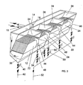
- a first embodiment of an arrangement according to the invention is designated generally by reference number 10.
- the arrangement 10 comprises a housing 12 which accommodates an inlet tank 14 for the liquid suspension to be cleaned.
- the liquid suspension which contains solid particles of extremely small dimensions (down to roughly 0.5 ⁇ m or even smaller), is supplied to the tank 14 continuously via a feed pipe 15.
- An overflow pipe 16 in an upper part of the tank 14 ensures that the liquid level in the tank is kept constant.
- these surface-creating, inclined elements consist of thin-walled tubular elements 32 of small diameter, for example roughly 3 mm.
- a respective decanting chamber 34 and 36 is located downstream of and above the sedimentation chambers 22, 24 in the housing 12 and is likewise delimited by said inner intermediate walls 17, 18 and outer walls 19, 20, 21.
- a sludge-collecting bottom trough 38 is formed in the housing 12.
- a bottom valve 40 can be opened when the sludge collected in the trough is to be emptied and led off via a sludge drain 42.
- An outlet 44, 46 leads cleaned liquid off from the respective decanting chambers 34, 36 to a common outlet line 52 via a respective openable and closable outlet valve 48, 50.
- a respective adjustable throttle valve 54, 56 can be coordinated with the outlet valves 48, 50 in order to make possible accurate individual adjustment of the liquid flow from the decanting chambers 34, 36.
- the arrangement 10 in Fig. 1 for continuous cleaning of a liquid suspension contaminated with fine particles functions as follows: a flow of contaminated liquid is fed to the tank 14 via the feed pipe 15.
- the overflow pipe 16 ensures that the free liquid surface is kept at the same constant level in both the inlet tank 14 and the decanting chambers 34, 36 communicating therewith.
- the outlet valves 48, 50 are kept closed, the liquid suspension flows from the tank 14 via the bottom trough 38 and the sedimentation tubes 32 up into the decanting chambers 34, 36 to the predetermined liquid level.
- the outlet valve 48 is closed at the same time as the outlet valve 50 for the other decanting chamber 36 is opened, this chamber slowly being emptied of cleaned liquid through the outlet 46 and simultaneously being filled with new liquid from below until the degree of contamination of the liquid flowing out has reached a permitted maximum level.
- the outlet valve 50 is closed at the same time as the outlet valve 48 is opened again.
- the outflows from the respective decanting chambers 34, 36 can be regulated in such a manner that sufficient dwell and sedimentation time is obtained for the liquid suspension in the closed decanting chamber at the same time as minimum movement takes place in the liquid in the chamber being emptied.
- Fig. 2 shows an alternative embodiment of a cleaning arrangement according to the present invention, which corresponds to the embodiment in Fig. 1 with the difference that, instead of tubular elements 32, use is made of plane, parallel lamellar plates 58 as particle-separating sedimentation elements.
- Fig. 3 shows another embodiment according to the invention, where the capacity of the cleaning arrangement has been increased by multiplying the number of sedimentation and decanting chambers 22, 24, 34, 36 to four.
- the inlet tank 14 is common to all these chambers.
- decanting can take place sequentially in steps or in pairs so that a continuous outflow of cleaned liquid can be obtained in the common outlet line 52.
- the number of chambers can of course be varied arbitrarily in order to suit the application concerned.
- Fig. 4 shows a side view of an alternative embodiment of a cleaning arrangement 60 according to the invention, which, at the same time as separation of fine solid particles, also makes possible continuous separation of a lighter liquid phase from a heavier liquid phase in a liquid suspension.
- the arrangement comprises a housing 62 which accommodates an inlet tank 64 for the liquid suspension to be cleaned.
- the liquid suspension which contains a heavier liquid phase, for example water, a lighter liquid phase, for example oil, and also fine solid particles, for example grinding particles originating from, for example, machining of glass material, is fed continuously to the tank 64 via a feed pipe 66.
- An overflow 68 with a return line 70 in the upper part of the tank 64 ensures a constant liquid level in the tank 64.
- At least two separate sedimentation chambers which are arranged parallel to the tank 64 and in each of which a particle-separating unit 72 in the form of a plurality of parallel, adjacent surface-creating elements inclined at a great angle to the horizontal, such as fine tubular elements or plane lamellar plates, is mounted, communicate with the inlet tank 64.
- a sludge-collecting bottom trough 74 is formed in the housing 62.
- a bottom valve 76 can be opened when the sludge collected in the trough is to be emptied and led off via a sludge drain 78.
- a chamber 80 immediately above and downstream of the particle-separating unit 72 in the housing 62 is delimited at the top by a light-phase-separating inclined top plate 82 which intercepts rising light-phase liquid, for example oil particles, in the liquid suspension and diverts it diagonally up to the left to a light-phase outlet 84, where it can run over into a collecting trough 86.
- the heavier liquid phase of the liquid suspension flowing out of the separating unit 72 flows up to a decanting chamber 88, located higher up and to the right in Fig. 4, where cleaned heavy-phase liquid can, in the same manner as in the embodiments in Figs 1-3, flow out alternately from each decanting chamber 88 via an outlet 90, when an outlet valve 92 arranged downstream of the outlet 90 is kept open.
- the flow from the outlet 90 to a common outlet line 95 can be finely regulated by means of a throttle valve 94.
- This embodiment therefore functions in the same way as the previous embodiments, apart from the fact that, in addition, a light-phase liquid can be separated from a heavier liquid phase.
- Fig. 5 shows a further embodiment of a cleaning arrangement according to the invention.
- the arrangement 96 comprises two entirely separate cleaning units 98, 100, each having its own inlet tank 102, sedimentation and decanting chambers 104 and, respectively, 106, a particle-separating unit 107 and a sludge collecting trough 108 in the same way as described above in the other embodiments.
- each feed line 110 is provided with an openable and closable valve 112 and, respectively, 114, while the outlets 116 from the decanting chambers 106 do not, for this reason, require any valves.
- the inlet tank 102 does not require its own overflow either in order to obtain the same liquid level in the inlet tank 102 and in the decanting chamber 106, as the admission opening 118 of the outlets 116 lies at the same level as the inlet opening 120 of the feed line 110.
- This embodiment also therefore makes possible cleaning of a continuous inflow of contaminated liquid suspension by alternately opening and closing the inlet valves 112, 114 in order in this way alternately to draw off cleaned liquid from the decanting chambers 106 to a common outlet line 52.
- emptying of a decanting chamber 106 begins when the requisite degree of cleanness of the liquid therein has been achieved and when the degree of contamination of the liquid flowing out of another cleaning unit 98 or 100 has risen to a maximum permitted value.
- This embodiment can also have an arbitrary number of separate cleaning arrangements, which are combined with one another in order to increase the capacity for separating microparticles, which are difficult to separate, from liquid suspensions.
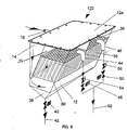
- Fig. 6 shows a further embodiment of an arrangement according to the invention for cleaning fine solid particles from a continuously flowing liquid suspension.
- This embodiment differs from those shown in Figs 1-4 in that it is made as a hermetically sealed unit 122 with a tightly fitting cover 124, mounted above the inlet tank 14 and the decanting chambers 34, 36.
- a pressure generator for example a motor-driven pump (not shown), which constantly keeps the inlet tank 14 and the decanting chambers 34, 36 completely filled and pressurized with liquid up to the cover 124.
- the decanting chambers 34, 36 are emptied alternately by the valve units 48, 50 associated with the outlets 44, 46 being opened and closed alternately with one another.
- the respective valve unit 48 and 50 is kept open for as long as it takes for a cleaned liquid volume, which corresponds to the liquid volume in the particle-separating unit 30, to leave the decanting chamber 34, 36 at a slow flow rate which does not disturb the particle sediment which is collected in the unit 30 and can fall down into the bottom trough 38 and is periodically emptied and led off via the sludge drain 42 when the bottom valve 40 is opened.
Landscapes
- Chemical & Material Sciences (AREA)
- Chemical Kinetics & Catalysis (AREA)
- Physics & Mathematics (AREA)
- Thermal Sciences (AREA)
- Engineering & Computer Science (AREA)
- Mechanical Engineering (AREA)
- Separation Of Solids By Using Liquids Or Pneumatic Power (AREA)
- Physical Or Chemical Processes And Apparatus (AREA)
- Glanulating (AREA)
Abstract
Description
- The present invention relates generally to cleaning liquid suspensions containing very fine solid particles, such as coolants containing, for example, solid particles originating from glass-grinding with a dimension down to roughly 0.5 µm, that is to say solid particles which are very difficult to separate from the liquid phase on account of their small size.
- More specifically, the invention relates to inter alia an arrangement for cleaning a continuously flowing liquid suspension of such a type, where the arrangement comprises an inlet tank, a feed pipe opening into the inlet tank for continuously supplying the liquid suspension to be cleaned, a sedimentation chamber unit located downstream of the inlet tank, a particle-separating unit which is located in the sedimentation chamber unit and contains a plurality of parallel, adjacent surface elements inclined at a great angle to the horizontal plane, at least two decanting chambers, located above and downstream of the sedimentation chamber unit, with an outlet for cleaned liquid, and a sediment sludge outlet located in a bottom portion of the sedimentation chamber unit.
- The invention also relates to an arrangement of equivalent type, where the arrangement comprises at least two separate inlet tanks, a feed pipe opening into each inlet tank for supplying the liquid suspension to be cleaned, a sedimentation chamber unit located downstream of each inlet tank, a particle-separating unit which is located in the sedimentation chamber unit and contains a plurality of parallel, adjacent surface elements inclined at a great angle to the horizontal plane, a decanting chamber, located above and downstream of the respective sedimentation chamber, with an outlet for cleaned liquid, and a sediment sludge outlet located in a bottom portion of the sedimentation chamber unit.
- The present invention also relates to methods of cleaning fine solid particles from a continuously flowing liquid suspension.
- The separation of very fine solid particles of a size of roughly 0.5 to 5 µm from liquid suspensions by sedimentation normally requires very long sedimentation times as the settling rate of the particles is very slow. This means that the particles must not be influenced by the flow of the liquid during sedimentation, which in practice means that effective sedimentation can be carried out only in a stationary liquid mass, as the particles are influenced by nothing other than the forces of gravity.
- SE-B-7509004-3, for example, describes an arrangement of the type described in the introduction for separating a lighter liquid phase together with heavier solid fractions from a heavier liquid phase of a liquid mixture. Such an arrangement would not, however, be capable of or suitable for continuous separation of very fine solid particles which are difficult to separate of the type referred to above on account of excessive disturbance caused by the liquid suspension flowing through.
- One object of the present invention is to produce an arrangement which makes possible effective continuous cleaning of a liquid suspension containing very fine particles, where the arrangement has relatively small dimensions and makes possible separation in a relatively short time. To this end, the arrangement according to the invention is characterized by the features indicated in the independent and dependent arrangement claims below.
- Another object of the present invention is to propose a method which makes possible effective continuous cleaning of a liquid suspension containing very fine particles in a relatively short time. To this end, the method according to the invention is characterized by the features indicated in the independent method claims below.
- Further objects and features of arrangements and methods according to the invention will emerge in greater detail from the detailed description given below with reference to accompanying drawing figures.
-
- Fig. 1 is a diagrammatic perspective view of a first embodiment of an arrangement according to the present invention;
- Fig. 2 is a view similar to Fig. 1 of a second embodiment of an arrangement according to the invention;
- Fig. 3 is a view similar to Fig. 1 of a third embodiment of an arrangement according to the invention;
- Fig. 4 is a diagrammatic side view of a fourth embodiment of an arrangement according to the invention;
- Fig. 5 is a perspective view of a fifth embodiment of an arrangement according to the invention, and
- Fig. 6 is a perspective view of a further embodiment of an arrangement according to the invention.
-
- In Fig. 1, a first embodiment of an arrangement according to the invention is designated generally by
reference number 10. Thearrangement 10 comprises ahousing 12 which accommodates aninlet tank 14 for the liquid suspension to be cleaned. The liquid suspension, which contains solid particles of extremely small dimensions (down to roughly 0.5 µm or even smaller), is supplied to thetank 14 continuously via afeed pipe 15. Anoverflow pipe 16 in an upper part of thetank 14 ensures that the liquid level in the tank is kept constant. Twosedimentation chambers intermediate walls outer side walls unit 30 in the form of a plurality of parallel, adjacent surface-creating elements inclined at a great angle to the horizontal plane is mounted, communicate with theinlet tank 14. In the embodiment according to Fig. 1, these surface-creating, inclined elements consist of thin-walledtubular elements 32 of small diameter, for example roughly 3 mm. A respectivedecanting chamber sedimentation chambers housing 12 and is likewise delimited by said innerintermediate walls outer walls unit 30 in eachsedimentation chamber bottom trough 38 is formed in thehousing 12. Abottom valve 40 can be opened when the sludge collected in the trough is to be emptied and led off via asludge drain 42. Anoutlet decanting chambers common outlet line 52 via a respective openable andclosable outlet valve adjustable throttle valve outlet valves decanting chambers - The
arrangement 10 in Fig. 1 for continuous cleaning of a liquid suspension contaminated with fine particles functions as follows: a flow of contaminated liquid is fed to thetank 14 via thefeed pipe 15. Theoverflow pipe 16 ensures that the free liquid surface is kept at the same constant level in both theinlet tank 14 and thedecanting chambers inlet tank 14, when theoutlet valves tank 14 via thebottom trough 38 and thesedimentation tubes 32 up into thedecanting chambers tubes 32 and in the bottom of thetrough 38, the liquid mass in thedecanting chambers outlet valve 48 and then allowing relatively slow emptying of thedecanting chamber 34 concerned via itsoutlet 44 until the degree of contamination of the new liquid mass simultaneously flowing into thedecanting chamber 34 has reached a predetermined maximum level at theoutlet 44, which corresponds approximately to the time when a liquid volume present in the separatingunit 30 has flowed out of theoutlet 44. At this time, theoutlet valve 48 is closed at the same time as theoutlet valve 50 for the otherdecanting chamber 36 is opened, this chamber slowly being emptied of cleaned liquid through theoutlet 46 and simultaneously being filled with new liquid from below until the degree of contamination of the liquid flowing out has reached a permitted maximum level. When this has happened, theoutlet valve 50 is closed at the same time as theoutlet valve 48 is opened again. By way of such alternate filling, cleaning and emptying of the liquid in thedecanting chambers common outlet line 52 while a simultaneous continuous inflow of contaminated liquid suspension into theinlet tank 14 takes place. By means of theadjustable throttle valves decanting chambers - Fig. 2 shows an alternative embodiment of a cleaning arrangement according to the present invention, which corresponds to the embodiment in Fig. 1 with the difference that, instead of
tubular elements 32, use is made of plane, parallellamellar plates 58 as particle-separating sedimentation elements. - Fig. 3 shows another embodiment according to the invention, where the capacity of the cleaning arrangement has been increased by multiplying the number of sedimentation and
decanting chambers inlet tank 14 is common to all these chambers. In this connection, decanting can take place sequentially in steps or in pairs so that a continuous outflow of cleaned liquid can be obtained in thecommon outlet line 52. The number of chambers can of course be varied arbitrarily in order to suit the application concerned. - Fig. 4 shows a side view of an alternative embodiment of a
cleaning arrangement 60 according to the invention, which, at the same time as separation of fine solid particles, also makes possible continuous separation of a lighter liquid phase from a heavier liquid phase in a liquid suspension. In the same manner as in the embodiments in Figs 1-3, the arrangement comprises ahousing 62 which accommodates aninlet tank 64 for the liquid suspension to be cleaned. The liquid suspension, which contains a heavier liquid phase, for example water, a lighter liquid phase, for example oil, and also fine solid particles, for example grinding particles originating from, for example, machining of glass material, is fed continuously to thetank 64 via afeed pipe 66. Anoverflow 68 with areturn line 70 in the upper part of thetank 64 ensures a constant liquid level in thetank 64. At least two separate sedimentation chambers, which are arranged parallel to thetank 64 and in each of which a particle-separatingunit 72 in the form of a plurality of parallel, adjacent surface-creating elements inclined at a great angle to the horizontal, such as fine tubular elements or plane lamellar plates, is mounted, communicate with theinlet tank 64. Upstream of and below the particle-separatingunit 72, a sludge-collectingbottom trough 74 is formed in thehousing 62. Abottom valve 76 can be opened when the sludge collected in the trough is to be emptied and led off via asludge drain 78. Achamber 80 immediately above and downstream of the particle-separatingunit 72 in thehousing 62 is delimited at the top by a light-phase-separatinginclined top plate 82 which intercepts rising light-phase liquid, for example oil particles, in the liquid suspension and diverts it diagonally up to the left to a light-phase outlet 84, where it can run over into a collectingtrough 86. The heavier liquid phase of the liquid suspension flowing out of the separatingunit 72 flows up to adecanting chamber 88, located higher up and to the right in Fig. 4, where cleaned heavy-phase liquid can, in the same manner as in the embodiments in Figs 1-3, flow out alternately from eachdecanting chamber 88 via anoutlet 90, when anoutlet valve 92 arranged downstream of theoutlet 90 is kept open. The flow from theoutlet 90 to acommon outlet line 95 can be finely regulated by means of athrottle valve 94. This embodiment therefore functions in the same way as the previous embodiments, apart from the fact that, in addition, a light-phase liquid can be separated from a heavier liquid phase. - Fig. 5 shows a further embodiment of a cleaning arrangement according to the invention. In this embodiment, the
arrangement 96 comprises two entirelyseparate cleaning units decanting chambers 104 and, respectively, 106, a particle-separatingunit 107 and a sludge collectingtrough 108 in the same way as described above in the other embodiments. In contrast to the other embodiments, eachfeed line 110 is provided with an openable andclosable valve 112 and, respectively, 114, while theoutlets 116 from thedecanting chambers 106 do not, for this reason, require any valves. The inlet tank 102 does not require its own overflow either in order to obtain the same liquid level in the inlet tank 102 and in thedecanting chamber 106, as the admission opening 118 of theoutlets 116 lies at the same level as the inlet opening 120 of thefeed line 110. This embodiment also therefore makes possible cleaning of a continuous inflow of contaminated liquid suspension by alternately opening and closing theinlet valves decanting chambers 106 to acommon outlet line 52. In this case also, emptying of a decantingchamber 106 begins when the requisite degree of cleanness of the liquid therein has been achieved and when the degree of contamination of the liquid flowing out of anothercleaning unit - Fig. 6 shows a further embodiment of an arrangement according to the invention for cleaning fine solid particles from a continuously flowing liquid suspension. This embodiment differs from those shown in Figs 1-4 in that it is made as a hermetically sealed
unit 122 with a tightlyfitting cover 124, mounted above theinlet tank 14 and the decantingchambers inlet tank 14 and at the same time to connect thefeed 15 to a pressure generator, for example a motor-driven pump (not shown), which constantly keeps theinlet tank 14 and the decantingchambers cover 124. In the same way as in the embodiments according to Figs 1-4, the decantingchambers valve units outlets respective valve unit unit 30, to leave the decantingchamber unit 30 and can fall down into thebottom trough 38 and is periodically emptied and led off via thesludge drain 42 when thebottom valve 40 is opened.
Claims (21)
- An arrangement for cleaning fine solid particles from a continuously flowing liquid suspension, comprising an inlet tank (14; 64), a feed pipe (15; 66) opening into the inlet tank (14; 64) for continuously supplying the liquid suspension to be cleaned, a sedimentation chamber unit (22, 24) located downstream of the inlet tank (14; 64), a particle-separating unit (30; 72) which is located in the sedimentation chamber unit and contains a plurality of parallel, adjacent surface elements (32; 58) inclined at a great angle to the horizontal plane, at least two decanting chambers (34, 36; 88), located above and downstream of the sedimentation chamber unit (22, 24), with an outlet (44, 46; 90) for cleaned liquid, and a sediment sludge outlet (42; 78) located in a bottom portion (38; 74) of the sedimentation chamber unit, wherein the sedimentation chamber unit comprises at least two sedimentation chambers (22, 24) which are separate from one another, are connected parallel to the inlet tank (14; 64) and each have their own decanting chamber, wherein valve units (48, 50, 54, 56; 92, 94), coordinated with separate outlets (44, 46; 90) from the respective decanting chambers (34, 36; 88), are arranged so as to be opened and closed alternately with one another, and wherein an overflow (16; 68) in the inlet tank (14; 64) is arranged so as to keep the liquid surface in the inlet tank (14; 64) and the separate decanting chambers (34, 36; 88) at the same or essentially the same constant level.
- The arrangement as claimed in claim 1, wherein each valve unit comprises a flow-regulating throttle valve (54, 56; 94).
- The arrangement as claimed in claim 1 or 2, wherein the outlets (44, 46; 90) from the decanting chambers (34, 36; 88) are interconnected downstream of the valve units (48, 50, 54, 56; 92, 94).
- The arrangement as claimed in any one of claims 1-3, wherein the surface elements consist of plane lamellar plates (58).
- The arrangement as claimed in any one of claims 1-3, wherein the surface elements consist of tightly packed tubes (32).
- The arrangement as claimed in any one of claims 1-5, wherein, for additional separation of a lighter liquid phase from a heavier liquid phase of the liquid suspension, each decanting chamber (88) has an inclined wall (82) which is located above the sedimentation chamber, lies below the liquid level in the decanting chamber (88) and, at the top, opens into a light-phase outlet (84).
- The arrangement as claimed in claim 6, wherein the inclined wall (82) forms a top of a primary chamber (80), located above the sedimentation chamber, of the decanting chamber (88) and inclines away from a secondary part, located at the side and higher up, of the decanting chamber (88), where the outlet (90) for the heavier liquid phase is located.
- An arrangement for cleaning fine solid particles from a continuously flowing liquid suspension, comprising at least two separate inlet tanks (102), a feed pipe (110) opening into each inlet tank for supplying the liquid suspension to be cleaned, a sedimentation chamber (104) located downstream of each inlet tank (102), a particle-separating unit (107) which is located in the sedimentation chamber (104) and contains a plurality of parallel, adjacent surface elements inclined at a great angle to the horizontal plane, a decanting chamber (106), located above and downstream of the respective sedimentation chamber, with an outlet (116) for cleaned liquid, and a sediment sludge outlet (42) located in a bottom portion (108) of the sedimentation chamber, wherein valve units (112, 114), coordinated with the respective feeds (110) to the inlet tanks (102), are arranged so as to be opened and closed alternately with one another, and wherein the outlets (116) from the decanting chambers (106) have an admission opening (118) in an upper portion of the respective decanting chamber (106) and on a level with an inlet opening (120) of the respective feed (110).
- The arrangement as claimed in claim 8, wherein each valve unit comprises a flow-regulating throttle valve.
- The arrangement as claimed in claim 8 or 9, wherein the feeds (110) to the inlet tanks (102) are interconnected upstream of the valve units (112, 114).
- The arrangement as claimed in any one of claims 8-10, wherein the surface elements consist of plane lamellar plates.
- The arrangement as claimed in any one of claims 8-10, wherein the surface elements consist of tightly packed tubes.
- A method of cleaning fine solid particles from a continuously flowing liquid suspension, which comprises the stepsa) leading the continuously flowing liquid suspension to an inlet tank (14; 64),b) making the liquid suspension in the inlet tank (14; 64) flow slowly and alternately to and through at least two sedimentation chambers (22, 24) which are separate from one another, connected parallel to and downstream of the inlet tank and in which a particle-separating unit (30; 72) containing a plurality of parallel, adjacent surface elements (32; 58) inclined at a great angle to the horizontal plane is arranged, and then to a decanting chamber (34, 36; 88) located above and downstream of the respective sedimentation chamber (22, 24),c) a liquid level which is constant and essentially the same being maintained in the inlet tank (14; 64) and in the decanting chambers (34, 36; 88), andd) the alternate flow of liquid suspension to the sedimentation chambers (22, 24) being brought about by alternately opening and closing valve units (48, 50; 92) coordinated with separate outlets (44, 46; 90) from the respective decanting chambers (34, 36; 88).
- A method of cleaning fine solid particles from a continuously flowing liquid suspension, which comprises the steps:a) leading the continuously flowing liquid suspension alternately to at least two separate inlet tanks (102),b) making the liquid suspension in the inlet tanks flow slowly and alternately to and through a sedimentation chamber (104) which is connected downstream of each inlet tank (102) and in which a particle-separating unit (107) containing a plurality of parallel, adjacent surface elements inclined at a great angle to the horizontal plane is arranged, and then to a decanting chamber (106) located above and downstream of the respective sedimentation chamber (104),c) a liquid level which is constant and essentially the same being maintained in the respective inlet tanks (102) and in the decanting chambers (106), andd) the alternate flow of liquid suspension to the sedimentation chambers (104) being brought about by alternately opening and closing a valve unit (112, 114) in the respective feed (110) to each inlet tank (102).
- A method of cleaning fine solid particles from a continuously flowing liquid suspension, which comprises the stepsa) leading the continuously flowing liquid suspension to a hermetically sealed inlet tank (14) in order to fill the latter completely,b) making the liquid suspension in the inlet tank (14) flow slowly and alternately to and through at least two sedimentation chambers which are separate from one another, connected parallel to and downstream of the inlet tank and in which a particle-separating unit (30) containing a plurality of parallel, adjacent surface elements inclined at a great angle to the horizontal plane is arranged, and then to a hermetically sealed decanting chamber (34, 36) located above and downstream of the respective sedimentation chamber,c) the decanting chambers (34, 36) being filled in their entirety with cleaned liquid, andd) the alternate flow of liquid suspension to the sedimentation chambers being brought about by alternately opening and closing valve units (48, 50) coordinated with separate outlets (44, 46) from the respective decanting chambers (34, 36).
- An arrangement for cleaning fine solid particles from a continuously flowing liquid suspension, comprising an inlet tank (14), a feed pipe (15) opening into the inlet tank (14) for continuously supplying the liquid suspension to be cleaned, a sedimentation chamber unit located downstream of the inlet tank (14), a particle-separating unit (30) which is located in the sedimentation chamber unit and contains a plurality of parallel, adjacent surface elements inclined at a great angle to the horizontal plane, at least two decanting chambers (34, 36), located above and downstream of the sedimentation chamber unit, with an outlet (44, 46) for cleaned liquid, and a sediment sludge outlet (42) located in a bottom portion (38) of the sedimentation chamber unit, wherein the sedimentation chamber unit comprises at least two sedimentation chambers (22, 24) which are separate from one another, are connected parallel to the inlet tank (14) and each have their own decanting chamber, wherein valve units (48, 50, 54, 56), coordinated with separate outlets (44, 46) from the respective decanting chambers (34, 36), are arranged so as to be opened and closed alternately with one another, and wherein the inlet tank (14) and the sedimentation chamber unit are hermetically sealed in order to be kept completely filled with liquid.
- The arrangement as claimed in claim 16, wherein the inlet tank (14) and the decanting chambers (34, 36) have a common top wall (124).
- The arrangement as claimed in claim 16 or 17, wherein each valve unit comprises a flow-regulating throttle valve (54, 56).
- The arrangement as claimed in any one of claims 16-18, wherein the outlets (44, 46) from the decanting chambers (34, 36) are interconnected downstream of the valve units (48, 50, 54, 56).
- The arrangement as claimed in any one of claims 16-19, wherein the surface elements consist of plane lamellar plates.
- The arrangement as claimed in any one of claims 16-19, wherein the surface elements consist of tightly packed tubes.
Applications Claiming Priority (4)
| Application Number | Priority Date | Filing Date | Title |
|---|---|---|---|
| SE0101684A SE0101684D0 (en) | 2001-05-14 | 2001-05-14 | Device and method for decanting particles in a continuously flowing liquid stream |
| SE0101684 | 2001-05-14 | ||
| SE0103096 | 2001-09-18 | ||
| SE0103096A SE519052C2 (en) | 2001-05-14 | 2001-09-18 | Apparatus and method for purifying a continuously flowing liquid suspension from fine solid particles |
Publications (2)
| Publication Number | Publication Date |
|---|---|
| EP1260259A1 true EP1260259A1 (en) | 2002-11-27 |
| EP1260259B1 EP1260259B1 (en) | 2006-12-27 |
Family
ID=26655460
Family Applications (1)
| Application Number | Title | Priority Date | Filing Date |
|---|---|---|---|
| EP02010307A Expired - Lifetime EP1260259B1 (en) | 2001-05-14 | 2002-05-07 | Arrangement and method for cleaning fine solid particles from a continuously flowing liquid suspension |
Country Status (7)
| Country | Link |
|---|---|
| US (1) | US6923872B2 (en) |
| EP (1) | EP1260259B1 (en) |
| AT (1) | ATE349254T1 (en) |
| DE (1) | DE60217014T2 (en) |
| DK (1) | DK1260259T3 (en) |
| ES (1) | ES2277971T3 (en) |
| SE (1) | SE519052C2 (en) |
Cited By (3)
| Publication number | Priority date | Publication date | Assignee | Title |
|---|---|---|---|---|
| ITMI20100018A1 (en) * | 2010-01-12 | 2011-07-13 | Ecografica S R L | PLANT FOR THE SEPARATION AND RECOVERY OF MICROPARTELS CONTAINED IN SUSPENSION IN THE OFFSET PRINTING WATER. |
| WO2013026869A1 (en) * | 2011-08-23 | 2013-02-28 | Holger Blum | Contact filter device for separating suspended matter from water |
| CN108771888A (en) * | 2018-06-08 | 2018-11-09 | 中石化石油机械股份有限公司研究院 | Modularization is returned de- be fixedly mounted with of drain sedimentation and is set |
Families Citing this family (10)
| Publication number | Priority date | Publication date | Assignee | Title |
|---|---|---|---|---|
| DE102012219184A1 (en) | 2012-10-22 | 2014-05-08 | Krones Aktiengesellschaft | Device for the thermal treatment of products with cleaning of the process fluid |
| US12064712B2 (en) * | 2012-11-20 | 2024-08-20 | Newterra Ltd. | Water treatment apparatus and method of use |
| CA2833496C (en) * | 2012-11-20 | 2016-10-11 | Newterra Limited | Water treatment apparatus and method of use |
| CN103286102B (en) * | 2013-05-14 | 2015-04-08 | 泰兴市睿济科技有限公司 | Method of flushing inclined tubes in inclined-tube sedimentation basin |
| US10029190B2 (en) | 2015-06-20 | 2018-07-24 | Pacific Petroleum Recovery Alaska, Llc | Oil-water separator |
| US9993747B2 (en) * | 2015-09-01 | 2018-06-12 | Meurer Research, Inc. | Plate settler cover and method |
| CN107638720A (en) * | 2016-11-24 | 2018-01-30 | 重集团大连设计研究院有限公司 | A kind of energy-saving seawater desalinates water intake system |
| CN111888805A (en) * | 2020-08-26 | 2020-11-06 | 长沙矿山研究院有限责任公司 | Paste storage thickener and thickening process |
| CN112933669A (en) * | 2021-01-30 | 2021-06-11 | 连云港格瑞智慧能源科技有限公司 | Stationary flow sedimentation separation system |
| FR3124405B1 (en) * | 2021-06-25 | 2023-06-16 | Fives Dms | Rolling oil recycling and filtration plant and process |
Citations (5)
| Publication number | Priority date | Publication date | Assignee | Title |
|---|---|---|---|---|
| US4123365A (en) * | 1974-08-14 | 1978-10-31 | Ballast-Nedam Groep N.V. | Oil-water separator |
| US5049278A (en) * | 1989-08-30 | 1991-09-17 | Samdor Engineering | Modular plate settler |
| DE4119549A1 (en) * | 1990-07-28 | 1992-02-06 | Bernhard Kessel | Emptying of liq. separators, in separator system - where water is pumped from one separator into another operating in parallel, before first separator is emptied of sepd. material |
| US5536409A (en) * | 1994-10-25 | 1996-07-16 | Citec International Incorporated | Water treatment system |
| US6190554B1 (en) * | 1998-03-04 | 2001-02-20 | Mikkel G. Mandt | Surge anoxic mix sequencing batch reactor systems |
Family Cites Families (15)
| Publication number | Priority date | Publication date | Assignee | Title |
|---|---|---|---|---|
| US863168A (en) * | 1906-01-17 | 1907-08-13 | Ontario Nickel Company Ltd | Means for use in separating the more soluble constituents of a material from the less soluble constituents thereof. |
| SE330151B (en) * | 1968-09-20 | 1970-11-09 | Nordstjernan Rederi Ab | |
| US3862033A (en) * | 1969-05-22 | 1975-01-21 | Separa Brno Inzenyrska Kancela | Method for sedimentation of solid impurities from liquids |
| SE356435B (en) * | 1969-08-08 | 1973-05-28 | Hane G Weijman | |
| FR2223065B2 (en) * | 1972-08-25 | 1976-06-11 | Degremont | |
| DE3002417C2 (en) * | 1979-03-26 | 1984-12-20 | Novex Találmányfejlesztö és Ertékesítö Külkereskedelmi Rt., Budapest | Lamella separator for liquids |
| DE3043254A1 (en) * | 1980-11-15 | 1982-07-08 | Robert Bosch Gmbh, 7000 Stuttgart | METHOD FOR CLEANING NEUTRALIZED INDUSTRIAL WASTEWATER AND DEVICE FOR IMPLEMENTING THE METHOD |
| US4595504A (en) * | 1982-05-06 | 1986-06-17 | Sfs Swede Filter System, Inc. | Lamella sedimentation device |
| DE3734881A1 (en) * | 1987-10-15 | 1989-04-27 | Rhodia Ag | METHOD AND DEVICE FOR SEPARATING COARSE-GRINED AND AGGLOMERED PIGMENT PARTICLES FROM A SUSPENSION CONTAINING COARSE-Grained, AGGLOMERED AND FINE-GRAINED PIGMENT PARTICLES |
| FR2699421B1 (en) * | 1992-12-21 | 1995-02-10 | Alsthom Gec | Lamellar settling tank with double flow. |
| SE503301C2 (en) * | 1995-03-20 | 1996-05-13 | Vivex Ab | Method and apparatus for gravity separation of fine particles from a liquid |
| US5554301A (en) * | 1995-05-08 | 1996-09-10 | Universal Environmental Technologies, Inc. | Water clarification system |
| MX9604952A (en) * | 1996-10-18 | 1998-04-30 | Servicios Condumex Sa | Solid particles hydraulic classifier and reactor with ultrasound application. |
| CA2243580A1 (en) * | 1998-07-24 | 2000-01-24 | Richard H. Chilibeck | Apparatus and process for removing fine metallic particles from effluent liquid waste |
| US6676832B2 (en) * | 2002-01-05 | 2004-01-13 | Terre Hill Silo Company | Surface water purifying catch basin |
-
2001
- 2001-09-18 SE SE0103096A patent/SE519052C2/en not_active IP Right Cessation
-
2002
- 2002-05-07 EP EP02010307A patent/EP1260259B1/en not_active Expired - Lifetime
- 2002-05-07 DE DE60217014T patent/DE60217014T2/en not_active Expired - Fee Related
- 2002-05-07 AT AT02010307T patent/ATE349254T1/en not_active IP Right Cessation
- 2002-05-07 ES ES02010307T patent/ES2277971T3/en not_active Expired - Lifetime
- 2002-05-07 DK DK02010307T patent/DK1260259T3/en active
- 2002-05-13 US US10/142,947 patent/US6923872B2/en not_active Expired - Fee Related
Patent Citations (5)
| Publication number | Priority date | Publication date | Assignee | Title |
|---|---|---|---|---|
| US4123365A (en) * | 1974-08-14 | 1978-10-31 | Ballast-Nedam Groep N.V. | Oil-water separator |
| US5049278A (en) * | 1989-08-30 | 1991-09-17 | Samdor Engineering | Modular plate settler |
| DE4119549A1 (en) * | 1990-07-28 | 1992-02-06 | Bernhard Kessel | Emptying of liq. separators, in separator system - where water is pumped from one separator into another operating in parallel, before first separator is emptied of sepd. material |
| US5536409A (en) * | 1994-10-25 | 1996-07-16 | Citec International Incorporated | Water treatment system |
| US6190554B1 (en) * | 1998-03-04 | 2001-02-20 | Mikkel G. Mandt | Surge anoxic mix sequencing batch reactor systems |
Cited By (6)
| Publication number | Priority date | Publication date | Assignee | Title |
|---|---|---|---|---|
| ITMI20100018A1 (en) * | 2010-01-12 | 2011-07-13 | Ecografica S R L | PLANT FOR THE SEPARATION AND RECOVERY OF MICROPARTELS CONTAINED IN SUSPENSION IN THE OFFSET PRINTING WATER. |
| WO2013026869A1 (en) * | 2011-08-23 | 2013-02-28 | Holger Blum | Contact filter device for separating suspended matter from water |
| GB2508534A (en) * | 2011-08-23 | 2014-06-04 | Holger Blum | Contact filter device for separating suspended matter from water |
| ES2491366R1 (en) * | 2011-08-23 | 2015-03-31 | Holger Blum | CONTACT FILTER DEVICE FOR SEPARATING SUSPENDED SUBJECTS IN WATER |
| CN108771888A (en) * | 2018-06-08 | 2018-11-09 | 中石化石油机械股份有限公司研究院 | Modularization is returned de- be fixedly mounted with of drain sedimentation and is set |
| CN108771888B (en) * | 2018-06-08 | 2020-09-29 | 中石化石油机械股份有限公司研究院 | Modular backflow liquid sedimentation and separation solid device |
Also Published As
| Publication number | Publication date |
|---|---|
| SE519052C2 (en) | 2003-01-07 |
| US6923872B2 (en) | 2005-08-02 |
| SE0103096L (en) | 2002-11-15 |
| EP1260259B1 (en) | 2006-12-27 |
| ATE349254T1 (en) | 2007-01-15 |
| DE60217014T2 (en) | 2007-07-05 |
| DK1260259T3 (en) | 2007-04-30 |
| DE60217014D1 (en) | 2007-02-08 |
| ES2277971T3 (en) | 2007-08-01 |
| SE0103096D0 (en) | 2001-09-18 |
| US20020166576A1 (en) | 2002-11-14 |
Similar Documents
| Publication | Publication Date | Title |
|---|---|---|
| US6923872B2 (en) | Arrangement and method for cleaning fine solid particles from a continuously flowing liquid suspension | |
| RU2241519C2 (en) | Device for separation of liquid mixtures | |
| CN107349637B (en) | Gas flotation tank | |
| HU190719B (en) | Apparatus for vortex separating liquids of different thickness | |
| CA2419217A1 (en) | Separators for three-phase or two-phase fluid mixtures realized with a centrifugal device designed for the separation of the gas from the liquid mixture | |
| US3862039A (en) | Gravity oil-water separator with two interconnected singular cells having automatic free oil discharge | |
| US1176775A (en) | Separator. | |
| EP1268025B1 (en) | Method and apparatus for separation of a mixture of non-miscible liquids | |
| US4544487A (en) | Clarifier/thickener | |
| US3744643A (en) | Suspension clearing treatment device | |
| EP1296771B1 (en) | Dual-cell mechanical flotation system | |
| US1709971A (en) | Liquid separator | |
| US2414176A (en) | Sludge settling and dewatering tank | |
| CN208200542U (en) | Oil water separator | |
| CN209155188U (en) | A kind of antodischarging oil oily-water seperating equipment | |
| US2220925A (en) | Separation of materials of different specific gravities | |
| CN216785857U (en) | Floating oil type oil-water automatic separating device | |
| US3197336A (en) | Clarifiers and separators | |
| US322817A (en) | g-arrett | |
| SU776543A3 (en) | Feeding device to hydrocyclone | |
| KR20160146454A (en) | Separator for mixed liquid | |
| US20050016938A1 (en) | Filtering apparatus | |
| CN207210029U (en) | A kind of multistage oil interceptor for exempting from regulation | |
| RU2101070C1 (en) | Water treatment plant | |
| JPH01258788A (en) | Method and device for separating oil and water |
Legal Events
| Date | Code | Title | Description |
|---|---|---|---|
| PUAI | Public reference made under article 153(3) epc to a published international application that has entered the european phase |
Free format text: ORIGINAL CODE: 0009012 |
|
| AK | Designated contracting states |
Kind code of ref document: A1 Designated state(s): AT BE CH CY DE DK ES FI FR GB GR IE IT LI LU MC NL PT SE TR |
|
| AX | Request for extension of the european patent |
Free format text: AL;LT;LV;MK;RO;SI |
|
| 17P | Request for examination filed |
Effective date: 20030502 |
|
| AKX | Designation fees paid |
Designated state(s): AT BE CH CY DE DK ES FI FR GB GR IE IT LI LU MC NL PT SE TR |
|
| 17Q | First examination report despatched |
Effective date: 20031218 |
|
| GRAP | Despatch of communication of intention to grant a patent |
Free format text: ORIGINAL CODE: EPIDOSNIGR1 |
|
| GRAS | Grant fee paid |
Free format text: ORIGINAL CODE: EPIDOSNIGR3 |
|
| GRAA | (expected) grant |
Free format text: ORIGINAL CODE: 0009210 |
|
| AK | Designated contracting states |
Kind code of ref document: B1 Designated state(s): AT BE CH CY DE DK ES FI FR GB GR IE IT LI LU MC NL PT SE TR |
|
| PG25 | Lapsed in a contracting state [announced via postgrant information from national office to epo] |
Ref country code: IT Free format text: LAPSE BECAUSE OF FAILURE TO SUBMIT A TRANSLATION OF THE DESCRIPTION OR TO PAY THE FEE WITHIN THE PRESCRIBED TIME-LIMIT;WARNING: LAPSES OF ITALIAN PATENTS WITH EFFECTIVE DATE BEFORE 2007 MAY HAVE OCCURRED AT ANY TIME BEFORE 2007. THE CORRECT EFFECTIVE DATE MAY BE DIFFERENT FROM THE ONE RECORDED. Effective date: 20061227 Ref country code: CH Free format text: LAPSE BECAUSE OF FAILURE TO SUBMIT A TRANSLATION OF THE DESCRIPTION OR TO PAY THE FEE WITHIN THE PRESCRIBED TIME-LIMIT Effective date: 20061227 Ref country code: AT Free format text: LAPSE BECAUSE OF FAILURE TO SUBMIT A TRANSLATION OF THE DESCRIPTION OR TO PAY THE FEE WITHIN THE PRESCRIBED TIME-LIMIT Effective date: 20061227 Ref country code: NL Free format text: LAPSE BECAUSE OF FAILURE TO SUBMIT A TRANSLATION OF THE DESCRIPTION OR TO PAY THE FEE WITHIN THE PRESCRIBED TIME-LIMIT Effective date: 20061227 Ref country code: LI Free format text: LAPSE BECAUSE OF FAILURE TO SUBMIT A TRANSLATION OF THE DESCRIPTION OR TO PAY THE FEE WITHIN THE PRESCRIBED TIME-LIMIT Effective date: 20061227 Ref country code: BE Free format text: LAPSE BECAUSE OF FAILURE TO SUBMIT A TRANSLATION OF THE DESCRIPTION OR TO PAY THE FEE WITHIN THE PRESCRIBED TIME-LIMIT Effective date: 20061227 |
|
| REG | Reference to a national code |
Ref country code: GB Ref legal event code: FG4D |
|
| REG | Reference to a national code |
Ref country code: IE Ref legal event code: FG4D |
|
| REF | Corresponds to: |
Ref document number: 60217014 Country of ref document: DE Date of ref document: 20070208 Kind code of ref document: P |
|
| PG25 | Lapsed in a contracting state [announced via postgrant information from national office to epo] |
Ref country code: SE Free format text: LAPSE BECAUSE OF FAILURE TO SUBMIT A TRANSLATION OF THE DESCRIPTION OR TO PAY THE FEE WITHIN THE PRESCRIBED TIME-LIMIT Effective date: 20070327 |
|
| ET | Fr: translation filed | ||
| REG | Reference to a national code |
Ref country code: DK Ref legal event code: T3 |
|
| PG25 | Lapsed in a contracting state [announced via postgrant information from national office to epo] |
Ref country code: PT Free format text: LAPSE BECAUSE OF FAILURE TO SUBMIT A TRANSLATION OF THE DESCRIPTION OR TO PAY THE FEE WITHIN THE PRESCRIBED TIME-LIMIT Effective date: 20070528 |
|
| NLV1 | Nl: lapsed or annulled due to failure to fulfill the requirements of art. 29p and 29m of the patents act | ||
| REG | Reference to a national code |
Ref country code: CH Ref legal event code: PL |
|
| REG | Reference to a national code |
Ref country code: ES Ref legal event code: FG2A Ref document number: 2277971 Country of ref document: ES Kind code of ref document: T3 |
|
| PLBE | No opposition filed within time limit |
Free format text: ORIGINAL CODE: 0009261 |
|
| STAA | Information on the status of an ep patent application or granted ep patent |
Free format text: STATUS: NO OPPOSITION FILED WITHIN TIME LIMIT |
|
| 26N | No opposition filed |
Effective date: 20070928 |
|
| PG25 | Lapsed in a contracting state [announced via postgrant information from national office to epo] |
Ref country code: MC Free format text: LAPSE BECAUSE OF NON-PAYMENT OF DUE FEES Effective date: 20070531 |
|
| PG25 | Lapsed in a contracting state [announced via postgrant information from national office to epo] |
Ref country code: GR Free format text: LAPSE BECAUSE OF FAILURE TO SUBMIT A TRANSLATION OF THE DESCRIPTION OR TO PAY THE FEE WITHIN THE PRESCRIBED TIME-LIMIT Effective date: 20070328 |
|
| PG25 | Lapsed in a contracting state [announced via postgrant information from national office to epo] |
Ref country code: IE Free format text: LAPSE BECAUSE OF NON-PAYMENT OF DUE FEES Effective date: 20070508 |
|
| PGFP | Annual fee paid to national office [announced via postgrant information from national office to epo] |
Ref country code: DE Payment date: 20080522 Year of fee payment: 7 Ref country code: ES Payment date: 20080526 Year of fee payment: 7 Ref country code: DK Payment date: 20080526 Year of fee payment: 7 |
|
| PGFP | Annual fee paid to national office [announced via postgrant information from national office to epo] |
Ref country code: FI Payment date: 20080522 Year of fee payment: 7 |
|
| PGFP | Annual fee paid to national office [announced via postgrant information from national office to epo] |
Ref country code: GB Payment date: 20080522 Year of fee payment: 7 |
|
| PG25 | Lapsed in a contracting state [announced via postgrant information from national office to epo] |
Ref country code: LU Free format text: LAPSE BECAUSE OF NON-PAYMENT OF DUE FEES Effective date: 20070507 Ref country code: CY Free format text: LAPSE BECAUSE OF FAILURE TO SUBMIT A TRANSLATION OF THE DESCRIPTION OR TO PAY THE FEE WITHIN THE PRESCRIBED TIME-LIMIT Effective date: 20061227 |
|
| PG25 | Lapsed in a contracting state [announced via postgrant information from national office to epo] |
Ref country code: TR Free format text: LAPSE BECAUSE OF FAILURE TO SUBMIT A TRANSLATION OF THE DESCRIPTION OR TO PAY THE FEE WITHIN THE PRESCRIBED TIME-LIMIT Effective date: 20061227 |
|
| REG | Reference to a national code |
Ref country code: DK Ref legal event code: EBP |
|
| GBPC | Gb: european patent ceased through non-payment of renewal fee |
Effective date: 20090507 |
|
| PG25 | Lapsed in a contracting state [announced via postgrant information from national office to epo] |
Ref country code: FI Free format text: LAPSE BECAUSE OF NON-PAYMENT OF DUE FEES Effective date: 20090507 |
|
| REG | Reference to a national code |
Ref country code: FR Ref legal event code: ST Effective date: 20100129 |
|
| PG25 | Lapsed in a contracting state [announced via postgrant information from national office to epo] |
Ref country code: FR Free format text: LAPSE BECAUSE OF NON-PAYMENT OF DUE FEES Effective date: 20090602 Ref country code: DK Free format text: LAPSE BECAUSE OF NON-PAYMENT OF DUE FEES Effective date: 20090531 |
|
| PGFP | Annual fee paid to national office [announced via postgrant information from national office to epo] |
Ref country code: FR Payment date: 20080430 Year of fee payment: 7 |
|
| PG25 | Lapsed in a contracting state [announced via postgrant information from national office to epo] |
Ref country code: GB Free format text: LAPSE BECAUSE OF NON-PAYMENT OF DUE FEES Effective date: 20090507 |
|
| PG25 | Lapsed in a contracting state [announced via postgrant information from national office to epo] |
Ref country code: DE Free format text: LAPSE BECAUSE OF NON-PAYMENT OF DUE FEES Effective date: 20091201 |
|
| REG | Reference to a national code |
Ref country code: ES Ref legal event code: FD2A Effective date: 20090508 |
|
| PG25 | Lapsed in a contracting state [announced via postgrant information from national office to epo] |
Ref country code: ES Free format text: LAPSE BECAUSE OF NON-PAYMENT OF DUE FEES Effective date: 20090508 |