EP1259427B1 - A method and apparatus for packaging ultra fine powders into containers - Google Patents
A method and apparatus for packaging ultra fine powders into containers Download PDFInfo
- Publication number
- EP1259427B1 EP1259427B1 EP01907936A EP01907936A EP1259427B1 EP 1259427 B1 EP1259427 B1 EP 1259427B1 EP 01907936 A EP01907936 A EP 01907936A EP 01907936 A EP01907936 A EP 01907936A EP 1259427 B1 EP1259427 B1 EP 1259427B1
- Authority
- EP
- European Patent Office
- Prior art keywords
- container
- port
- chamber
- valve
- gate member
- Prior art date
- Legal status (The legal status is an assumption and is not a legal conclusion. Google has not performed a legal analysis and makes no representation as to the accuracy of the status listed.)
- Expired - Lifetime
Links
- 239000000843 powder Substances 0.000 title claims description 48
- 238000000034 method Methods 0.000 title claims description 19
- 238000004806 packaging method and process Methods 0.000 title claims description 6
- 238000010926 purge Methods 0.000 claims description 15
- 238000004519 manufacturing process Methods 0.000 claims description 5
- 238000007789 sealing Methods 0.000 claims description 5
- 230000000295 complement effect Effects 0.000 claims description 4
- 239000007789 gas Substances 0.000 description 12
- 239000011261 inert gas Substances 0.000 description 7
- 239000000463 material Substances 0.000 description 3
- 239000004744 fabric Substances 0.000 description 2
- MCMNRKCIXSYSNV-UHFFFAOYSA-N ZrO2 Inorganic materials O=[Zr]=O MCMNRKCIXSYSNV-UHFFFAOYSA-N 0.000 description 1
- 230000000712 assembly Effects 0.000 description 1
- 238000000429 assembly Methods 0.000 description 1
- QVGXLLKOCUKJST-UHFFFAOYSA-N atomic oxygen Chemical compound [O] QVGXLLKOCUKJST-UHFFFAOYSA-N 0.000 description 1
- 238000010923 batch production Methods 0.000 description 1
- 238000010276 construction Methods 0.000 description 1
- 239000012530 fluid Substances 0.000 description 1
- 230000005484 gravity Effects 0.000 description 1
- 239000001301 oxygen Substances 0.000 description 1
- 229910052760 oxygen Inorganic materials 0.000 description 1
- 239000002245 particle Substances 0.000 description 1
- 239000007787 solid Substances 0.000 description 1
- 238000000527 sonication Methods 0.000 description 1
- 230000003068 static effect Effects 0.000 description 1
Images

Classifications
-
- B—PERFORMING OPERATIONS; TRANSPORTING
- B65—CONVEYING; PACKING; STORING; HANDLING THIN OR FILAMENTARY MATERIAL
- B65B—MACHINES, APPARATUS OR DEVICES FOR, OR METHODS OF, PACKAGING ARTICLES OR MATERIALS; UNPACKING
- B65B31/00—Packaging articles or materials under special atmospheric or gaseous conditions; Adding propellants to aerosol containers
- B65B31/02—Filling, closing, or filling and closing, containers or wrappers in chambers maintained under vacuum or superatmospheric pressure or containing a special atmosphere, e.g. of inert gas
-
- B—PERFORMING OPERATIONS; TRANSPORTING
- B65—CONVEYING; PACKING; STORING; HANDLING THIN OR FILAMENTARY MATERIAL
- B65G—TRANSPORT OR STORAGE DEVICES, e.g. CONVEYORS FOR LOADING OR TIPPING, SHOP CONVEYOR SYSTEMS OR PNEUMATIC TUBE CONVEYORS
- B65G69/00—Auxiliary measures taken, or devices used, in connection with loading or unloading
- B65G69/18—Preventing escape of dust
- B65G69/181—Preventing escape of dust by means of sealed systems
- B65G69/183—Preventing escape of dust by means of sealed systems with co-operating closure members on each of the parts of a separable transfer channel
-
- B—PERFORMING OPERATIONS; TRANSPORTING
- B65—CONVEYING; PACKING; STORING; HANDLING THIN OR FILAMENTARY MATERIAL
- B65B—MACHINES, APPARATUS OR DEVICES FOR, OR METHODS OF, PACKAGING ARTICLES OR MATERIALS; UNPACKING
- B65B31/00—Packaging articles or materials under special atmospheric or gaseous conditions; Adding propellants to aerosol containers
- B65B31/02—Filling, closing, or filling and closing, containers or wrappers in chambers maintained under vacuum or superatmospheric pressure or containing a special atmosphere, e.g. of inert gas
- B65B31/025—Filling, closing, or filling and closing, containers or wrappers in chambers maintained under vacuum or superatmospheric pressure or containing a special atmosphere, e.g. of inert gas specially adapted for rigid or semi-rigid containers
-
- B—PERFORMING OPERATIONS; TRANSPORTING
- B65—CONVEYING; PACKING; STORING; HANDLING THIN OR FILAMENTARY MATERIAL
- B65B—MACHINES, APPARATUS OR DEVICES FOR, OR METHODS OF, PACKAGING ARTICLES OR MATERIALS; UNPACKING
- B65B39/00—Nozzles, funnels or guides for introducing articles or materials into containers or wrappers
- B65B39/001—Nozzles, funnels or guides for introducing articles or materials into containers or wrappers with flow cut-off means, e.g. valves
- B65B39/004—Nozzles, funnels or guides for introducing articles or materials into containers or wrappers with flow cut-off means, e.g. valves moving linearly
- B65B39/005—Nozzles, funnels or guides for introducing articles or materials into containers or wrappers with flow cut-off means, e.g. valves moving linearly transverse to flow direction
Definitions
- the present invention relates to a method and apparatus for packaging ultra fine powders into containers.
- Ultra fine powders of less than 1 micron in unit dimension and particularly nanometric powders of less than 100 nanometres unit dimension have a high surface area to weight ratio. Due to the high surface energy the powders are easily contaminated and in some cases react vigorously with air. In order to keep the powders in an as-produced form it is necessary to store them in an unreactive medium such as inert gas and other fluid media.
- the present invention provides a way in which the powders can be cleared from the reaction production apparatus in a non-reactive environment and in a manner that is repeatable and suitable for mass production.
- US 5263521 discloses a method for packaging ultra fine powders into containers in a controlled environment in a sealed apparatus in which the internal environment does not react with the powder and which comprises a powder delivery chamber to which a supply of the powder is supplied from the reaction production apparatus, the powder delivery chamber having a port for receiving a container, the port being selectively closable by a first valve which seals the port, wherein each container is closable by a second valve which seals the container; the method comprising the steps of closing the first valve to seal the port; attaching a container to the port; opening the first valve; with the second valve also open, introducing powder into the container; closing the first and second valves to seal the port and the container; and disconnecting the container from the port.
- such a method is characterised in that the lowermost part of the powder delivery chamber is housed within a loading chamber, and the method further comprises loading a container into the loading chamber, and purging the loading chamber and hence the container.
- the use of the two valves one of which seals the port and the other of which seals the container allows the controlled environment within the apparatus to be preserved, and also provides a method which is suitable for mass production.
- the supply of the containers to the apparatus can readily be automated.
- the method allows the powder to be supplied continuously to the powder delivery chamber, while the powder is removed as a batch process in the containers. Further, the purging of the chamber and hence the container reduces the problem of reactive gas leaking into the powder delivery chamber of the apparatus.
- the first and second valves can be of any type which are capable of sealing the port or the container as the case may be. It is preferable for the valves to be operable independently of one another.
- at least one of the first and second valves is a sliding gate type valve, in which a gate member is slidable between an open configuration in which it does not obstruct the port or the entrance to the container, and a closed configuration in which it seals against the port or the entrance to the container.
- the plate is provided with at least one ramp surface which cooperates with a complementary ramp in a valve housing, whereby sliding of the plate with respect to the housing forces the ramp surface to ride up the ramp hence forcing the plate into sealing engagement with the port or container.
- the port and/or container is/are surrounded by at least by one O-ring against which the plate is sealed.
- a third valve is provided which is arranged to selectively isolate the part of the powder delivery chamber having the port from the remainder of the powder delivery chamber, thereby defining an intermediate chamber between the first and third valves, a supply of non-reactive gas is provided to the intermediate chamber, and a purge line leads from the intermediate chamber, the method further comprising purging the intermediate chamber with non-reactive gas with the first and third valves closed until the amount of reactive gas in the intermediate chamber reaches an acceptably low level.
- a combination of an apparatus for packaging ultra fine powders into containers, and at least one container comprising a sealed unit arranged to contain a non-reactive environment, a powder delivery chamber arranged to receive a supply of powder, the powder deliver chamber having a port for receiving a container, the port being selectively closable by a first valve which seals the port; the container being closable by a second valve which seals the container, and the container having a surface which is arranged to sealably engage with the port; characterised in that a third valve is provided which is arranged to selectively isolate the part of the powder delivery chamber having the port from the remainder of the powder delivery chamber, thereby defining an intermediate chamber between the first and third valves, a supply of non-reactive gas is provided to the intermediate chamber, and a purge line leads from the intermediate chamber forming a purge gas circuit to allow the leading chamber and the container therein to be purged.
- the apparatus shown in Figs. 1 and 3 comprises at its uppermost end a powder delivery conduit 1 which has a Y-shape configuration.
- the ultra fine powder entrained in inert gas is fed downwardly through the left hand branch of the conduit 1 in a direction of arrow 2 and reverses its direction to flow up the right hand branch of the conduit 1 in the direction of arrow 3 and impinges on a filter cloth or bag (not shown) where the powder is compacted.
- a gas pulse and/or vibration is applied to the cloth or bag to dislodge agglomerated particles of the powder which fall downwardly against the flow up the right hand branch of the conduit 1 into a collection chamber 4. Agglomerated powder is required to settle under the action of gravity.
- agglomerates can be re-fragmented using weak mechanical forces (such as sonication).
- the lower end of the collection chamber 4 is sealed by a sealed disc valve assembly 5 of conventional construction.
- the temperature in the collection chamber 4 is monitored using a thermocouple and the disc valve assembly will only operate when the temperature drops to a defined level below the autoignition temperature of the collected material.
- Beneath the disc valve assembly 5 is a loading chamber 6 which is filled with low but above atmospheric pressure inert gas.
- An intermediate chamber 7 is connected and sealed directly below the disc valve assembly 5 within the loading chamber 6.
- a high pressure inert gas supply line 8 leads to the intermediate chamber 7, while a purge line 9 leads from the intermediate chamber 7. Both lines are provided with control valves (not shown) to control the flow therethrough.
- a first motorised pneumatic slide gate valve assembly 10 which is arranged to selectively seal the lower end of the intermediate chamber. This assembly comprises a pair of concentric O-rings 11 which surround the lowermost end of the intermediate chamber 7.
- a housing 12 depends beneath the intermediate chamber 7. The housing 12 is spaced from the lowermost surface of the intermediate chamber 7, and supports a pair of ramps 14 as best shown in Fig. 2.
- a sliding gate member 15 is provided with a pair of complementary ramp surfaces 16 which cooperate with the ramps 14.
- the valve is shown in an open configuration in Fig. 1, in which the gate member 15 is retracted from the housing 12, thereby leaving the bottom of the intermediate chamber 7 open.
- the gate member is shown closed in Fig. 3, in which the gate member 15 has been slid fully into the housing 12. During the latter part of its travel, the ramps 14 engage with the ramp surfaces 16, so that further movement of the gate member 15 into the housing 12 forces the gate member up against the O-rings 11, thereby sealing the bottom of the intermediate chamber 7.
- a container 19 to be fitted to the delivery apparatus has a slide gate valve assembly 20 fitted to its uppermost surface.
- This slide gate valve assembly 20 has an identical configuration to the slide gate valve assembly 10, but is shown in an inverted configuration. A full description of this assembly 20 will therefore not be included here.
- the reference numerals used in Figs. 1 and 3 relate to those used for the slide gate valve assembly 10, except that each numeral begins with a 2 instead of a 1.
- the slide gate valve assembly has O-rings 21, a housing 22, ramps 24, a gate member 25 and ramp surfaces 26.
- the equipment is earth bonded to allow for the dissipation of static charge.
- the collection chamber 4, and the intermediate chamber 7 are purged with inert gas. This gas is supplied to the equipment using remote solenoid valve control. Pressure acting known return valves are also provided to over-pressurising equipment during this purging operation.
- the oxygen content within the equipment is continually monitored using a solid state zirconia cell device which is fitted with a pump to draw samples from both the collection chamber 4 and the loading chamber 6.
- a container 19 is introduced into the loading chamber 6.
- the container 19 is brought into position beneath the intermediate chamber 7.
- the movement of the container into this position can be accomplished by a system of guide grooves along which the container is moved in order to bring it into the desired position.
- gate member 15 and.disc valve assembly 5 are closed.
- the chamber 6 is purged with inert gas.
- the inert gas is supplied to the chamber 6 using remote solenoid valve control and pressure acting known return valves to avoid over-pressurising the chamber.
- the container 19 is against the housing 12, it is not sealed against it. Therefore, when the chamber 6 is purged, the vessel 19 is also purged as the purge gas is heavier than the atmospheric air within the vessel and therefore displaces the atmospheric air.
- the gap between the vessel 19 and the housing 12 is sufficient to allow gas flow, but is small enough to prevent material escaping into the chamber 6.
- the gate member 15 is opened followed by the disc valve assembly 5. There is now a complete path all the way down from the intermediate chamber 7 into the container 19.
- the powder drops down through the entire assembly and into the container 19.
- the gas purge through lines 8 and 9 is pulsed intermittently at this time to encourage the flow of material into the container 19.
- the disc valve assembly 5, then the gate member 15 are closed. This isolates the intermediate chamber 7 from the collection chamber 4, although both chambers have the same gaseous environment.
- Gate member 25 is then closed. With the slide gate valve assemblies closed, the container 19 together with the gate member 25 can be released from its engagement with the slide gate valve assembly 10, and can be replaced by an empty container.
- the slide gate valve assembly 20 may be latched closed and/or spring loaded to ensure that the seal is maintained during further handling of the container.
- the chamber 6 is now opened to atmosphere and the container with the gate member 25 as its lid is removed. A new container is then placed into the chamber 6 with its lid open, and the above described process is repeated as often as necessary.
Landscapes
- Engineering & Computer Science (AREA)
- Mechanical Engineering (AREA)
- Chemical & Material Sciences (AREA)
- Dispersion Chemistry (AREA)
- Vacuum Packaging (AREA)
- Basic Packing Technique (AREA)
- Filling Or Emptying Of Bunkers, Hoppers, And Tanks (AREA)
- Sliding Valves (AREA)
Description
- The present invention relates to a method and apparatus for packaging ultra fine powders into containers.
- Ultra fine powders of less than 1 micron in unit dimension and particularly nanometric powders of less than 100 nanometres unit dimension have a high surface area to weight ratio. Due to the high surface energy the powders are easily contaminated and in some cases react vigorously with air. In order to keep the powders in an as-produced form it is necessary to store them in an unreactive medium such as inert gas and other fluid media. The present invention provides a way in which the powders can be cleared from the reaction production apparatus in a non-reactive environment and in a manner that is repeatable and suitable for mass production.
- US 5263521 discloses a method for packaging ultra fine powders into containers in a controlled environment in a sealed apparatus in which the internal environment does not react with the powder and which comprises a powder delivery chamber to which a supply of the powder is supplied from the reaction production apparatus, the powder delivery chamber having a port for receiving a container, the port being selectively closable by a first valve which seals the port, wherein each container is closable by a second valve which seals the container; the method comprising the steps of closing the first valve to seal the port; attaching a container to the port; opening the first valve; with the second valve also open, introducing powder into the container; closing the first and second valves to seal the port and the container; and disconnecting the container from the port.
- According to a first aspect of the present invention, such a method is characterised in that the lowermost part of the powder delivery chamber is housed within a loading chamber, and the method further comprises loading a container into the loading chamber, and purging the loading chamber and hence the container.
- The use of the two valves one of which seals the port and the other of which seals the container allows the controlled environment within the apparatus to be preserved, and also provides a method which is suitable for mass production. The supply of the containers to the apparatus can readily be automated. Also, the method allows the powder to be supplied continuously to the powder delivery chamber, while the powder is removed as a batch process in the containers. Further, the purging of the chamber and hence the container reduces the problem of reactive gas leaking into the powder delivery chamber of the apparatus.
- The first and second valves can be of any type which are capable of sealing the port or the container as the case may be. It is preferable for the valves to be operable independently of one another. Preferably, at least one of the first and second valves is a sliding gate type valve, in which a gate member is slidable between an open configuration in which it does not obstruct the port or the entrance to the container, and a closed configuration in which it seals against the port or the entrance to the container. Preferably, the plate is provided with at least one ramp surface which cooperates with a complementary ramp in a valve housing, whereby sliding of the plate with respect to the housing forces the ramp surface to ride up the ramp hence forcing the plate into sealing engagement with the port or container. Preferably, the port and/or container is/are surrounded by at least by one O-ring against which the plate is sealed.
- However, even then, some reactive gas may come into contact with the powder. Therefore, preferably, a third valve is provided which is arranged to selectively isolate the part of the powder delivery chamber having the port from the remainder of the powder delivery chamber, thereby defining an intermediate chamber between the first and third valves, a supply of non-reactive gas is provided to the intermediate chamber, and a purge line leads from the intermediate chamber, the method further comprising purging the intermediate chamber with non-reactive gas with the first and third valves closed until the amount of reactive gas in the intermediate chamber reaches an acceptably low level.
- According to a second aspect of the invention, there is provided a combination of an apparatus for packaging ultra fine powders into containers, and at least one container, the apparatus comprising a sealed unit arranged to contain a non-reactive environment, a powder delivery chamber arranged to receive a supply of powder, the powder deliver chamber having a port for receiving a container, the port being selectively closable by a first valve which seals the port; the container being closable by a second valve which seals the container, and the container having a surface which is arranged to sealably engage with the port; characterised in that a third valve is provided which is arranged to selectively isolate the part of the powder delivery chamber having the port from the remainder of the powder delivery chamber, thereby defining an intermediate chamber between the first and third valves, a supply of non-reactive gas is provided to the intermediate chamber, and a purge line leads from the intermediate chamber forming a purge gas circuit to allow the leading chamber and the container therein to be purged.
- An example of a method and apparatus in accordance with the present invention will now be described with reference to the accompanying drawings, in which:
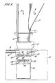
- Fig. 1 is a schematic cross-section through a filling apparatus with a container connected;
- Fig. 2 is a perspective view showing a single sliding gate valve; and
- Fig. 3 is a view similar to Fig. 1 with a container detached from the apparatus.
- The apparatus shown in Figs. 1 and 3 comprises at its uppermost end a powder delivery conduit 1 which has a Y-shape configuration. The ultra fine powder entrained in inert gas is fed downwardly through the left hand branch of the conduit 1 in a direction of arrow 2 and reverses its direction to flow up the right hand branch of the conduit 1 in the direction of arrow 3 and impinges on a filter cloth or bag (not shown) where the powder is compacted. Periodically, a gas pulse and/or vibration is applied to the cloth or bag to dislodge agglomerated particles of the powder which fall downwardly against the flow up the right hand branch of the conduit 1 into a collection chamber 4. Agglomerated powder is required to settle under the action of gravity. These agglomerates can be re-fragmented using weak mechanical forces (such as sonication). The lower end of the collection chamber 4 is sealed by a sealed disc valve assembly 5 of conventional construction. The temperature in the collection chamber 4 is monitored using a thermocouple and the disc valve assembly will only operate when the temperature drops to a defined level below the autoignition temperature of the collected material.
- Beneath the disc valve assembly 5 is a loading chamber 6 which is filled with low but above atmospheric pressure inert gas.
- An
intermediate chamber 7 is connected and sealed directly below the disc valve assembly 5 within the loading chamber 6. A high pressure inert gas supply line 8 leads to theintermediate chamber 7, while a purge line 9 leads from theintermediate chamber 7. Both lines are provided with control valves (not shown) to control the flow therethrough. Below the intermediate chamber is a first motorised pneumatic slidegate valve assembly 10 which is arranged to selectively seal the lower end of the intermediate chamber. This assembly comprises a pair of concentric O-rings 11 which surround the lowermost end of theintermediate chamber 7. Ahousing 12 depends beneath theintermediate chamber 7. Thehousing 12 is spaced from the lowermost surface of theintermediate chamber 7, and supports a pair oframps 14 as best shown in Fig. 2. Asliding gate member 15 is provided with a pair ofcomplementary ramp surfaces 16 which cooperate with theramps 14. The valve is shown in an open configuration in Fig. 1, in which thegate member 15 is retracted from thehousing 12, thereby leaving the bottom of theintermediate chamber 7 open. The gate member is shown closed in Fig. 3, in which thegate member 15 has been slid fully into thehousing 12. During the latter part of its travel, theramps 14 engage with theramp surfaces 16, so that further movement of thegate member 15 into thehousing 12 forces the gate member up against the O-rings 11, thereby sealing the bottom of theintermediate chamber 7. - As shown in Figs. 1 and 3, a
container 19 to be fitted to the delivery apparatus has a slide gate valve assembly 20 fitted to its uppermost surface. This slide gate valve assembly 20 has an identical configuration to the slidegate valve assembly 10, but is shown in an inverted configuration. A full description of this assembly 20 will therefore not be included here. However, the reference numerals used in Figs. 1 and 3 relate to those used for the slidegate valve assembly 10, except that each numeral begins with a 2 instead of a 1. Thus, the slide gate valve assembly has O-rings 21, ahousing 22,ramps 24, agate member 25 andramp surfaces 26. - The equipment is earth bonded to allow for the dissipation of static charge.
- The operation of the apparatus will now be described.
- Before use, the collection chamber 4, and the
intermediate chamber 7 are purged with inert gas. This gas is supplied to the equipment using remote solenoid valve control. Pressure acting known return valves are also provided to over-pressurising equipment during this purging operation. - The oxygen content within the equipment is continually monitored using a solid state zirconia cell device which is fitted with a pump to draw samples from both the collection chamber 4 and the loading chamber 6.
- A
container 19 is introduced into the loading chamber 6. Thecontainer 19 is brought into position beneath theintermediate chamber 7. The movement of the container into this position can be accomplished by a system of guide grooves along which the container is moved in order to bring it into the desired position. Initially,gate member 15 and.disc valve assembly 5 are closed. At this point the chamber 6 is purged with inert gas. The inert gas is supplied to the chamber 6 using remote solenoid valve control and pressure acting known return valves to avoid over-pressurising the chamber. Although thecontainer 19 is against thehousing 12, it is not sealed against it. Therefore, when the chamber 6 is purged, thevessel 19 is also purged as the purge gas is heavier than the atmospheric air within the vessel and therefore displaces the atmospheric air. The gap between thevessel 19 and thehousing 12 is sufficient to allow gas flow, but is small enough to prevent material escaping into the chamber 6. Thegate member 15 is opened followed by the disc valve assembly 5. There is now a complete path all the way down from theintermediate chamber 7 into thecontainer 19. - Then, as described above, the powder drops down through the entire assembly and into the
container 19. The gas purge through lines 8 and 9 is pulsed intermittently at this time to encourage the flow of material into thecontainer 19. Once thecontainer 19 is filled to the desired level, the disc valve assembly 5, then thegate member 15 are closed. This isolates theintermediate chamber 7 from the collection chamber 4, although both chambers have the same gaseous environment.Gate member 25 is then closed. With the slide gate valve assemblies closed, thecontainer 19 together with thegate member 25 can be released from its engagement with the slidegate valve assembly 10, and can be replaced by an empty container. The slide gate valve assembly 20 may be latched closed and/or spring loaded to ensure that the seal is maintained during further handling of the container. The chamber 6 is now opened to atmosphere and the container with thegate member 25 as its lid is removed. A new container is then placed into the chamber 6 with its lid open, and the above described process is repeated as often as necessary.
Claims (9)
- A method for packaging ultra fine powders into containers (19) in a controlled environment in a sealed apparatus in which the internal environment does not react with the powder and which comprises a powder delivery chamber to which a supply of the powder is supplied from the reaction production apparatus, the powder delivery chamber having a port for receiving a container, the port being selectively closable by a first valve (10) which seals the port, wherein each container is closable by a second valve (20) which seals the container; the method comprising the steps of closing the first valve to seal the port; attaching a container to the port; opening the first valve; with the second valve also open, introducing powder into the container; closing the first and second valves to seal the port and the container; and disconnecting the container from the port; characterised in that the lowermost part of the powder delivery chamber is housed within a loading chamber (6), and the method further comprises loading a container into the loading chamber, and purging the loading chamber and hence the container.
- A method according to claim 1, wherein at least one of the first (10) and second (20) valves is a sliding gate type valve, in which a gate member (15, 25) is slidable between an open configuration in which it does not obstruct the port or the entrance to the container, and a closed configuration in which it seals against the port or the entrance to the container (19).
- A method according to claim 2, wherein the gate member (15, 25) is provided with at least one ramp surface (16, 26) which cooperates with a complementary ramp (14, 24) in a valve housing, whereby sliding of the gate member with respect to the housing forces the ramp surface to ride up the ramp hence forcing the gate member into sealing engagement with the port or container.
- A method according to claim 3, wherein the port and/or container (19) is/are surrounded by at least one O-ring (11, 21) against which the gate member (15, 25) is sealed.
- A method according to any one of the preceding claims, wherein a third valve (5) is provided which is arranged to selectively isolate the part of the powder delivery chamber having the port from the remainder of the powder delivery chamber, thereby defining an intermediate chamber (7) between the first and third valves, a supply (8) of non-reactive gas is provided to the intermediate chamber, and a purge line (9) leads from the intermediate chamber, the method further comprising purging the intermediate chamber with non-reactive gas with the first (10) and third valves closed until the amount of reactive gas in the intermediate chamber reaches an acceptably low level.
- A combination of an apparatus for packaging ultra fine powders into containers, and at least one container (19), the apparatus comprising a sealed unit arranged to contain a non-reactive environment, a powder delivery chamber arranged to receive a supply of powder, the powder delivery chamber having a port for receiving a container, the port being selectively closable by a first valve (10) which seals the port and opening into a loading chamber (6) for receiving the container; the container being closable by a second valve (20) which seals the container, and the container having a surface which is arranged to engage with the port; characterised in that a third valve (5) is provided which is arranged to selectively isolate the part of the powder delivery chamber having the port from the remainder of the powder delivery chamber, thereby defining an intermediate chamber (7) between the first and third valves, a supply of non-reactive gas (8) is provided to the intermediate chamber, and a purge line (9) leads from the intermediate chamber forming a purge gas circuit to allow the leading chamber and the container therein to be purged.
- A combination according to claim 6, wherein at least one of the first and second valves is a sliding gate type, in which a gate member is slidable between an open configuration in which it does not obstruct the port or the entrance to the container, and a closed configuration in which it seals against the port or the entrance to the container.
- A combination according to claim 7, wherein the gate member is provided with at least one ramp surface which cooperates with a complementary ramp in a valve housing, whereby sliding of the gate member with respect to the housing forces the ramp surface to ride up the ramp hence forcing the plate into sealing engagement with the port or container.
- A combination according to claim 7 or claim 8, wherein the port and/or container is/are surrounded by at least by one O-ring against which the gate member is sealed.
Applications Claiming Priority (3)
| Application Number | Priority Date | Filing Date | Title |
|---|---|---|---|
| GBGB0004845.4A GB0004845D0 (en) | 2000-02-29 | 2000-02-29 | A method and apparatus for packaging ultra fine powders into containers |
| GB0004845 | 2000-02-29 | ||
| PCT/GB2001/000861 WO2001064521A1 (en) | 2000-02-29 | 2001-02-28 | A method and apparatus for packaging ultra fine powders into containers |
Publications (2)
| Publication Number | Publication Date |
|---|---|
| EP1259427A1 EP1259427A1 (en) | 2002-11-27 |
| EP1259427B1 true EP1259427B1 (en) | 2007-01-17 |
Family
ID=9886673
Family Applications (1)
| Application Number | Title | Priority Date | Filing Date |
|---|---|---|---|
| EP01907936A Expired - Lifetime EP1259427B1 (en) | 2000-02-29 | 2001-02-28 | A method and apparatus for packaging ultra fine powders into containers |
Country Status (11)
| Country | Link |
|---|---|
| US (1) | US6796107B2 (en) |
| EP (1) | EP1259427B1 (en) |
| JP (1) | JP2003525180A (en) |
| KR (1) | KR20030031887A (en) |
| CN (1) | CN1167581C (en) |
| AU (1) | AU3580201A (en) |
| CA (1) | CA2401538C (en) |
| DE (1) | DE60126064T2 (en) |
| GB (1) | GB0004845D0 (en) |
| RU (1) | RU2268848C2 (en) |
| WO (1) | WO2001064521A1 (en) |
Families Citing this family (9)
| Publication number | Priority date | Publication date | Assignee | Title |
|---|---|---|---|---|
| EP1963745A1 (en) * | 2005-12-22 | 2008-09-03 | International Environmental Solutions Corporation | Pyrolytic waste treatment system having dual knife gate valves |
| WO2008122529A1 (en) * | 2007-04-10 | 2008-10-16 | Mettler-Toledo Ag | Container unit for storing and protecting laboratory substances |
| FR2927062B1 (en) * | 2008-02-04 | 2011-07-01 | Arkema France | METHOD FOR SECURELY FILLING CARBON NANOTUBES, FILLING SYSTEM AND INDUSTRIAL PLANT USING THE METHOD |
| US20140352269A1 (en) * | 2011-12-15 | 2014-12-04 | Hatch Ltd. | Dust wash system with purge gas |
| BR112015008878A2 (en) * | 2012-12-04 | 2017-07-04 | Nestec Sa | apparatus and method for transferring and pressurizing dust |
| CN103101640B (en) * | 2013-02-25 | 2014-06-18 | 辽宁恒德磁业有限公司 | Ultrafine powder tinning structure |
| CN106276306B (en) * | 2016-08-28 | 2018-09-04 | 吴江市建设工程(集团)有限公司 | A kind of dry powder and mortar isolation-proof device |
| WO2018089482A1 (en) * | 2016-11-08 | 2018-05-17 | O.I. Corporation | Smart slide |
| PL3401244T3 (en) * | 2017-05-12 | 2023-03-13 | Primetals Technologies Austria GmbH | Conveyance of an item to be conveyed |
Family Cites Families (59)
| Publication number | Priority date | Publication date | Assignee | Title |
|---|---|---|---|---|
| US2284551A (en) | 1940-08-03 | 1942-05-26 | Peter P Alexander | Packing of powdered metals |
| US2694515A (en) * | 1952-03-26 | 1954-11-16 | United States Steel Corp | Funnel device for filling containers |
| BE557511A (en) * | 1956-05-14 | |||
| BE639079A (en) | 1962-10-26 | |||
| DE1220058B (en) | 1965-06-28 | 1966-06-30 | Kernforschung Gmbh Ges Fuer | Method and device for the heat treatment of powdery substances, in particular for melting the cores of high-melting substances, by means of a high-temperature plasma |
| GB1339054A (en) | 1971-05-13 | 1973-11-28 | Vos N I Gornorudny I Vostnigri | Apparatus for and a method of comminuting materials |
| JPS5546603B2 (en) | 1973-10-05 | 1980-11-25 | ||
| GB1493394A (en) | 1974-06-07 | 1977-11-30 | Nat Res Dev | Plasma heater assembly |
| US4112288A (en) | 1975-04-17 | 1978-09-05 | General Atomic Company | Orifice tip |
| US4194107A (en) | 1977-06-02 | 1980-03-18 | Klasson George A | Welding tip |
| DE2755213C2 (en) | 1977-12-10 | 1982-05-06 | Fa. Dr. Eugen Dürrwächter DODUCO, 7530 Pforzheim | Non-consumable electrode and method of making it |
| US4341941A (en) | 1979-03-01 | 1982-07-27 | Rikagaku Kenkyusho | Method of operating a plasma generating apparatus |
| US4238427A (en) | 1979-04-05 | 1980-12-09 | Chisholm Douglas S | Atomization of molten metals |
| US4299338A (en) * | 1979-09-27 | 1981-11-10 | Wyman-Gordon Company | Valve system |
| US4861961A (en) | 1981-03-04 | 1989-08-29 | Huys John H | Welding electrode |
| US4374075A (en) * | 1981-06-17 | 1983-02-15 | Crucible Inc. | Method for the plasma-arc production of metal powder |
| JPS5831825A (en) | 1981-08-14 | 1983-02-24 | Otsuka Tekko Kk | Equipment for filling pulverized coal into transport containers |
| US4610718A (en) * | 1984-04-27 | 1986-09-09 | Hitachi, Ltd. | Method for manufacturing ultra-fine particles |
| JPH062882B2 (en) | 1985-06-20 | 1994-01-12 | 大同特殊鋼株式会社 | Particle production equipment |
| DE3642375A1 (en) | 1986-12-11 | 1988-06-23 | Castolin Sa | METHOD FOR APPLYING AN INTERNAL COATING INTO TUBES OD. DGL. CAVITY NARROW CROSS SECTION AND PLASMA SPLASH BURNER DAFUER |
| JPS63147182A (en) | 1986-12-10 | 1988-06-20 | Tokai Rubber Ind Ltd | Manufacture of cleaning blade |
| US4856681A (en) * | 1988-08-29 | 1989-08-15 | Murray Charles T | Dispenser for granular and powdered dry materials |
| JP2659807B2 (en) * | 1989-01-26 | 1997-09-30 | 万鎔工業株式会社 | Direct smelting method |
| US5062936A (en) * | 1989-07-12 | 1991-11-05 | Thermo Electron Technologies Corporation | Method and apparatus for manufacturing ultrafine particles |
| JP2565575B2 (en) * | 1989-12-08 | 1996-12-18 | 三田工業株式会社 | Toner cartridge |
| JP3000610B2 (en) | 1990-03-14 | 2000-01-17 | 大同特殊鋼株式会社 | Method for producing hard particle dispersed alloy powder and hard particle dispersed alloy powder |
| DE4105407A1 (en) | 1991-02-21 | 1992-08-27 | Plasma Technik Ag | PLASMA SPRAYER FOR SPRAYING SOLID, POWDER-SHAPED OR GAS-SHAPED MATERIAL |
| FR2673990B1 (en) * | 1991-03-14 | 1993-07-16 | Sne Calhene | VALVE FORMING DEVICE FOR THE SEALED CONNECTION OF TWO CONTAINERS AND CONTAINER PROVIDED TO BE COUPLED TO SUCH A DEVICE. |
| GB9108891D0 (en) | 1991-04-25 | 1991-06-12 | Tetronics Research & Dev Co Li | Silica production |
| NO174180C (en) | 1991-12-12 | 1994-03-23 | Kvaerner Eng | Burner insertion tubes for chemical processes |
| JPH0680410A (en) | 1992-08-31 | 1994-03-22 | Sumitomo Heavy Ind Ltd | Carbon soot production equipment |
| DE9212623U1 (en) * | 1992-09-18 | 1993-08-05 | Alfred Bolz Gmbh & Co Kg, 88239 Wangen | Safety filling and emptying valve for liquid, pasty and powdery media |
| GB9224745D0 (en) | 1992-11-26 | 1993-01-13 | Atomic Energy Authority Uk | Microwave plasma generator |
| GB9300091D0 (en) * | 1993-01-05 | 1993-03-03 | Total Process Containment Ltd | Process material transfer |
| DE4307346A1 (en) | 1993-03-09 | 1994-09-15 | Loedige Maschbau Gmbh Geb | Safety locking device for container openings |
| JPH06272047A (en) | 1993-03-16 | 1994-09-27 | Mitsubishi Cable Ind Ltd | Method for producing coated powder and device therefor |
| FR2703340B1 (en) * | 1993-04-01 | 1995-06-30 | Elveco Msj Sa | INSTALLATION AND METHOD FOR TRANSFERRING GRAVITY FLOWING PRODUCTS. |
| JPH06299209A (en) | 1993-04-14 | 1994-10-25 | Sansha Electric Mfg Co Ltd | Formation of powder granule of magnetic material |
| US5460701A (en) * | 1993-07-27 | 1995-10-24 | Nanophase Technologies Corporation | Method of making nanostructured materials |
| US5408066A (en) | 1993-10-13 | 1995-04-18 | Trapani; Richard D. | Powder injection apparatus for a plasma spray gun |
| JPH07243756A (en) | 1994-03-09 | 1995-09-19 | Sanyo Electric Co Ltd | Storage container structure |
| JP2549273B2 (en) * | 1994-04-28 | 1996-10-30 | 鎌長製衡株式会社 | Deaeration device for powder filling machine |
| FR2720372B1 (en) * | 1994-05-31 | 1996-08-14 | Sne Calhene | Interface device for the transfer of fluid products between two containers. |
| US5420391B1 (en) | 1994-06-20 | 1998-06-09 | Metcon Services Ltd | Plasma torch with axial injection of feedstock |
| US5526358A (en) | 1994-08-19 | 1996-06-11 | Peerlogic, Inc. | Node management in scalable distributed computing enviroment |
| US5593740A (en) | 1995-01-17 | 1997-01-14 | Synmatix Corporation | Method and apparatus for making carbon-encapsulated ultrafine metal particles |
| US6063243A (en) | 1995-02-14 | 2000-05-16 | The Regents Of The Univeristy Of California | Method for making nanotubes and nanoparticles |
| JPH08243756A (en) | 1995-03-03 | 1996-09-24 | Mitsubishi Materials Corp | Welding torch for plasma overlay and overlay welding method |
| US5555995A (en) * | 1995-03-31 | 1996-09-17 | Galer; Herbert W. | Square container for hazardous powdered materials |
| US5935461A (en) * | 1996-07-25 | 1999-08-10 | Utron Inc. | Pulsed high energy synthesis of fine metal powders |
| JP3409974B2 (en) | 1996-08-23 | 2003-05-26 | 同和鉱業株式会社 | Powder storage / transportation tool that dislikes contact with air |
| JPH10216959A (en) | 1997-01-31 | 1998-08-18 | Inoue Seisakusho:Kk | Electrode for resistance welding |
| JP3041413B2 (en) | 1997-03-10 | 2000-05-15 | 工業技術院長 | Production method of layered aluminum particles and its application |
| GB9707641D0 (en) * | 1997-04-15 | 1997-06-04 | Matcon R & D Ltd | Apparatus and system for handling material |
| JPH11147511A (en) * | 1997-11-17 | 1999-06-02 | Sumitomo Metal Mining Co Ltd | Material filling equipment |
| DE19755350A1 (en) | 1997-12-12 | 1999-06-17 | Henkel Kgaa | Process for pickling and passivating stainless steel |
| DE19817735C1 (en) * | 1998-04-21 | 1999-11-11 | Fehland Engineering Gmbh | Beverage filling device |
| FR2792607B1 (en) * | 1999-04-22 | 2001-07-06 | Cogema | METHOD FOR FILLING, WITH A POWDERY PRODUCT, A CONTAINER CAPABLE OF A LID AND DEVICE FOR TRANSFERRING THE SAME |
| US6311745B1 (en) * | 2000-06-05 | 2001-11-06 | Xerox Corporation | Systems and methods for dispensing powders |
-
2000
- 2000-02-29 GB GBGB0004845.4A patent/GB0004845D0/en not_active Ceased
-
2001
- 2001-02-28 CA CA002401538A patent/CA2401538C/en not_active Expired - Fee Related
- 2001-02-28 US US10/220,075 patent/US6796107B2/en not_active Expired - Fee Related
- 2001-02-28 RU RU2002125856/13A patent/RU2268848C2/en not_active IP Right Cessation
- 2001-02-28 WO PCT/GB2001/000861 patent/WO2001064521A1/en not_active Ceased
- 2001-02-28 JP JP2001563383A patent/JP2003525180A/en not_active Ceased
- 2001-02-28 CN CNB018057578A patent/CN1167581C/en not_active Expired - Fee Related
- 2001-02-28 AU AU35802/01A patent/AU3580201A/en not_active Abandoned
- 2001-02-28 DE DE60126064T patent/DE60126064T2/en not_active Expired - Lifetime
- 2001-02-28 EP EP01907936A patent/EP1259427B1/en not_active Expired - Lifetime
- 2001-02-28 KR KR1020027011066A patent/KR20030031887A/en not_active Ceased
Also Published As
| Publication number | Publication date |
|---|---|
| RU2268848C2 (en) | 2006-01-27 |
| CN1167581C (en) | 2004-09-22 |
| JP2003525180A (en) | 2003-08-26 |
| WO2001064521A1 (en) | 2001-09-07 |
| CA2401538A1 (en) | 2001-09-07 |
| CA2401538C (en) | 2009-09-08 |
| CN1406191A (en) | 2003-03-26 |
| DE60126064T2 (en) | 2007-11-08 |
| US20030101690A1 (en) | 2003-06-05 |
| DE60126064D1 (en) | 2007-03-08 |
| EP1259427A1 (en) | 2002-11-27 |
| GB0004845D0 (en) | 2000-04-19 |
| RU2002125856A (en) | 2004-03-10 |
| AU3580201A (en) | 2001-09-12 |
| US6796107B2 (en) | 2004-09-28 |
| KR20030031887A (en) | 2003-04-23 |
Similar Documents
| Publication | Publication Date | Title |
|---|---|---|
| US6796107B2 (en) | Method and apparatus for packaging ultra fine powders into containers | |
| EP0556193B1 (en) | Method and apparatus for transferring articles between two controlled environments | |
| CN101503117B (en) | Method for safely filling carbon nanotubes and filling system and plant using the method | |
| US7547204B2 (en) | Nano-precision sintering system | |
| US5697750A (en) | Controlled environment enclosure and mechanical interface | |
| US3996725A (en) | Apparatus for filling and hermetically sealing thermoplastic containers under vacuum | |
| JP4873581B2 (en) | Apparatus and method for loading or discharging contents in a container containing flammable and erosive gas | |
| EP0570967B1 (en) | Vacuum container | |
| US2284551A (en) | Packing of powdered metals | |
| US4650640A (en) | Method and apparatus for loading fuel rods into a container | |
| CN101277760A (en) | Large-scale mechanical refining and screening of alloys | |
| EP2125522A1 (en) | Method and apparatus for compacting flowable solids | |
| CN112317745A (en) | Automatic additive manufacturing powder storage device and storage method | |
| JP2547228B2 (en) | Powder filling device | |
| WO2005043128A1 (en) | Sampling particulate material | |
| US20090110517A1 (en) | Catalyst Flow Control Device for Transfer of Solids Between Two Vessels | |
| AU773851B2 (en) | Method of charging a pressurized container with granular solids | |
| JPH0718561Y2 (en) | Powder filling device | |
| JPH01124501A (en) | Powder packing apparatus | |
| US20250214728A1 (en) | System and method for packaging and storing dry ice | |
| DE3071533D1 (en) | Aseptic container filler apparatus | |
| US20100014946A1 (en) | Catalyst flow control device for transfer of solids between two vessels | |
| EP0596536A1 (en) | Transport system and method of using same | |
| JPH01111601A (en) | Powder packing apparatus | |
| CA1265261A (en) | Container for receiving irradiated material |
Legal Events
| Date | Code | Title | Description |
|---|---|---|---|
| PUAI | Public reference made under article 153(3) epc to a published international application that has entered the european phase |
Free format text: ORIGINAL CODE: 0009012 |
|
| AK | Designated contracting states |
Kind code of ref document: A1 Designated state(s): AT BE CH CY DE DK ES FI FR GB GR IE IT LI LU MC NL PT SE TR |
|
| AX | Request for extension of the european patent |
Free format text: AL;LT;LV;MK;RO;SI |
|
| 17P | Request for examination filed |
Effective date: 20020820 |
|
| 17Q | First examination report despatched |
Effective date: 20031030 |
|
| GRAP | Despatch of communication of intention to grant a patent |
Free format text: ORIGINAL CODE: EPIDOSNIGR1 |
|
| RIN1 | Information on inventor provided before grant (corrected) |
Inventor name: DEEGAN, DAVID EDWARD Inventor name: CHAPMAN, CHRISTOPHER DAVID Inventor name: JOHNSON, TIMOTHY PAUL |
|
| RAP1 | Party data changed (applicant data changed or rights of an application transferred) |
Owner name: TETRONICS LIMITED |
|
| GRAF | Information related to payment of grant fee modified |
Free format text: ORIGINAL CODE: EPIDOSCIGR3 |
|
| GRAS | Grant fee paid |
Free format text: ORIGINAL CODE: EPIDOSNIGR3 |
|
| GRAA | (expected) grant |
Free format text: ORIGINAL CODE: 0009210 |
|
| AK | Designated contracting states |
Kind code of ref document: B1 Designated state(s): AT BE CH CY DE DK ES FI FR GB GR IE IT LI LU MC NL PT SE TR |
|
| PG25 | Lapsed in a contracting state [announced via postgrant information from national office to epo] |
Ref country code: LI Free format text: LAPSE BECAUSE OF FAILURE TO SUBMIT A TRANSLATION OF THE DESCRIPTION OR TO PAY THE FEE WITHIN THE PRESCRIBED TIME-LIMIT Effective date: 20070117 Ref country code: FI Free format text: LAPSE BECAUSE OF FAILURE TO SUBMIT A TRANSLATION OF THE DESCRIPTION OR TO PAY THE FEE WITHIN THE PRESCRIBED TIME-LIMIT Effective date: 20070117 Ref country code: CH Free format text: LAPSE BECAUSE OF FAILURE TO SUBMIT A TRANSLATION OF THE DESCRIPTION OR TO PAY THE FEE WITHIN THE PRESCRIBED TIME-LIMIT Effective date: 20070117 Ref country code: DK Free format text: LAPSE BECAUSE OF FAILURE TO SUBMIT A TRANSLATION OF THE DESCRIPTION OR TO PAY THE FEE WITHIN THE PRESCRIBED TIME-LIMIT Effective date: 20070117 Ref country code: NL Free format text: LAPSE BECAUSE OF FAILURE TO SUBMIT A TRANSLATION OF THE DESCRIPTION OR TO PAY THE FEE WITHIN THE PRESCRIBED TIME-LIMIT Effective date: 20070117 Ref country code: AT Free format text: LAPSE BECAUSE OF FAILURE TO SUBMIT A TRANSLATION OF THE DESCRIPTION OR TO PAY THE FEE WITHIN THE PRESCRIBED TIME-LIMIT Effective date: 20070117 |
|
| REG | Reference to a national code |
Ref country code: GB Ref legal event code: FG4D |
|
| REG | Reference to a national code |
Ref country code: CH Ref legal event code: EP |
|
| PG25 | Lapsed in a contracting state [announced via postgrant information from national office to epo] |
Ref country code: MC Free format text: LAPSE BECAUSE OF NON-PAYMENT OF DUE FEES Effective date: 20070228 |
|
| REG | Reference to a national code |
Ref country code: IE Ref legal event code: FG4D |
|
| REF | Corresponds to: |
Ref document number: 60126064 Country of ref document: DE Date of ref document: 20070308 Kind code of ref document: P |
|
| PG25 | Lapsed in a contracting state [announced via postgrant information from national office to epo] |
Ref country code: SE Free format text: LAPSE BECAUSE OF FAILURE TO SUBMIT A TRANSLATION OF THE DESCRIPTION OR TO PAY THE FEE WITHIN THE PRESCRIBED TIME-LIMIT Effective date: 20070417 |
|
| PG25 | Lapsed in a contracting state [announced via postgrant information from national office to epo] |
Ref country code: ES Free format text: LAPSE BECAUSE OF FAILURE TO SUBMIT A TRANSLATION OF THE DESCRIPTION OR TO PAY THE FEE WITHIN THE PRESCRIBED TIME-LIMIT Effective date: 20070428 |
|
| PG25 | Lapsed in a contracting state [announced via postgrant information from national office to epo] |
Ref country code: PT Free format text: LAPSE BECAUSE OF FAILURE TO SUBMIT A TRANSLATION OF THE DESCRIPTION OR TO PAY THE FEE WITHIN THE PRESCRIBED TIME-LIMIT Effective date: 20070618 |
|
| NLV1 | Nl: lapsed or annulled due to failure to fulfill the requirements of art. 29p and 29m of the patents act | ||
| REG | Reference to a national code |
Ref country code: CH Ref legal event code: PL |
|
| REG | Reference to a national code |
Ref country code: GB Ref legal event code: 732E |
|
| PLBE | No opposition filed within time limit |
Free format text: ORIGINAL CODE: 0009261 |
|
| STAA | Information on the status of an ep patent application or granted ep patent |
Free format text: STATUS: NO OPPOSITION FILED WITHIN TIME LIMIT |
|
| 26N | No opposition filed |
Effective date: 20071018 |
|
| PG25 | Lapsed in a contracting state [announced via postgrant information from national office to epo] |
Ref country code: BE Free format text: LAPSE BECAUSE OF FAILURE TO SUBMIT A TRANSLATION OF THE DESCRIPTION OR TO PAY THE FEE WITHIN THE PRESCRIBED TIME-LIMIT Effective date: 20070117 |
|
| PG25 | Lapsed in a contracting state [announced via postgrant information from national office to epo] |
Ref country code: IE Free format text: LAPSE BECAUSE OF NON-PAYMENT OF DUE FEES Effective date: 20070228 |
|
| PG25 | Lapsed in a contracting state [announced via postgrant information from national office to epo] |
Ref country code: GR Free format text: LAPSE BECAUSE OF FAILURE TO SUBMIT A TRANSLATION OF THE DESCRIPTION OR TO PAY THE FEE WITHIN THE PRESCRIBED TIME-LIMIT Effective date: 20070418 Ref country code: IT Free format text: LAPSE BECAUSE OF FAILURE TO SUBMIT A TRANSLATION OF THE DESCRIPTION OR TO PAY THE FEE WITHIN THE PRESCRIBED TIME-LIMIT Effective date: 20070117 Ref country code: FR Free format text: LAPSE BECAUSE OF FAILURE TO SUBMIT A TRANSLATION OF THE DESCRIPTION OR TO PAY THE FEE WITHIN THE PRESCRIBED TIME-LIMIT Effective date: 20070907 |
|
| PG25 | Lapsed in a contracting state [announced via postgrant information from national office to epo] |
Ref country code: FR Free format text: LAPSE BECAUSE OF FAILURE TO SUBMIT A TRANSLATION OF THE DESCRIPTION OR TO PAY THE FEE WITHIN THE PRESCRIBED TIME-LIMIT Effective date: 20070117 |
|
| PG25 | Lapsed in a contracting state [announced via postgrant information from national office to epo] |
Ref country code: CY Free format text: LAPSE BECAUSE OF FAILURE TO SUBMIT A TRANSLATION OF THE DESCRIPTION OR TO PAY THE FEE WITHIN THE PRESCRIBED TIME-LIMIT Effective date: 20070117 |
|
| PG25 | Lapsed in a contracting state [announced via postgrant information from national office to epo] |
Ref country code: LU Free format text: LAPSE BECAUSE OF NON-PAYMENT OF DUE FEES Effective date: 20070228 |
|
| PG25 | Lapsed in a contracting state [announced via postgrant information from national office to epo] |
Ref country code: TR Free format text: LAPSE BECAUSE OF FAILURE TO SUBMIT A TRANSLATION OF THE DESCRIPTION OR TO PAY THE FEE WITHIN THE PRESCRIBED TIME-LIMIT Effective date: 20070117 |
|
| PGFP | Annual fee paid to national office [announced via postgrant information from national office to epo] |
Ref country code: DE Payment date: 20110419 Year of fee payment: 11 |
|
| REG | Reference to a national code |
Ref country code: DE Ref legal event code: R119 Ref document number: 60126064 Country of ref document: DE Effective date: 20120901 |
|
| PG25 | Lapsed in a contracting state [announced via postgrant information from national office to epo] |
Ref country code: DE Free format text: LAPSE BECAUSE OF NON-PAYMENT OF DUE FEES Effective date: 20120901 |
|
| PGFP | Annual fee paid to national office [announced via postgrant information from national office to epo] |
Ref country code: GB Payment date: 20170222 Year of fee payment: 17 |
|
| GBPC | Gb: european patent ceased through non-payment of renewal fee |
Effective date: 20180228 |
|
| PG25 | Lapsed in a contracting state [announced via postgrant information from national office to epo] |
Ref country code: GB Free format text: LAPSE BECAUSE OF NON-PAYMENT OF DUE FEES Effective date: 20180228 |