EP1259363B1 - A body formed of set, initially pasty material and including an electrically conducting path and a method of making such a body - Google Patents
A body formed of set, initially pasty material and including an electrically conducting path and a method of making such a body Download PDFInfo
- Publication number
- EP1259363B1 EP1259363B1 EP00987938A EP00987938A EP1259363B1 EP 1259363 B1 EP1259363 B1 EP 1259363B1 EP 00987938 A EP00987938 A EP 00987938A EP 00987938 A EP00987938 A EP 00987938A EP 1259363 B1 EP1259363 B1 EP 1259363B1
- Authority
- EP
- European Patent Office
- Prior art keywords
- pasty material
- electrically conducting
- layer
- fibres
- stratifying
- Prior art date
- Legal status (The legal status is an assumption and is not a legal conclusion. Google has not performed a legal analysis and makes no representation as to the accuracy of the status listed.)
- Expired - Lifetime
Links
Images


Classifications
-
- B—PERFORMING OPERATIONS; TRANSPORTING
- B28—WORKING CEMENT, CLAY, OR STONE
- B28B—SHAPING CLAY OR OTHER CERAMIC COMPOSITIONS; SHAPING SLAG; SHAPING MIXTURES CONTAINING CEMENTITIOUS MATERIAL, e.g. PLASTER
- B28B1/00—Producing shaped prefabricated articles from the material
- B28B1/52—Producing shaped prefabricated articles from the material specially adapted for producing articles from mixtures containing fibres, e.g. asbestos cement
- B28B1/523—Producing shaped prefabricated articles from the material specially adapted for producing articles from mixtures containing fibres, e.g. asbestos cement containing metal fibres
-
- B—PERFORMING OPERATIONS; TRANSPORTING
- B28—WORKING CEMENT, CLAY, OR STONE
- B28B—SHAPING CLAY OR OTHER CERAMIC COMPOSITIONS; SHAPING SLAG; SHAPING MIXTURES CONTAINING CEMENTITIOUS MATERIAL, e.g. PLASTER
- B28B1/00—Producing shaped prefabricated articles from the material
- B28B1/52—Producing shaped prefabricated articles from the material specially adapted for producing articles from mixtures containing fibres, e.g. asbestos cement
-
- B—PERFORMING OPERATIONS; TRANSPORTING
- B28—WORKING CEMENT, CLAY, OR STONE
- B28B—SHAPING CLAY OR OTHER CERAMIC COMPOSITIONS; SHAPING SLAG; SHAPING MIXTURES CONTAINING CEMENTITIOUS MATERIAL, e.g. PLASTER
- B28B1/00—Producing shaped prefabricated articles from the material
- B28B1/08—Producing shaped prefabricated articles from the material by vibrating or jolting
- B28B1/084—Producing shaped prefabricated articles from the material by vibrating or jolting the vibrating moulds or cores being moved horizontally for making strands of moulded articles
-
- C—CHEMISTRY; METALLURGY
- C04—CEMENTS; CONCRETE; ARTIFICIAL STONE; CERAMICS; REFRACTORIES
- C04B—LIME, MAGNESIA; SLAG; CEMENTS; COMPOSITIONS THEREOF, e.g. MORTARS, CONCRETE OR LIKE BUILDING MATERIALS; ARTIFICIAL STONE; CERAMICS; REFRACTORIES; TREATMENT OF NATURAL STONE
- C04B28/00—Compositions of mortars, concrete or artificial stone, containing inorganic binders or the reaction product of an inorganic and an organic binder, e.g. polycarboxylate cements
- C04B28/02—Compositions of mortars, concrete or artificial stone, containing inorganic binders or the reaction product of an inorganic and an organic binder, e.g. polycarboxylate cements containing hydraulic cements other than calcium sulfates
-
- E—FIXED CONSTRUCTIONS
- E01—CONSTRUCTION OF ROADS, RAILWAYS, OR BRIDGES
- E01C—CONSTRUCTION OF, OR SURFACES FOR, ROADS, SPORTS GROUNDS, OR THE LIKE; MACHINES OR AUXILIARY TOOLS FOR CONSTRUCTION OR REPAIR
- E01C11/00—Details of pavings
- E01C11/24—Methods or arrangements for preventing slipperiness or protecting against influences of the weather
- E01C11/26—Permanently installed heating or blowing devices ; Mounting thereof
- E01C11/265—Embedded electrical heating elements ; Mounting thereof
-
- E—FIXED CONSTRUCTIONS
- E01—CONSTRUCTION OF ROADS, RAILWAYS, OR BRIDGES
- E01C—CONSTRUCTION OF, OR SURFACES FOR, ROADS, SPORTS GROUNDS, OR THE LIKE; MACHINES OR AUXILIARY TOOLS FOR CONSTRUCTION OR REPAIR
- E01C19/00—Machines, tools or auxiliary devices for preparing or distributing paving materials, for working the placed materials, or for forming, consolidating, or finishing the paving
- E01C19/22—Machines, tools or auxiliary devices for preparing or distributing paving materials, for working the placed materials, or for forming, consolidating, or finishing the paving for consolidating or finishing laid-down unset materials
- E01C19/44—Hand-actuated tools other than rollers, tampers, or vibrators, specially adapted for imparting a required finish to freshly-laid paving courses
-
- E—FIXED CONSTRUCTIONS
- E04—BUILDING
- E04F—FINISHING WORK ON BUILDINGS, e.g. STAIRS, FLOORS
- E04F15/00—Flooring
- E04F15/12—Flooring or floor layers made of masses in situ, e.g. seamless magnesite floors, terrazzo gypsum floors
-
- E—FIXED CONSTRUCTIONS
- E04—BUILDING
- E04F—FINISHING WORK ON BUILDINGS, e.g. STAIRS, FLOORS
- E04F21/00—Implements for finishing work on buildings
- E04F21/20—Implements for finishing work on buildings for laying flooring
- E04F21/24—Implements for finishing work on buildings for laying flooring of masses made in situ, e.g. smoothing tools
- E04F21/241—Elongated smoothing blades or plates, e.g. screed apparatus
- E04F21/242—Elongated smoothing blades or plates, e.g. screed apparatus with vibrating means, e.g. vibrating screeds
-
- E—FIXED CONSTRUCTIONS
- E04—BUILDING
- E04F—FINISHING WORK ON BUILDINGS, e.g. STAIRS, FLOORS
- E04F21/00—Implements for finishing work on buildings
- E04F21/20—Implements for finishing work on buildings for laying flooring
- E04F21/24—Implements for finishing work on buildings for laying flooring of masses made in situ, e.g. smoothing tools
- E04F21/241—Elongated smoothing blades or plates, e.g. screed apparatus
- E04F21/244—Elongated smoothing blades or plates, e.g. screed apparatus with means to adjust the working angle of the leveling blade or plate
-
- C—CHEMISTRY; METALLURGY
- C04—CEMENTS; CONCRETE; ARTIFICIAL STONE; CERAMICS; REFRACTORIES
- C04B—LIME, MAGNESIA; SLAG; CEMENTS; COMPOSITIONS THEREOF, e.g. MORTARS, CONCRETE OR LIKE BUILDING MATERIALS; ARTIFICIAL STONE; CERAMICS; REFRACTORIES; TREATMENT OF NATURAL STONE
- C04B2111/00—Mortars, concrete or artificial stone or mixtures to prepare them, characterised by specific function, property or use
- C04B2111/90—Electrical properties
- C04B2111/94—Electrically conducting materials
-
- Y—GENERAL TAGGING OF NEW TECHNOLOGICAL DEVELOPMENTS; GENERAL TAGGING OF CROSS-SECTIONAL TECHNOLOGIES SPANNING OVER SEVERAL SECTIONS OF THE IPC; TECHNICAL SUBJECTS COVERED BY FORMER USPC CROSS-REFERENCE ART COLLECTIONS [XRACs] AND DIGESTS
- Y10—TECHNICAL SUBJECTS COVERED BY FORMER USPC
- Y10T—TECHNICAL SUBJECTS COVERED BY FORMER US CLASSIFICATION
- Y10T428/00—Stock material or miscellaneous articles
- Y10T428/12—All metal or with adjacent metals
- Y10T428/12014—All metal or with adjacent metals having metal particles
- Y10T428/12021—All metal or with adjacent metals having metal particles having composition or density gradient or differential porosity
-
- Y—GENERAL TAGGING OF NEW TECHNOLOGICAL DEVELOPMENTS; GENERAL TAGGING OF CROSS-SECTIONAL TECHNOLOGIES SPANNING OVER SEVERAL SECTIONS OF THE IPC; TECHNICAL SUBJECTS COVERED BY FORMER USPC CROSS-REFERENCE ART COLLECTIONS [XRACs] AND DIGESTS
- Y10—TECHNICAL SUBJECTS COVERED BY FORMER USPC
- Y10T—TECHNICAL SUBJECTS COVERED BY FORMER US CLASSIFICATION
- Y10T428/00—Stock material or miscellaneous articles
- Y10T428/12—All metal or with adjacent metals
- Y10T428/12465—All metal or with adjacent metals having magnetic properties, or preformed fiber orientation coordinate with shape
-
- Y—GENERAL TAGGING OF NEW TECHNOLOGICAL DEVELOPMENTS; GENERAL TAGGING OF CROSS-SECTIONAL TECHNOLOGIES SPANNING OVER SEVERAL SECTIONS OF THE IPC; TECHNICAL SUBJECTS COVERED BY FORMER USPC CROSS-REFERENCE ART COLLECTIONS [XRACs] AND DIGESTS
- Y10—TECHNICAL SUBJECTS COVERED BY FORMER USPC
- Y10T—TECHNICAL SUBJECTS COVERED BY FORMER US CLASSIFICATION
- Y10T428/00—Stock material or miscellaneous articles
- Y10T428/24—Structurally defined web or sheet [e.g., overall dimension, etc.]
- Y10T428/24132—Structurally defined web or sheet [e.g., overall dimension, etc.] including grain, strips, or filamentary elements in different layers or components parallel
-
- Y—GENERAL TAGGING OF NEW TECHNOLOGICAL DEVELOPMENTS; GENERAL TAGGING OF CROSS-SECTIONAL TECHNOLOGIES SPANNING OVER SEVERAL SECTIONS OF THE IPC; TECHNICAL SUBJECTS COVERED BY FORMER USPC CROSS-REFERENCE ART COLLECTIONS [XRACs] AND DIGESTS
- Y10—TECHNICAL SUBJECTS COVERED BY FORMER USPC
- Y10T—TECHNICAL SUBJECTS COVERED BY FORMER US CLASSIFICATION
- Y10T428/00—Stock material or miscellaneous articles
- Y10T428/24—Structurally defined web or sheet [e.g., overall dimension, etc.]
- Y10T428/24802—Discontinuous or differential coating, impregnation or bond [e.g., artwork, printing, retouched photograph, etc.]
- Y10T428/24893—Discontinuous or differential coating, impregnation or bond [e.g., artwork, printing, retouched photograph, etc.] including particulate material
- Y10T428/24909—Free metal or mineral containing
-
- Y—GENERAL TAGGING OF NEW TECHNOLOGICAL DEVELOPMENTS; GENERAL TAGGING OF CROSS-SECTIONAL TECHNOLOGIES SPANNING OVER SEVERAL SECTIONS OF THE IPC; TECHNICAL SUBJECTS COVERED BY FORMER USPC CROSS-REFERENCE ART COLLECTIONS [XRACs] AND DIGESTS
- Y10—TECHNICAL SUBJECTS COVERED BY FORMER USPC
- Y10T—TECHNICAL SUBJECTS COVERED BY FORMER US CLASSIFICATION
- Y10T428/00—Stock material or miscellaneous articles
- Y10T428/249921—Web or sheet containing structurally defined element or component
- Y10T428/249924—Noninterengaged fiber-containing paper-free web or sheet which is not of specified porosity
- Y10T428/249932—Fiber embedded in a layer derived from a water-settable material [e.g., cement, gypsum, etc.]
Definitions
- This invention relates a body formed of a set, initially pasty material and including an electrically conducting path. Moreover, the invention relates to a method of making such a body.
- a magnetic field is directed through the newly cast, wet concrete body in the casting form and displaced relative to the form from one end or side thereof to the other in order to apply a temporary aligning force to the individual fibres for aligning them in the direction of relative movement (US-A-4 062 913).
- the concrete body is vibrated during the relative movement of the magnetic field and the concrete body.
- conducting fibres which are randomly orientated or one-dimensionally aligned by the known technique are not suitable for such purposes, because they do not provide a suitable electrically conducting path through the concrete and because it is difficult to obtain a satisfactory connection of electrical terminal members to the fibres.
- the concrete itself is a poor conductor and the fibres are substantially evenly distributed throughout the concrete so that only few fibres contact each other. For that reason, the fibres do not provide a coherent and wide current path between the terminal members.
- An object of the invention is to provide an improved body of the kind indicated above.
- a further object is to provide a method of making such a body.
- body formed of a set, initially pasty material and including an electrically conducting path formed by a concentrated layer of electrically conducting magnetizable fibrous and/or granular elements, said layer being embedded in said material and extending through at least a portion of said body.
- the initially more or less randomly distributed magnetizable fibrous and/or granular elements in the pasty material which may be concrete, for example, are ultimately stratified to form a layer in which they are substantially more densely arranged than initially, a sufficiently large number of fibres or granular elements are sufficiently close or contact one another throughout the extent of the layer to provide between the terminal members a conducting path of adequate current carrying or shielding capability.
- the layer is positioned such that it extends generally parallel to a face of the body, which may be, for example a slab or some other plate-like body. If the body is to be used in an application in which it is desirable to pass an electric current through the electrically conducting path formed of or including the layer, e.g. to heat the body, the body preferably includes electrically conducting terminal members connected to the electrically conducting layer at spaced-apart positions along the layer.
- the layer of magnetizable elements is made up of or includes reinforcing fibres of metal, it suitably is positioned in the body where the demand for reinforcement is the greatest.
- the thinning out of the fibre reinforcement in other parts of the body resulting from the concentration of the fibres to a single or a few layers therefore need not entail any serious loss of the strength of the body.
- a method of providing an electrically conducting path in a body formed of a set, initially pasty material including the steps of forming a body of the pasty material in which electrically conducting magnetizable fibrous or granular elements are dispersed, applying a magnetic field to the body of pasty material to form from the said magnetizable elements an electrically conducting layer embedded in said body of pasty material and extending at least through a portion thereof, causing said body of pasty material containing said layer to set, and connecting electrically conducting terminal members to said electrically conducting layer at spaced-apart positions along the layer.
- Aggregate in the form of granular iron ore (magnetite) or other magnetizable granular material having some electrical conductivity may form the layer alone or, preferably, together with magnetizable metal fibres. In the latter case, the conducting granular material will reduce the resistivity of the portions of the initially pasty material separating the fibres.
- the stratification of the magnetizable fibrous and/or granular elements by magnetic means in accordance with the method of the invention may be carried out by the method and the device for stratifying and aligning magnetizable metal fibres which are described and claimed in International Application PCT/SE99/01150, published as W099/67072.
- the magnetic stratification and alignment of magnetizable fibres dispersed in a viscous or pasty body is carried out by means of a stratifying member having a nonmagnetic wall.
- a magnetic field is directed into the viscous body through a first portion of the nonmagnetic wall while the fibre-stratifying member is being moved relative to the body of pasty material with the nonmagnetic wall contacting the body and with a second portion of the nonmagnetic portion trailing the first portion. Accordingly, the fibres are temporarily subjected to the magnetic field as the first portion moves past them.
- the fibre-stratifying member may be partially or completely immersed in the pasty material as it is moved relative to the body with the first portion of the magnetic wall ahead of the second portion and thus trailed by the latter.
- the fibres in the vicinity of the first portion of the nonmagnetic wall are magnetically attracted towards the first portion. However, they are prevented from coming into contact with the magnetic device by the nonmagnetic wall, which forms a screen or barrier that separates the magnet device from the pasty material in which the fibres are dispersed.
- the fibre-stratifying member therefore attracts the fibres and tends to pull them along in the direction of its movement relative to the body of pasty material. Because of its viscosity or pasty character, the material of the body prevents the fibres from moving too rapidly towards the stratifying member and sticking to it. Thus, the fibre-stratifying member will move relative to the fibres and subject them to the magnetic force only temporarily. Since the magnetic force has a component in the direction of relative moment of the fibre-stratifying member and the pasty body, it not only will draw the fibres towards the fibre-stratifying member and thus stratify them to form a densified fibre layer within the body, but also tends to align the fibres in that direction as it moves past them.
- the pasty material containing the fibres is vibrated adjacent the fibre-stratifying member so that the stratifying and aligning movement of the fibres is facilitated.
- the terminal members may be connected to the conducting layer formed by the densified layer of fibres or other magnetizable conducting elements in any suitable manner, before or after the pasty material has set.
- the concrete or other pasty material it may be locally removed to expose the conducting layer in a narrow groove extending across the layer, whereupon a braided strip of copper wire or some other suitable form of "bus bar" conductor adapted for connection to an electric power source, is placed across the layer and secured to it by pouring molten tin over the strip and the exposed layer.
- Fig. 1 is a diagrammatic perspective view illustrating the basic principle of the invention as applied to a concrete slab having an electrically conducting path formed from a concentrated layer of magnetizable reinforcing fibres;
- Fig 1A is an enlarged perspective view of a corner of the slab shown in Fig. 1;
- Fig. 2 is an overview illustration showing successive steps in the production of a concrete pavement on the ground, one of the steps being the formation of a concentrated layer of reinforcing steel fibres in accordance with the invention
- Fig. 3 is a perspective view of a fibre-stratifying device used in the step shown in Fig. 2;
- Fig. 4 is a cross-sectional view of the section of the concrete pavement of Fig. 2 in which the fibre stratification is being carried out;
- Figs. 5-7 are diagrammatic views of three slabs of different heights cast on the ground and shown together with fibre-stratifying devices;
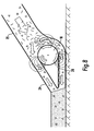
- Fig. 8 is a cross-sectional view showing a modification of the device of Fig. 7;
- Fig. 9 is a cross-sectional view showing a modification of the fibre-stratifying device of Fig. 4.
- Figs. 1 and 1A show a rectangular flat concrete body 5, a slab, which is reinforced by means of a multiplicity of magnetizable metal fibres embedded in the concrete and included in a concentrated layer 6 of densely packed fibres F.
- This layer extends from one end 7 of the concrete body to the other end 8 and is positioned between and parallel to the large faces of the concrete body 5.
- Two electrically conducting terminal members 9 are embedded in the concrete in contact with fibres of the layer 6 near the ends 7, 8 of the body 5 to pass an electric current provided by a current source 10 into and out of the body through the fibre layer 6.
- a multiplicity of particulate bodies G of an electrically conducting material, such as iron ore (magnetite), forming part of the aggregate of the concrete may be included in the layer 6 to enhance the electrical conductivity of the layer.
- the concrete constituting the main mass of the body 5 may be any conventional concrete including conventional aggregate.
- the fibres may be any magnetizable fibres having the desired electrical conductivity.
- the invention is applied to the production of a concrete pavement or slab on the ground.
- the pavement is shown at different successive steps during its production, the first step being shown to the left and the last step being shown to the right.
- Furthest to the left at A, the wet concrete is cast after reinforcement fibres of steel or some other magnetizable material has been added to the concrete and uniformly dispersed in it with random orientation.
- the wet concrete is vibrated and the reinforcing fibres are aligned lengthways and stratified to form a horizontal layer embedded in the concrete, using a fibre-stratifying device 11 embodying the invention.
- the fibre-stratifying device 11 is supported by and slidable on rails 12 positioned along the longitudinal edges of the pavement.
- At C the wet concrete with the stratified and aligned fibres is vacuum treated, and at D the pavement is smoothed.
- the fibre-stratifying device 11 comprises a horizontal main beam 13 extending across the strip of ground to be paved and resting on the rails 12. It is manually displaced and controlled by means of control rods 14 with handlebars.
- a straight horizontal fibre-stratifying member 15 in the shape of a beam or bar is suspended from the main beam 13 by means of hangers 16 which are vertically adjustable to permit positioning of the stratifying member 15 at a selected height.
- the stratifying member 15 extends across the entire space between the rails 12.
- An elongate housing or shell 17 forming part of the stratifying member 15 is drop-shaped in cross-section so that it resembles an airfoil, the rounded first or leading edge of which is directed such that it will be foremost when the stratifying device 11 with the stratifying member 15 is displaced in the proper direction, to the left in Fig. 1, during the stratifying operation.
- This housing 17 is made of aluminium or some other suitable nonmagnetic material.
- a rotatably journalled magnet roll 18 extends along the entire length of the stratifying member 15.
- the first portion 17A of the wall of the housing is arcuate in cross-section and the axis L of the magnet roll 18 coincides with the axis of the first wall portion 17A.
- the outer surfaces of the magnets 19 are positioned on a circular cylindrical surface concentric with and closely spaced from the first portion 17A of the wall of the housing 17. When the magnet roll 18 is caused to rotate as described below, the permanent magnets 19 accordingly will move close to the inner side of the first wall portion 17A.
- the magnets 19 are mounted on the magnet roll 18 such that the field lines run in planes which are perpendicular to the axis L of the magnet roll 18.
- the magnet roll 18 is rotated counter-clockwise, viewed as in Fig. 4, by a number of electric motors 20 spaced apart along the length of the stratifying member 15. If desired or required, the direction of rotation of the magnet roll 18 can be reversible.
- the stratifying member 15 is mounted for pivotal movement about an axis which is parallel to, e.g. coinciding with, the axis L of the roll 18.
- Locking means are provided to lock the stratifying member 15 in a selected angular position.
- the fibre-stratifying device 11 rests on the rails 12 with the stratifying member 15 set at a height such that the lowermost segment of the first portion 17A of the wall of the housing 17 is relatively close to the underside of the cast layer of wet pasty concrete. Moreover, the stratifying member 15 is adjusted angularly such that the second portion 17B of the wall of the housing 17 is at approximately the same height as the lowermost segment of the first wall portion 17A.
- the stratifying device 11 is slowly displaced to the left as viewed in Figs. 2-4 so that the first portion 17A of the wall of the housing 17 is ahead of and trailed by the second wall portion 17B.
- the magnet roll 18 rotates continuously in the direction indicated by an arrow (counter-clockwise), and a vibrator V supported by the stratifying device 11 operates to vibrate the concrete in the region of the body of concrete in which the stratifying member 15 operates.
- a portion of the concrete is displaced upwards and passes across the upper side of the stratifying member 15 while another portion is displaced downwards and passes across the underside.
- the permanent magnets 19 provided on the magnet roll 18 will direct their magnetic fields into the concrete in front of, above and below the first wall portion 17A.
- the magnetic fields the field lines of which generally run in planes which, are perpendicular to the axis L of rotation of the magnet roll 18, orbit counter-clockwise together with the roll.
- They apply to the reinforcement fibres F subtended by the magnetic fields a magnetic attraction force that tends to attract the fibres towards the leading first wall portion 17A of the housing 17 and to align the fibres along the field line planes.
- fibres positioned above the level of the underside of the stratifying member 15 are drawn downwards by the magnetic attraction and the downward diversion of concrete, and fibres below that level are drawn upwards.
- the fibres F tend to move towards the underside of the stratifying member 15 and stratify there to form a horizontal layer S of densely arranged fibres, a large proportion of which are aligned predominantly in the relative direction of movement of the stratifying member 15 and the concrete body.
- a considerable number of fibres F in or close to the layer may also be orientated at an angle to the relative direction of movement to form conducting bridges between laterally separated fibres.
- the stratifying member 15 is angularly adjusted and, if necessary, bodily displaced vertically to a position in which the first and second portions 17A, 17B of the wall the housing 17 are approximately in the same horizontal plane and at the desired height. Moreover, the direction of rotation of the magnet roll 18 is reversed.
- Figs. 5, 6 and 7 diagrammatically show three different ways of carrying out the invention.
- the technique represented by Fig. 5 essentially corresponds to the technique shown in Figs. 2-4 and described above. Accordingly, the stratification and alignment of the fibres takes place after the wet concrete containing the fibres has been placed on the ground.
- Figs. 6 and 7 show embodiments in which the stratification and alignment of the fibres takes place during the placement of the concrete layer on the ground. More particularly, Fig. 6 shows a device for placing the concrete and stratifying and aligning the fibres which device is intended to be carried by a laying vehicle moving along the surface on which the reinforced concrete body is to be placed. In this device the stratification and alignment of the fibres takes place in two steps.
- the wet concrete with admixed reinforcing fibres is fed into a steeply inclined bin 21 in which two stratifying members 22 similar to the stratifying member 15 of Figs. 2 to 4 are positioned side by side.
- An additional stratifying member 22 similar to the stratifying member 15 is positioned in a laying nozzle 23. This nozzle forms a downward continuation of the bin 21 and has a spout with a straight discharge opening through which a layer of concrete of the desired thickness is discharged and placed on the ground.
- the device shown in Fig. 7 is primarily intended to be used for laying of relatively thin and narrow layers and is manipulated manually. It includes a laying nozzle 24 resembling the laying nozzle 23 in Fig. 6 and a tubular shaft 25 into which wet concrete with admixed fibres is fed from a concrete pump (not shown) through a hose. Within the laying nozzle 24 a stratifying member 26 similar to the stratifying member 15 of Figs. 2 to 4 is disposed.
- Fig. 8 shows the device in Fig. 7 in greater detail.
- Fig. 9 shows a modification of the stratifying member 15 of Figs. 2 to 4.
- a stationary second magnet roll 27 which is positioned in the rear region of the first or leading portion 17A of the wall of the housing 17. It is arranged in operation to rotate at a speed which has a certain numerical relationship, 3:1, to the speed at which the magnet roll 18' rotates.
- One half of the magnet roll 27 is magnetized as indicated by the pole designations N and S while the other half is substantially unmagnetized.
- the magnetic field of that magnet 19 will close its field lines through the magnet roll 27 so that only a small portion of the magnetic field is directed into the concrete body. Consequently, the attraction the magnet roll 18' exerts on the reinforcing fibres in the concrete body, and thus the tendency of the stratifying member 15 to pull the fibres along, is very sharply reduced when the fibres are in the region beneath the magnet roll 27.
- the cross-section of the housing 17 of the stratifying member 15 may be substantially symmetrical with respect to a plane that passes through the axis L of the magnet roll 18 and is substantially perpendicular to another plane that passes through the axis L and the edge of the second portion 17B of the wall of the housing 17.
- the stratifying member accordingly has a thin edge portion on opposite sides of the thickest section of the housing 17 where the magnet roll 18 is positioned so that it can be moved in opposite directions in the concrete, e.g. across the width of a wide pavement strip, without encountering a great resistance to the movement.
- a single magnet roll 18 may be provided which has only a single magnet on the circumference and is rotated alternately in opposite directions through an angle of more than 180 degrees and preferably approximately 270 degrees.
- the magnetic field will then be directed alternately into the concrete above the stratifying member and into the concrete below the stratifying member. This mode of intermittent, reversed rotation ensures that the fibres are temporarily subjected to a magnetic pulling force in the direction in which the stratifying member 15 moves relative to the concrete.
- magnets or other means producing the magnetic fields need not necessarily be movable relative to the stratifying member.
- Fixed permanent magnets or other devices producing magnetic fields may be incorporated in the stratifying member to direct constant or intermittent magnetic fields into the material containing the magnetizable fibres to stratify and align them.
Abstract
Description
Claims (22)
- A solid body (5) formed of a set, initially pasty material and including an electrically conducting path formed by electrically conducting magnetizable fibrous and/or granular elements (F, G), characterised in that said elements are formed in a concentrated layer (6, S) said layer being embedded in said material and extending through at least a portion of said body.
- A body according to claim 1 in which electrically conducting terminal members (9) are connected to said electrically conducting layer (6, S) at spaced-apart positions along the layer.
- A body according to claim 1 or 2 in which said pasty material is wet concrete.
- A body according to any one of claims 1 to 3 in which said concentrated layer (6, S) of electrically conducting magnetizable elements (F, G) includes fibres (F) and extends generally parallel to a face of the body (5).
- A body according to any one of claims 1 to 4 in the shape of a slab, said concentrated layer (6, S) of electrically conducting magnetizable elements (F, G) extending generally along a face of the slab.
- A body according to any one of claims 1 to 5 in which the said concentrated layer (6, S) of electrically conducting magnetizable elements (F, G) includes granular iron ore.
- A body according to claims 2 in which the major portion of each of the electrically conducting terminal members (9) is embedded in the body (5).
- A body according to any one of claims 1 to 7 in which the electrically conducting magnetizable elements (F, G) include fibres which are aligned in said body to extend generally in the direction of a line extending between spaced-apart positions along the layer (6, S).
- A body according to any one of claims 1 to 8 in which steel fibres (F) are included in said layer.
- A method of providing an electrically conducting path in a body (5) of a set, initially pasty material, including the steps offorming a body (5) of the pasty material in which electrically conducting magnetizable fibrous and/or granular elements (F, G) are dispersed,applying a magnetic field to the body of pasty material to form from the said magnetizable elements (F, G) an electrically conducting layer (6,S) embedded in said body of pasty material and extending at least through a portion thereof, andcausing said body (5) of pasty material containing said layer (6, S) to set.
- A method according to claim 10, further including the step of connecting electrically conducting terminal members (9) to said electrically conducting layer (6, S) at spaced-apart positions along the layer
- A method according to claim 10 or 11 in which the pasty material is wet concrete.
- A method according to any one of claims 10 to 12 in which the pasty material includes granular iron ore bodies (G) initially distributed substantially uniformly in the pasty material.
- A method according to any one of claims 10 to 13 in which the body (5) of pasty material is a slab.
- A method according to any one of claims 10 to 14 in which the electrically conducting layer (6, S) is formed so as to extend generally parallel to a face of the body (5) of pasty material.
- A method according to any one of claims 10 to 15 in which the electrically conducting layer (6, S) is formed by movement of a stratifying member (15) including magnet means (18) for producing said magnetic field, said movement being substantially parallel to a face of the body (5) of pasty material.
- A method according to claim 16 in which the stratifying member (15) is at least partially immersed in the body (5) of pasty material during said movement.
- A method according to claim 16 or 17 in which the body (5) of pasty material is vibrated during said movement of the stratifying member.
- A method according to any one of claims 16 to 18 in which the magnetic field is applied to the body (5) of pasty material predominantly through a nonmagnetic wall (17) of the stratifying member (15).
- A method according to 19 in which the magnetic field is applied to the body (5) of pasty material substantially exclusively through said nonmagnetic wall (17).
- A method according to claim 16 or according to any one of claims 17 to 20 when dependent on claim 16 in which the field lines of the magnetic field applied to the body (5) of pasty material run predominantly in planes which are substantially transverse to said face of the body and substantially parallel to the direction of said movement of the stratifying member (15).
- A method according to claim 19 or 20 or according to claim 21 as dependent on claim 19 in which the magnetic field is directed into the body (5) of pasty material by means of a magnet means (18) which is enclosed in the stratifying member (15) and caused during said movement of the stratifying member to move angularly about an axis (L) extending generally parallel to said face of the (5) body of pasty material and transverse to the direction of said movement of the stratifying member (15).
Applications Claiming Priority (3)
| Application Number | Priority Date | Filing Date | Title |
|---|---|---|---|
| SE9904770A SE518458C2 (en) | 1999-12-23 | 1999-12-23 | A body formed of hardened, initially paste-shaped material comprising an electrically conductive web of a concentrated layer of fibrous or granular elements, and a method of making such a body |
| SE9904770 | 1999-12-23 | ||
| PCT/SE2000/002632 WO2001047674A1 (en) | 1999-12-23 | 2000-12-21 | A body formed of set, initially pasty material and including an electrically conducting path and a method of making such a body |
Publications (2)
| Publication Number | Publication Date |
|---|---|
| EP1259363A1 EP1259363A1 (en) | 2002-11-27 |
| EP1259363B1 true EP1259363B1 (en) | 2004-08-11 |
Family
ID=20418295
Family Applications (1)
| Application Number | Title | Priority Date | Filing Date |
|---|---|---|---|
| EP00987938A Expired - Lifetime EP1259363B1 (en) | 1999-12-23 | 2000-12-21 | A body formed of set, initially pasty material and including an electrically conducting path and a method of making such a body |
Country Status (27)
| Country | Link |
|---|---|
| US (1) | US6972156B2 (en) |
| EP (1) | EP1259363B1 (en) |
| JP (1) | JP4536989B2 (en) |
| KR (1) | KR100733152B1 (en) |
| CN (1) | CN1161214C (en) |
| AT (1) | ATE273113T1 (en) |
| AU (1) | AU780124B2 (en) |
| BR (1) | BR0016648A (en) |
| CA (1) | CA2393512C (en) |
| CZ (1) | CZ296128B6 (en) |
| DE (1) | DE60012993T2 (en) |
| DK (1) | DK1259363T3 (en) |
| EE (1) | EE04609B1 (en) |
| ES (1) | ES2223640T3 (en) |
| HK (1) | HK1051510A1 (en) |
| HU (1) | HU225404B1 (en) |
| IL (2) | IL149744A0 (en) |
| MX (1) | MXPA02006253A (en) |
| NO (1) | NO315698B1 (en) |
| NZ (1) | NZ519357A (en) |
| PL (1) | PL196884B1 (en) |
| PT (1) | PT1259363E (en) |
| RU (1) | RU2302334C2 (en) |
| SE (1) | SE518458C2 (en) |
| TR (1) | TR200402802T4 (en) |
| WO (1) | WO2001047674A1 (en) |
| ZA (1) | ZA200204384B (en) |
Cited By (1)
| Publication number | Priority date | Publication date | Assignee | Title |
|---|---|---|---|---|
| DE102008004645A1 (en) * | 2007-10-05 | 2009-04-23 | Matthäi Bauunternehmen GmbH & Co. KG | Mineral for the production of a roadway layer, method for the production thereof, roadway layer thereof and method for the production of the roadway layer |
Families Citing this family (12)
| Publication number | Priority date | Publication date | Assignee | Title |
|---|---|---|---|---|
| EP1479496A1 (en) * | 2003-05-22 | 2004-11-24 | Bakker Holding Son B.V. | Method and apparatus for aligning magnetizable particles in a pasty material |
| EP1626847B1 (en) * | 2003-05-22 | 2006-12-13 | Bakker Holding Son B.V. | Method and device for orienting magnetisable particles in a kneadable material |
| ES2329317B1 (en) * | 2006-05-16 | 2011-10-18 | Bosnor, Sl | METHOD OF MANUFACTURE OF CONDUCTIVE PLATES, APPLICABLE TO THE COATING OF SOILS OR WALLS, CONDUCTIVE PLATE AND INJECTOR MACHINE. |
| CN101806028B (en) * | 2010-03-16 | 2011-12-14 | 武汉理工大学 | Layered steel fiber conductive bituminous concrete |
| EA030568B1 (en) * | 2015-07-15 | 2018-08-31 | Николай Федорович Хорьков | Method for manufacturing building products of concrete |
| CN106799788A (en) * | 2017-01-17 | 2017-06-06 | 中国建筑材料科学研究总院 | Directional profile steel fiber feinforced cement sill and preparation method thereof and device |
| CN108342971B (en) * | 2018-04-28 | 2023-05-09 | 招商局重庆交通科研设计院有限公司 | Portable cement road surface breaker |
| TR201807042A2 (en) * | 2018-05-18 | 2018-06-21 | Ugur Beton Metal Ve Plastik Sanayi Turizm Ticaret Ltd Sirketi | BALANCE WEIGHT OF STEEL AND HEAVY CONCRETE COMPONENTS AND THEIR PRODUCTION METHOD |
| CN109249519B (en) * | 2018-09-30 | 2021-04-09 | 河海大学 | Forming die for inducing directional fiber reinforced cement-based material through magnetic field and electric field coupling and using method of forming die |
| CN113352456B (en) * | 2021-05-11 | 2023-01-06 | 广州超卓金属制品有限公司 | Preparation process of anti-fracture high-stability elevator counterweight block |
| CN113774762B (en) * | 2021-10-19 | 2022-08-16 | 合肥工业大学 | Paver for improving self-repairing effect of conductive asphalt concrete and using method |
| CN114892441B (en) * | 2022-04-25 | 2023-08-04 | 湖北盟科纸业有限公司 | Coated paper surface laminating equipment |
Family Cites Families (15)
| Publication number | Priority date | Publication date | Assignee | Title |
|---|---|---|---|---|
| US4062913A (en) * | 1975-07-17 | 1977-12-13 | Ab Institutet For Innovationsteknik | Method of reinforcing concrete with fibres |
| US4458294A (en) * | 1982-07-28 | 1984-07-03 | Corning Glass Works | Compliant termination for ceramic chip capacitors |
| JPS6166607A (en) * | 1984-09-11 | 1986-04-05 | 品川白煉瓦株式会社 | Vibrating casting method |
| US4604676A (en) * | 1984-10-02 | 1986-08-05 | Murata Manufacturing Co., Ltd. | Ceramic capacitor |
| JPS61241103A (en) * | 1985-04-19 | 1986-10-27 | 石川島播磨重工業株式会社 | Manufacture of fiber reinforced concrete |
| JPS63130846A (en) * | 1986-11-21 | 1988-06-03 | 株式会社ブリヂストン | Panel |
| GB9102891D0 (en) * | 1991-02-12 | 1991-03-27 | Ici America Inc | Cementitious composition |
| US5346547A (en) * | 1992-05-08 | 1994-09-13 | The United States Of America As Represented By The Secretary Of The Army | Method of making concrete electrically conductive for electromagnetic shielding purposes |
| JP3289041B2 (en) * | 1993-02-01 | 2002-06-04 | 正夫 高澤 | Exothermic coarse particles and exothermic structures using the same |
| US5443876A (en) * | 1993-12-30 | 1995-08-22 | Minnesota Mining And Manufacturing Company | Electrically conductive structured sheets |
| US5628955A (en) * | 1995-04-26 | 1997-05-13 | Houk; Edward E. | Method of manufacture of structural products |
| US5906042A (en) * | 1995-10-04 | 1999-05-25 | Prolinx Labs Corporation | Method and structure to interconnect traces of two conductive layers in a printed circuit board |
| US5742223A (en) * | 1995-12-07 | 1998-04-21 | Raychem Corporation | Laminar non-linear device with magnetically aligned particles |
| AUPO027496A0 (en) * | 1996-06-06 | 1996-06-27 | Wagner, Willem Johannes | Insulated wall structure and method for making same |
| SE512228C2 (en) * | 1998-06-24 | 2000-02-14 | Bjoern Svedberg | Method and apparatus for magnetic orientation of fibers |
-
1999
- 1999-12-23 SE SE9904770A patent/SE518458C2/en not_active IP Right Cessation
-
2000
- 2000-12-21 US US10/149,241 patent/US6972156B2/en not_active Expired - Fee Related
- 2000-12-21 RU RU2002119585A patent/RU2302334C2/en not_active IP Right Cessation
- 2000-12-21 TR TR200402802T patent/TR200402802T4/en unknown
- 2000-12-21 AU AU24205/01A patent/AU780124B2/en not_active Ceased
- 2000-12-21 PT PT00987938T patent/PT1259363E/en unknown
- 2000-12-21 EP EP00987938A patent/EP1259363B1/en not_active Expired - Lifetime
- 2000-12-21 BR BR0016648-0A patent/BR0016648A/en not_active Application Discontinuation
- 2000-12-21 DK DK00987938T patent/DK1259363T3/en active
- 2000-12-21 WO PCT/SE2000/002632 patent/WO2001047674A1/en active IP Right Grant
- 2000-12-21 DE DE60012993T patent/DE60012993T2/en not_active Expired - Lifetime
- 2000-12-21 JP JP2001548251A patent/JP4536989B2/en not_active Expired - Fee Related
- 2000-12-21 CA CA002393512A patent/CA2393512C/en not_active Expired - Fee Related
- 2000-12-21 EE EEP200200354A patent/EE04609B1/en not_active IP Right Cessation
- 2000-12-21 PL PL355477A patent/PL196884B1/en unknown
- 2000-12-21 CN CNB008170967A patent/CN1161214C/en not_active Expired - Fee Related
- 2000-12-21 KR KR1020027008237A patent/KR100733152B1/en not_active IP Right Cessation
- 2000-12-21 CZ CZ20022175A patent/CZ296128B6/en not_active IP Right Cessation
- 2000-12-21 MX MXPA02006253A patent/MXPA02006253A/en active IP Right Grant
- 2000-12-21 AT AT00987938T patent/ATE273113T1/en not_active IP Right Cessation
- 2000-12-21 IL IL14974400A patent/IL149744A0/en active IP Right Grant
- 2000-12-21 HU HU0203605A patent/HU225404B1/en not_active IP Right Cessation
- 2000-12-21 NZ NZ519357A patent/NZ519357A/en unknown
- 2000-12-21 ES ES00987938T patent/ES2223640T3/en not_active Expired - Lifetime
-
2002
- 2002-05-20 IL IL149744A patent/IL149744A/en not_active IP Right Cessation
- 2002-05-31 ZA ZA200204384A patent/ZA200204384B/en unknown
- 2002-06-21 NO NO20023020A patent/NO315698B1/en unknown
-
2003
- 2003-05-27 HK HK03103742A patent/HK1051510A1/en not_active IP Right Cessation
Cited By (1)
| Publication number | Priority date | Publication date | Assignee | Title |
|---|---|---|---|---|
| DE102008004645A1 (en) * | 2007-10-05 | 2009-04-23 | Matthäi Bauunternehmen GmbH & Co. KG | Mineral for the production of a roadway layer, method for the production thereof, roadway layer thereof and method for the production of the roadway layer |
Also Published As
Similar Documents
| Publication | Publication Date | Title |
|---|---|---|
| CA2335618C (en) | Method and device for magnetic alignment of fibres | |
| EP1259363B1 (en) | A body formed of set, initially pasty material and including an electrically conducting path and a method of making such a body | |
| JP2003518472A5 (en) | ||
| MXPA00012927A (en) | Method and device for magnetic alignment of fibres | |
| CN211285164U (en) | Concrete is with device that vibrates | |
| CN113445394A (en) | Paving method for sidewalk bricks for municipal administration | |
| JPH0721906U (en) | Fiber-pushing device |
Legal Events
| Date | Code | Title | Description |
|---|---|---|---|
| PUAI | Public reference made under article 153(3) epc to a published international application that has entered the european phase |
Free format text: ORIGINAL CODE: 0009012 |
|
| 17P | Request for examination filed |
Effective date: 20020604 |
|
| AK | Designated contracting states |
Kind code of ref document: A1 Designated state(s): AT BE CH CY DE DK ES FI FR GB GR IE IT LI LU MC NL PT SE TR |
|
| AX | Request for extension of the european patent |
Free format text: AL;LT PAYMENT 20020604;LV PAYMENT 20020604;MK;RO;SI |
|
| GRAP | Despatch of communication of intention to grant a patent |
Free format text: ORIGINAL CODE: EPIDOSNIGR1 |
|
| GRAS | Grant fee paid |
Free format text: ORIGINAL CODE: EPIDOSNIGR3 |
|
| GRAA | (expected) grant |
Free format text: ORIGINAL CODE: 0009210 |
|
| AK | Designated contracting states |
Kind code of ref document: B1 Designated state(s): AT BE CH CY DE DK ES FI FR GB GR IE IT LI LU MC NL PT SE TR |
|
| AX | Request for extension of the european patent |
Extension state: LT LV |
|
| REG | Reference to a national code |
Ref country code: GB Ref legal event code: FG4D |
|
| REG | Reference to a national code |
Ref country code: CH Ref legal event code: EP |
|
| REG | Reference to a national code |
Ref country code: IE Ref legal event code: FG4D |
|
| REF | Corresponds to: |
Ref document number: 60012993 Country of ref document: DE Date of ref document: 20040916 Kind code of ref document: P |
|
| REG | Reference to a national code |
Ref country code: DK Ref legal event code: T3 |
|
| REG | Reference to a national code |
Ref country code: SE Ref legal event code: TRGR |
|
| REG | Reference to a national code |
Ref country code: GR Ref legal event code: EP Ref document number: 20040403323 Country of ref document: GR |
|
| REG | Reference to a national code |
Ref country code: PT Ref legal event code: SC4A Free format text: AVAILABILITY OF NATIONAL TRANSLATION Effective date: 20041012 Ref country code: CH Ref legal event code: NV Representative=s name: E. BLUM & CO. PATENTANWAELTE |
|
| REG | Reference to a national code |
Ref country code: HK Ref legal event code: GR Ref document number: 1051510 Country of ref document: HK |
|
| REG | Reference to a national code |
Ref country code: ES Ref legal event code: FG2A Ref document number: 2223640 Country of ref document: ES Kind code of ref document: T3 |
|
| ET | Fr: translation filed | ||
| PLBE | No opposition filed within time limit |
Free format text: ORIGINAL CODE: 0009261 |
|
| STAA | Information on the status of an ep patent application or granted ep patent |
Free format text: STATUS: NO OPPOSITION FILED WITHIN TIME LIMIT |
|
| 26N | No opposition filed |
Effective date: 20050512 |
|
| REG | Reference to a national code |
Ref country code: CH Ref legal event code: PFA Owner name: READYMIX TECHNOLOGIES LIMITED Free format text: READYMIX TECHNOLOGIES LIMITED#5/23 EAST WALL ROAD#DUBLIN 3 (IE) -TRANSFER TO- READYMIX TECHNOLOGIES LIMITED#5/23 EAST WALL ROAD#DUBLIN 3 (IE) |
|
| PGFP | Annual fee paid to national office [announced via postgrant information from national office to epo] |
Ref country code: DK Payment date: 20071227 Year of fee payment: 8 Ref country code: LU Payment date: 20071227 Year of fee payment: 8 Ref country code: MC Payment date: 20071116 Year of fee payment: 8 |
|
| PGFP | Annual fee paid to national office [announced via postgrant information from national office to epo] |
Ref country code: FI Payment date: 20071210 Year of fee payment: 8 Ref country code: CH Payment date: 20071221 Year of fee payment: 8 Ref country code: AT Payment date: 20071220 Year of fee payment: 8 |
|
| PGFP | Annual fee paid to national office [announced via postgrant information from national office to epo] |
Ref country code: SE Payment date: 20071212 Year of fee payment: 8 |
|
| PGFP | Annual fee paid to national office [announced via postgrant information from national office to epo] |
Ref country code: CY Payment date: 20071210 Year of fee payment: 8 Ref country code: GR Payment date: 20071224 Year of fee payment: 8 Ref country code: PT Payment date: 20071123 Year of fee payment: 8 |
|
| PGFP | Annual fee paid to national office [announced via postgrant information from national office to epo] |
Ref country code: TR Payment date: 20071204 Year of fee payment: 8 |
|
| PGFP | Annual fee paid to national office [announced via postgrant information from national office to epo] |
Ref country code: BE Payment date: 20071231 Year of fee payment: 8 |
|
| REG | Reference to a national code |
Ref country code: PT Ref legal event code: MM4A Free format text: LAPSE DUE TO NON-PAYMENT OF FEES Effective date: 20090622 |
|
| BERE | Be: lapsed |
Owner name: *READYMIX TECHNOLOGIES LTD Effective date: 20081231 |
|
| PG25 | Lapsed in a contracting state [announced via postgrant information from national office to epo] |
Ref country code: MC Free format text: LAPSE BECAUSE OF NON-PAYMENT OF DUE FEES Effective date: 20081231 Ref country code: FI Free format text: LAPSE BECAUSE OF NON-PAYMENT OF DUE FEES Effective date: 20081221 |
|
| REG | Reference to a national code |
Ref country code: CH Ref legal event code: PL |
|
| REG | Reference to a national code |
Ref country code: DK Ref legal event code: EBP |
|
| EUG | Se: european patent has lapsed | ||
| PG25 | Lapsed in a contracting state [announced via postgrant information from national office to epo] |
Ref country code: PT Free format text: LAPSE BECAUSE OF NON-PAYMENT OF DUE FEES Effective date: 20090622 Ref country code: AT Free format text: LAPSE BECAUSE OF NON-PAYMENT OF DUE FEES Effective date: 20081221 |
|
| PG25 | Lapsed in a contracting state [announced via postgrant information from national office to epo] |
Ref country code: BE Free format text: LAPSE BECAUSE OF NON-PAYMENT OF DUE FEES Effective date: 20081231 |
|
| PG25 | Lapsed in a contracting state [announced via postgrant information from national office to epo] |
Ref country code: CY Free format text: LAPSE BECAUSE OF NON-PAYMENT OF DUE FEES Effective date: 20081221 Ref country code: CH Free format text: LAPSE BECAUSE OF NON-PAYMENT OF DUE FEES Effective date: 20081231 Ref country code: LI Free format text: LAPSE BECAUSE OF NON-PAYMENT OF DUE FEES Effective date: 20081231 |
|
| PG25 | Lapsed in a contracting state [announced via postgrant information from national office to epo] |
Ref country code: DK Free format text: LAPSE BECAUSE OF NON-PAYMENT OF DUE FEES Effective date: 20090105 |
|
| PG25 | Lapsed in a contracting state [announced via postgrant information from national office to epo] |
Ref country code: GR Free format text: LAPSE BECAUSE OF NON-PAYMENT OF DUE FEES Effective date: 20090703 |
|
| PG25 | Lapsed in a contracting state [announced via postgrant information from national office to epo] |
Ref country code: SE Free format text: LAPSE BECAUSE OF NON-PAYMENT OF DUE FEES Effective date: 20081222 Ref country code: LU Free format text: LAPSE BECAUSE OF NON-PAYMENT OF DUE FEES Effective date: 20081221 |
|
| PG25 | Lapsed in a contracting state [announced via postgrant information from national office to epo] |
Ref country code: TR Free format text: LAPSE BECAUSE OF NON-PAYMENT OF DUE FEES Effective date: 20100930 |
|
| PG25 | Lapsed in a contracting state [announced via postgrant information from national office to epo] |
Ref country code: TR Free format text: LAPSE BECAUSE OF NON-PAYMENT OF DUE FEES Effective date: 20081221 |
|
| PGFP | Annual fee paid to national office [announced via postgrant information from national office to epo] |
Ref country code: GB Payment date: 20141229 Year of fee payment: 15 Ref country code: IE Payment date: 20141222 Year of fee payment: 15 |
|
| PGFP | Annual fee paid to national office [announced via postgrant information from national office to epo] |
Ref country code: NL Payment date: 20141222 Year of fee payment: 15 |
|
| PGFP | Annual fee paid to national office [announced via postgrant information from national office to epo] |
Ref country code: ES Payment date: 20141222 Year of fee payment: 15 Ref country code: IT Payment date: 20141223 Year of fee payment: 15 Ref country code: DE Payment date: 20141222 Year of fee payment: 15 |
|
| PGFP | Annual fee paid to national office [announced via postgrant information from national office to epo] |
Ref country code: FR Payment date: 20141231 Year of fee payment: 15 |
|
| REG | Reference to a national code |
Ref country code: DE Ref legal event code: R119 Ref document number: 60012993 Country of ref document: DE |
|
| GBPC | Gb: european patent ceased through non-payment of renewal fee |
Effective date: 20151221 |
|
| REG | Reference to a national code |
Ref country code: NL Ref legal event code: MM Effective date: 20160101 |
|
| REG | Reference to a national code |
Ref country code: IE Ref legal event code: MM4A |
|
| REG | Reference to a national code |
Ref country code: FR Ref legal event code: ST Effective date: 20160831 |
|
| PG25 | Lapsed in a contracting state [announced via postgrant information from national office to epo] |
Ref country code: DE Free format text: LAPSE BECAUSE OF NON-PAYMENT OF DUE FEES Effective date: 20160701 Ref country code: IE Free format text: LAPSE BECAUSE OF NON-PAYMENT OF DUE FEES Effective date: 20151221 Ref country code: GB Free format text: LAPSE BECAUSE OF NON-PAYMENT OF DUE FEES Effective date: 20151221 Ref country code: NL Free format text: LAPSE BECAUSE OF NON-PAYMENT OF DUE FEES Effective date: 20160101 |
|
| PG25 | Lapsed in a contracting state [announced via postgrant information from national office to epo] |
Ref country code: FR Free format text: LAPSE BECAUSE OF NON-PAYMENT OF DUE FEES Effective date: 20151231 |
|
| PG25 | Lapsed in a contracting state [announced via postgrant information from national office to epo] |
Ref country code: IT Free format text: LAPSE BECAUSE OF NON-PAYMENT OF DUE FEES Effective date: 20151221 |
|
| REG | Reference to a national code |
Ref country code: ES Ref legal event code: FD2A Effective date: 20170127 |
|
| PG25 | Lapsed in a contracting state [announced via postgrant information from national office to epo] |
Ref country code: ES Free format text: LAPSE BECAUSE OF NON-PAYMENT OF DUE FEES Effective date: 20151222 |