EP1259335B1 - Smart machine tool system - Google Patents
Smart machine tool system Download PDFInfo
- Publication number
- EP1259335B1 EP1259335B1 EP01914563A EP01914563A EP1259335B1 EP 1259335 B1 EP1259335 B1 EP 1259335B1 EP 01914563 A EP01914563 A EP 01914563A EP 01914563 A EP01914563 A EP 01914563A EP 1259335 B1 EP1259335 B1 EP 1259335B1
- Authority
- EP
- European Patent Office
- Prior art keywords
- tool
- electronic device
- data
- machine tool
- operating
- Prior art date
- Legal status (The legal status is an assumption and is not a legal conclusion. Google has not performed a legal analysis and makes no representation as to the accuracy of the status listed.)
- Expired - Lifetime
Links
Images


Classifications
-
- G—PHYSICS
- G05—CONTROLLING; REGULATING
- G05B—CONTROL OR REGULATING SYSTEMS IN GENERAL; FUNCTIONAL ELEMENTS OF SUCH SYSTEMS; MONITORING OR TESTING ARRANGEMENTS FOR SUCH SYSTEMS OR ELEMENTS
- G05B19/00—Programme-control systems
- G05B19/02—Programme-control systems electric
- G05B19/18—Numerical control [NC], i.e. automatically operating machines, in particular machine tools, e.g. in a manufacturing environment, so as to execute positioning, movement or co-ordinated operations by means of programme data in numerical form
- G05B19/406—Numerical control [NC], i.e. automatically operating machines, in particular machine tools, e.g. in a manufacturing environment, so as to execute positioning, movement or co-ordinated operations by means of programme data in numerical form characterised by monitoring or safety
- G05B19/4065—Monitoring tool breakage, life or condition
-
- B—PERFORMING OPERATIONS; TRANSPORTING
- B21—MECHANICAL METAL-WORKING WITHOUT ESSENTIALLY REMOVING MATERIAL; PUNCHING METAL
- B21C—MANUFACTURE OF METAL SHEETS, WIRE, RODS, TUBES OR PROFILES, OTHERWISE THAN BY ROLLING; AUXILIARY OPERATIONS USED IN CONNECTION WITH METAL-WORKING WITHOUT ESSENTIALLY REMOVING MATERIAL
- B21C51/00—Measuring, gauging, indicating, counting, or marking devices specially adapted for use in the production or manipulation of material in accordance with subclasses B21B - B21F
-
- B—PERFORMING OPERATIONS; TRANSPORTING
- B21—MECHANICAL METAL-WORKING WITHOUT ESSENTIALLY REMOVING MATERIAL; PUNCHING METAL
- B21J—FORGING; HAMMERING; PRESSING METAL; RIVETING; FORGE FURNACES
- B21J13/00—Details of machines for forging, pressing, or hammering
- B21J13/08—Accessories for handling work or tools
- B21J13/085—Accessories for handling work or tools handling of tools
-
- B—PERFORMING OPERATIONS; TRANSPORTING
- B23—MACHINE TOOLS; METAL-WORKING NOT OTHERWISE PROVIDED FOR
- B23B—TURNING; BORING
- B23B41/00—Boring or drilling machines or devices specially adapted for particular work; Accessories specially adapted therefor
- B23B41/02—Boring or drilling machines or devices specially adapted for particular work; Accessories specially adapted therefor for boring deep holes; Trepanning, e.g. of gun or rifle barrels
-
- B—PERFORMING OPERATIONS; TRANSPORTING
- B23—MACHINE TOOLS; METAL-WORKING NOT OTHERWISE PROVIDED FOR
- B23Q—DETAILS, COMPONENTS, OR ACCESSORIES FOR MACHINE TOOLS, e.g. ARRANGEMENTS FOR COPYING OR CONTROLLING; MACHINE TOOLS IN GENERAL CHARACTERISED BY THE CONSTRUCTION OF PARTICULAR DETAILS OR COMPONENTS; COMBINATIONS OR ASSOCIATIONS OF METAL-WORKING MACHINES, NOT DIRECTED TO A PARTICULAR RESULT
- B23Q17/00—Arrangements for observing, indicating or measuring on machine tools
- B23Q17/09—Arrangements for observing, indicating or measuring on machine tools for indicating or measuring cutting pressure or for determining cutting-tool condition, e.g. cutting ability, load on tool
-
- B—PERFORMING OPERATIONS; TRANSPORTING
- B23—MACHINE TOOLS; METAL-WORKING NOT OTHERWISE PROVIDED FOR
- B23Q—DETAILS, COMPONENTS, OR ACCESSORIES FOR MACHINE TOOLS, e.g. ARRANGEMENTS FOR COPYING OR CONTROLLING; MACHINE TOOLS IN GENERAL CHARACTERISED BY THE CONSTRUCTION OF PARTICULAR DETAILS OR COMPONENTS; COMBINATIONS OR ASSOCIATIONS OF METAL-WORKING MACHINES, NOT DIRECTED TO A PARTICULAR RESULT
- B23Q3/00—Devices holding, supporting, or positioning work or tools, of a kind normally removable from the machine
- B23Q3/155—Arrangements for automatic insertion or removal of tools, e.g. combined with manual handling
- B23Q3/1552—Arrangements for automatic insertion or removal of tools, e.g. combined with manual handling parts of devices for automatically inserting or removing tools
- B23Q3/15546—Devices for recognizing tools in a storage device, e.g. coding devices
-
- B—PERFORMING OPERATIONS; TRANSPORTING
- B30—PRESSES
- B30B—PRESSES IN GENERAL
- B30B15/00—Details of, or accessories for, presses; Auxiliary measures in connection with pressing
- B30B15/26—Programme control arrangements
-
- G—PHYSICS
- G05—CONTROLLING; REGULATING
- G05B—CONTROL OR REGULATING SYSTEMS IN GENERAL; FUNCTIONAL ELEMENTS OF SUCH SYSTEMS; MONITORING OR TESTING ARRANGEMENTS FOR SUCH SYSTEMS OR ELEMENTS
- G05B2219/00—Program-control systems
- G05B2219/30—Nc systems
- G05B2219/37—Measurements
- G05B2219/37249—Correction coefficient of life time as function of kind of machining
-
- G—PHYSICS
- G05—CONTROLLING; REGULATING
- G05B—CONTROL OR REGULATING SYSTEMS IN GENERAL; FUNCTIONAL ELEMENTS OF SUCH SYSTEMS; MONITORING OR TESTING ARRANGEMENTS FOR SUCH SYSTEMS OR ELEMENTS
- G05B2219/00—Program-control systems
- G05B2219/30—Nc systems
- G05B2219/37—Measurements
- G05B2219/37252—Life of tool, service life, decay, wear estimation
-
- G—PHYSICS
- G05—CONTROLLING; REGULATING
- G05B—CONTROL OR REGULATING SYSTEMS IN GENERAL; FUNCTIONAL ELEMENTS OF SUCH SYSTEMS; MONITORING OR TESTING ARRANGEMENTS FOR SUCH SYSTEMS OR ELEMENTS
- G05B2219/00—Program-control systems
- G05B2219/30—Nc systems
- G05B2219/45—Nc applications
- G05B2219/45204—Die, mould making
-
- G—PHYSICS
- G05—CONTROLLING; REGULATING
- G05B—CONTROL OR REGULATING SYSTEMS IN GENERAL; FUNCTIONAL ELEMENTS OF SUCH SYSTEMS; MONITORING OR TESTING ARRANGEMENTS FOR SUCH SYSTEMS OR ELEMENTS
- G05B2219/00—Program-control systems
- G05B2219/30—Nc systems
- G05B2219/45—Nc applications
- G05B2219/45215—Thread cutting
-
- G—PHYSICS
- G05—CONTROLLING; REGULATING
- G05B—CONTROL OR REGULATING SYSTEMS IN GENERAL; FUNCTIONAL ELEMENTS OF SUCH SYSTEMS; MONITORING OR TESTING ARRANGEMENTS FOR SUCH SYSTEMS OR ELEMENTS
- G05B2219/00—Program-control systems
- G05B2219/30—Nc systems
- G05B2219/49—Nc machine tool, till multiple
- G05B2219/49305—Store, memory on tool with control and maintenance data
-
- Y—GENERAL TAGGING OF NEW TECHNOLOGICAL DEVELOPMENTS; GENERAL TAGGING OF CROSS-SECTIONAL TECHNOLOGIES SPANNING OVER SEVERAL SECTIONS OF THE IPC; TECHNICAL SUBJECTS COVERED BY FORMER USPC CROSS-REFERENCE ART COLLECTIONS [XRACs] AND DIGESTS
- Y02—TECHNOLOGIES OR APPLICATIONS FOR MITIGATION OR ADAPTATION AGAINST CLIMATE CHANGE
- Y02P—CLIMATE CHANGE MITIGATION TECHNOLOGIES IN THE PRODUCTION OR PROCESSING OF GOODS
- Y02P90/00—Enabling technologies with a potential contribution to greenhouse gas [GHG] emissions mitigation
- Y02P90/02—Total factory control, e.g. smart factories, flexible manufacturing systems [FMS] or integrated manufacturing systems [IMS]
Definitions
- This invention relates firstly to a machine tool system comprising a tool for cold forming a workpiece over an operating cycle, the tool having an electronic device fixedly mounted thereto, the electronic device having means for storing data including identification data for the tool and operating data for the tool, the operating data for the tool including tool life remaining for the tool, a sensor device which senses each operating cycle of the tool, and at least one interface device in communication with the electronic device and the sensor device.
- This invention further relates to a method of monitoring the life cycle of a cold forming tool in a cold forming system, the tool having an electronic device fixedly mounted thereto.
- thread rolling dies to which the invention relates, workpieces are transformed into finished screws by a rolling process as the workpieces pass between a pair of elongated generally planar dies.
- One of the dies is stationary, and the other die is displaced relative to the other to produce a surface material flow on the workpiece to thereby form a continuous helical thread path on the screw.
- a shorter die of a pair of dies is held in stationary relationship while the longer die is moved in a direction generally parallel to a longitudinal reference plane.
- the axis of rotation of the body of the workpiece travels longitudinally as the workpiece rolls between the pair of dies.
- the diameter of the finished thread is controlled by the diameter of the workpiece and the distance between the dies at the finished end of the stroke.
- the dies are configured so that as the workpiece rolls across the dies, the desired threading is formed on the workpiece. Thread rolling is also accomplished using cylindrical or planetary dies and machines and this invention is applicable to all known configurations.
- manufacturers must maintain a cost effective manufacturing environment and must be responsive to customer requests. These two goals can often be in conflict. For example, costs may be reduced by maintaining low inventories of raw materials, finished products, and tooling. However, if such inventories are too low, the manufacturer may be unable to promptly respond to a customer order. Manufacturers typically strike a balance where they maintain some minimum inventory of raw materials and/or finished product such that a hypothetical order may be filled within an acceptable time period. Such manufacturers also monitor their tooling to ensure that new tooling is received just as the old tooling reaches the end of its effective lifetime.
- Each set of tools has an effective lifetime which is defined by a maximum number of operating cycles which may be performed before the accumulated wear precludes further use.
- the rate of tool wear is proportional to the material hardness of the workpieces, where the rate of die wear increases as the material hardness increases. Consequently, the effective lifetime of a die set which is used to form threads on workpieces composed of relatively hard stainless steel is lower than the effective lifetime of an identical die set which is used to form threads on workpieces composed of relatively soft carbon steel.
- a machine tool system comprising a tool for cold forming a workpiece over an operating cycle, the tool having an electronic device fixedly mounted thereto, the electronic device having means for storing data including identification data for the tool and operating data for the tool, the operating data for the tool including tool life remaining for the tool, a sensor device which senses each operating cycle of the tool, and at least one interface device in communication with the electronic device and the sensor device is, according to the invention, characterized in that a microprocessor device is provided and is in communication with the interface device, the microprocessor device being configured to a) receive operating cycle data from the sensor device; b) determine the expected number of operating cycles over the lifetime of the tool; c) access the identification data and the operating cycle data stored in the electronic device; d) calculate the number of operating cycles that the tool has been used from the operating cycle data; e) subtract the number of operating cycles that the tool has been used from the expected number of operating cycles over the lifetime of the tool to determine the remaining lifetime of the tool; and f) store the remaining lifetime of the tool in the
- the electronic device such as a microchip is encased in sealant material within a recess in an exterior surface of the tool.
- the electronic device may have an antenna extending within the sealant material or an electrical or fiber optic lead extending through the sealant material to the surface of the tool.
- the machine tool system interface device generally includes a process monitoring system having a key pad, a monitor, and a microprocessor.
- the process monitoring system may include a temperature sensor for measuring the temperature of the tool and/or a flow detector for monitoring the flow of coolant to the tool.
- the interface device also generally includes a portable electronic reader.
- the portable electronic reader includes a first data transmission interface for sending and receiving signals to the electronic device, memory for storing the signals received from the electronic device, and a second data transmission interface for transmitting the stored signals to the process monitoring system.
- the portable electronic reader may also include a display for viewing the signals received from the electronic device.
- the machine tool system provides a means for monitoring the life cycle of the tool.
- Each cold forming tool has a lifetime which can be expressed as the number of operating cycles which can be expected from the tool before such tool no longer operates properly or efficiently.
- the sensor device senses each operating cycle of the tool and transmits operating cycle data to the electronic device, where such operating cycle data is stored and processed.
- the identification data and the operating cycle data stored in the electronic device is accessed by the monitoring system or the portable electronic reader and is used to calculate the number of operating cycles that the tool has been used. Subtracting the number of operating cycles that the tool has been used from the expected number of operating cycles over the lifetime of the tool provides a measure of the remaining lifetime of the tool.
- a stationary die 10 and a moveable die 12 are employed to roll a thread on a workpiece to produce a finished screw by a reciprocating flat die method.
- the reciprocating moveable die 12 moves relative to the stationary die 10 in the direction of the arrows 14 in Figures 2 and 4 to define a rolling cycle.
- a thread is formed on the workpiece.
- the dies 10, 12 each have opposing faces 20, 22 configured with ridges and grooves which form the threads and define, for example, the pitch, major diameter, minor diameter and thread type of the finished screw.
- the dies 10, 12 during each rolling cycle cooperatively gradually penetrate the workpiece to form the finished screw.
- the dies 10, 12 are configured so that the least amount of rolling work as possible is done in the dwell section to maximize the life of the die.
- a starter finger engages the workpiece blank to ensure that the moving die 12 picks up the blank and starts the rolling process.
- the threads are deep and sharp.
- the dwell sections 26, 28 the threads are flat and shallower. The starting end threads are sharp for easier penetration as the screw starts to roll and get progressively wider along the die length until they ultimately reach width and depth equal to the desired finished thread form.
- the dies 10, 12 are aligned or "matched" to produce the proper optimum thread continuum.
- the final die form is termed the dwell section 26, 28 and extends along the die 10, 12 for distance long enough to properly dimension the screw.
- the thread and tip are fully developed just prior to parting the dies.
- An ideal pressure cycle may be calculated and compared to the observed pressure cycle of an operating thread rolling system as a means of monitoring its performance.
- the IMPAX/SK 3000 TM process monitoring system monitors and displays the rolling pressure force over each rolling cycle of the thread rolling system. The ideal pressure cycle is displayed simultaneously so that the operator is provided with real-time information on deviation from optimum system operating conditions.
- the IMPAX/SK 3000 TM process monitoring system utilizes a piezo-electric sensing device mounted in a die adjusting block to sense the pressure exerted on the workpiece by the dies.
- Other conventional thread rolling system process monitoring systems may utilize other sensors and locate these sensors in the die block, the frame, or the yoke.
- a persistent deviation between the measured pressure cycle and the ideal pressure cycle generally indicates that the thread rolling system setup is improper. When this occurs, the operator may adjust the thread rolling system setup to minimize or eliminate such deviations and thereby optimize the system performance. A deviation may indicate that a faulty screw was produced during the rolling cycle in which the deviation was observed. When this occurs, the operator may check the output of the thread rolling system to verify the quality of the product.
- a first embodiment 30 of a machine tool system in accordance with the invention includes a cold forming tool 32, such as a pair of flat thread rolling dies 10, 12, having an embedded electronic device such as a microchip 34.
- the microchip 34 is positioned in a recess 36 in the stationary die 10 and is mounted within the recess 36 by a sealant material 38, such as potting compound or epoxy, which seals the recess 36 against infiltration by particulate matter and liquids.
- An antenna 40 extending from the microchip 34 may also be disposed within the sealant material 38.
- an electrical or fiber optic lead 42 may extend from the microchip 34, through the sealant material 38, to at least the surface of the stationary die 10.
- the microchip 34 includes at least a memory portion 44 and a data transmission portion 46.
- the memory portion 44 has sufficient storage capacity to store tool identification and design data which does not change over the lifetime of the tool and tool operating data which is updated as the tool is used in the manufacturing process.
- Permanent tool data for a thread rolling die set may include the customer part number, the manufacturer part number, manufacturing information, set-up information such as an optimum rolling force curve, and the effective lifetime expressed as a number of rolling cycles.
- Operating data for a thread rolling die set 10, 12 may include the date/time of each set-up, the date/time of each run, the number of rolling cycles in each run, the number of set-up adjustments in each run, abnormal force incidents, wear pattern documentation by run, and the tool life remaining expressed as a number of rolling cycles.
- the microchip 34 stores the permanent data and the operating data and communicates this data when queried by an electronic reader.
- the data transmission portion 46 includes all circuit components and/or software that is required to transmit and receive the operating data. It should be appreciated that any electronic device having at least the memory and data transmission portions 44, 46 described above and which is small enough and rugged enough to be embedded on a cold forming tool 32 may be used in the present invention.
- the cold forming machine 48 in which the cold forming tool 32 is mounted includes a process monitoring system 50 having an electronic reader 52, which communicates with the microchip 34 embedded in the cold forming tool 32. Such communication may be by microwave, Rf, infrared, or other common radiation of the electromagnetic spectrum.
- the process monitoring system 50 also includes sensors 54 for detecting various operating parameters of the cold forming tool 32.
- the sensors 54 may include a sensor, such as a piezo electric sensor capable of sensing the pressure cycle, for detecting operation of the cold forming tool, a temperature sensor for measuring the temperature of the cold forming tool, or a flow detector for monitoring coolant flow to the cold forming tool.
- the process monitoring system 50 may also include a key pad 56 for inputting data, a monitor 58 for displaying process information, such as the pressure cycle and a data output 60 to a master scheduler system or a machine control system.
- the process monitoring system sensors 54 and/or the process monitoring system key pad 56 are utilized to input all the parameters which are recorded in the microchip 34.
- a microprocessor 62 in the process monitoring system 50 performs any calculations which are necessary to convert the input signals or transform the sensed or inputted data into the form required for storage in the microchip 34. For example, microprocessor 62 calculates the remaining effective lifetime of the cold forming tool 32 based on the output of the sensor 54 which detects operation of the cold forming tool 32 and the expected life data and prior use data stored in microchip 34.
- the data/query signal received by the data transmission portion 46 of the microchip 34 provides the power required by the microchip 34 to record the data or respond to the query and therefore an external power source is not required. If the data/query signal does not provide sufficient power, an external power source may be used. A battery mounted in the recess 36 may be used as the external power source. Machine generated vibration power may be utilized as well. Alternatively, a data/power connection may be provided between the process monitoring system 50 and microchip via electrical lead 42. If an external power source is utilized, the microchip 34 may be used to perform more power intensive functions. For example, the calculations performed by microprocessor 62 could be performed by microchip 34.
- the machine tool system also includes a portable, hand-held electronic reader 64.
- the hand-held electronic reader 64 includes a communications portion 66, comprising the circuit components and/or software which are required to send and receive data and query signals, a data transmission interface 68 for sending and receiving signals to microchip 34, and a data transmission interface 70 for transmitting the stored data to the central control system or some other central monitoring system.
- the hand-held electronic reader 64 also includes memory 72 for storing the data received in response to the query and may include a display 74 for viewing the data received from microchip 34.
- the hand-held electronic reader 64 provides flexibility to the subject machine tool system 30, 30'. For example, if the display 58 of the process monitoring system 50 is at a location which is remote from the cold forming tool 32, the hand-held electronic reader 64 allows the operator to query and view the stored data while he is at the cold forming tool 32.
- the first die set 10, 12 (which had been used to produce the first type of screw) is removed from the cold forming machine, a second die set 10, 12 designed for producing the second type of screw is removed from the tool crib and mounted in the cold forming machine 48, and the cold forming machine 48 commences the production run of the second type of screw. If the first die set 10, 12 has not reached the end of its effective lifetime, it is placed in the tool crib for use in the next production run of the first type of screw.
- the tool crib generally contains new die sets and used die sets.
- a manufacturer can easily know which cold forming tools 32 are installed in the cold forming machines 48 and which cold forming tools 32 are stored in the tool crib.
- the hand-held electronic reader 64 and imbedded microchip 34 provide a means for easily conducting and maintaining an accurate inventory of the manufacturers' cold forming tools 32. More importantly, an inventory conducted with the subject the hand-held electronic reader 64 and imbedded microchip 34 includes easily accessible and up to the minute information on the operating history of each of the cold forming tools 32 and the tool remaining life. To conduct the inventory, the user merely passes the hand-held electronic reader 64 by each cold forming tool 32. During each pass, the reader 64 queries the tool 32, the tool 32 transmits data stored in the microchip 34, and the transmitted data is stored in memory 72.
- the stored data is downloaded to the central computer periodically during the inventory or at the end of the inventory, and the central computer compiles an inventory list.
- the data query may be customized depending on the needs of a particular inventory. It should be appreciated that the accuracy and ease of use of this method of inventory is dependent on the microchip 34 which is embedded in and inseparable from each cold forming tool 32.
- the embodiment 30' illustrated in Figures 3 and 4 is very similar to the first embodiment 30 with the primary exception that a sensing device 76, such as a piezo electric device, is mounted in the recess 36 and in communication with the microchip 34. Consequently, the sensing device signal may be received directly by the microchip 34 instead of by way of the microprocessor 62' in the process monitoring system.
- the sensing device signal provides the power required by the microchip 34 to record the data.
- an external power source such as a battery or an electrical connection with the microprocessor may be used.
- the microchip 34 may perform any required calculations and data conversion if an external power source is utilized. Otherwise, the process monitoring system microprocessor 62' performs the required calculations and data conversion.
- the process monitoring system includes an electronic reader 52', additional sensors, a key pad 56', a monitor 58', and a data output 60' to a master scheduler system or a machine control system.
- Figures 6a through 6d show the basic sequence of actions in a standard type solid die, double stroke heading machine.
- wire 78 is shown being fed through the cut off die 80 until it reaches the wire stop 82. By adjusting the location of this stop 82, the operator determines the length of the blank 86.
- the cutoff knife 84 has already cut the blank 86 from the coil and carried it (the blank) to the heading die 88.
- the knife stroke is set to stop when the blank 86 is centered on the heading die 88.
- the first punch 90 comes forward for the first blow.
- the first and second punches 90, 92 are both carried on the ram or gate 94 (both terms are commonly used).
- the first punch 90 begins its forward stroke, it pushes the blank 86 into the heading die 88, right up against the knockout pin 96 (if no extrusion is being done).
- the blank 86 is subjected to the full force of the first punch 90, and begins to flow into its new shape.
- the extrusion, if any, is done, and the head has been upset into the cone shape, ready for final shaping.
- the cam-operated mechanism shifts the punches 90, 92 after the first blow, so that the second punch 92 is aligned with the heading die 88.
- the gate 94 comes forward again, the second or finish blow, is struck, and the gate 94 withdraws.
- the punches 90, 92 are now shifted so that the first, or cone punch 90, is again in position for the new blank.
- the knockout pin 96 comes forward all the way to the face of the die 88, forcing the finished part 98 out ahead of it.
- the finished part 98 is ejected and falls into a collection bin 100.
- the cutoff knife 84 is already starting to move a new blank into position, ready to begin the cycle all over again.
- a sensor 102, 102' and a microchip 104, 104' are mounted in a recess in each of the gate 94 and heading die 88.
- the sensors 102, 102' detect each operation of the cold heading tool and transmit a signal to a process monitoring system for use by the system and for storage in the microchip 104, 104'.
- gundrilling is a metal removal process utilizing a drilling machine 108, a high pressure coolant system 110, and a single or a two flute gundrill 112.
- the gundrilling process is a controlled operation which offers size, location, finish, and straightness accuracy where critical tolerances are important. Added benefits are scrap reduction, burr-free holes, bottom forming, and blind holes, as well as entry with surfaces other than 90 degrees. Repeatability makes this application feasible on numerically controlled equipment.
- gundrills 112 and coolant systems 110 are easily integrated with CNC machining centers, lathes, and milling machines, providing users with all the benefits of the process for a relatively small investment. Incorporating gundrills 112 on other types of machinery often requires a short (1 to 2 diameters deep) starter hole to be used in place of the gundrilling machine's starter bushing 116. The gundrill tip 114 is then fed Into the predrilled hole before engaging the spindle.
- the gundrill 112 is a simple, basic tool with three essential parts: the tip 114, the shank 118, and the driver 120. These parts are brazed together into one correctly aligned unit.
- the tip 114 is the most critical of the three elements.
- the tip 114 cuts the hole and maintains precision as it pilots the drill through the part, producing precision holes in one pass.
- the point or nosegrind has two basic angles that may be varied for optimum results depending on the material to be drilled. These angles must balance the cutting forces, distributing them to the tip's bearing pads to keep the drill concentric.
- the tip 114 is slightly larger in diameter than the shank, thus enabling the shank 118 to rotate freely without contacting the hole wall.
- Through the tip 114 is an oil hole which lines up with the shank's oil channel to facilitate correct flow of coolant at high pressures to the cutting edge.
- a sensor 122 and a microchip 124 are mounted in a recess 126 in the gundrill 112.
- the sensor 122 detects each operation of the gundrill 112 and transmits a signal to a process monitoring system for use by the system and for storage in the microchip 124.
- sensors 128, 130, 132 may also be located in other components of the gundrilling system, as shown in Figure 7.
- Sensors 128 in the coolant system 110 may be provided to sense coolant flow and/or temperature.
Abstract
Description
- This invention relates firstly to a machine tool system comprising a tool for cold forming a workpiece over an operating cycle, the tool having an electronic device fixedly mounted thereto, the electronic device having means for storing data including identification data for the tool and operating data for the tool, the operating data for the tool including tool life remaining for the tool, a sensor device which senses each operating cycle of the tool, and at least one interface device in communication with the electronic device and the sensor device. This invention further relates to a method of monitoring the life cycle of a cold forming tool in a cold forming system, the tool having an electronic device fixedly mounted thereto.
- In thread rolling dies to which the invention relates, workpieces are transformed into finished screws by a rolling process as the workpieces pass between a pair of elongated generally planar dies. One of the dies is stationary, and the other die is displaced relative to the other to produce a surface material flow on the workpiece to thereby form a continuous helical thread path on the screw. In the thread rolling die machines for which the invention has particular applicability, a shorter die of a pair of dies is held in stationary relationship while the longer die is moved in a direction generally parallel to a longitudinal reference plane. The axis of rotation of the body of the workpiece travels longitudinally as the workpiece rolls between the pair of dies. The diameter of the finished thread is controlled by the diameter of the workpiece and the distance between the dies at the finished end of the stroke. The dies are configured so that as the workpiece rolls across the dies, the desired threading is formed on the workpiece. Thread rolling is also accomplished using cylindrical or planetary dies and machines and this invention is applicable to all known configurations.
- To be competitive in the marketplace, manufacturers must maintain a cost effective manufacturing environment and must be responsive to customer requests. These two goals can often be in conflict. For example, costs may be reduced by maintaining low inventories of raw materials, finished products, and tooling. However, if such inventories are too low, the manufacturer may be unable to promptly respond to a customer order. Manufacturers typically strike a balance where they maintain some minimum inventory of raw materials and/or finished product such that a hypothetical order may be filled within an acceptable time period. Such manufacturers also monitor their tooling to ensure that new tooling is received just as the old tooling reaches the end of its effective lifetime.
- Each set of tools has an effective lifetime which is defined by a maximum number of operating cycles which may be performed before the accumulated wear precludes further use. There are several factors which may change the effective lifetime of a tool set. For example, the rate of tool wear is proportional to the material hardness of the workpieces, where the rate of die wear increases as the material hardness increases. Consequently, the effective lifetime of a die set which is used to form threads on workpieces composed of relatively hard stainless steel is lower than the effective lifetime of an identical die set which is used to form threads on workpieces composed of relatively soft carbon steel.
- In
DE 199 16 757 A1 , which forms the basis for the preamble of claim 1, an approach for calculating remaining tool life in a press machine is disclosed by using a tag that stores information about usage of the die assembly, in particular data concerning the number of parts processed by the die. Remaining tool life is calculated by subtracting the number of parts having been manufactured from the maximum number of operating cycles set for that die. - Effectively monitoring the effective lifetime of tool sets which are utilized to produce many short production runs and/or which are utilized to produce components composed of different materials can be problematic. Although the number of components produced in each run or of each material may be fairly easily determined, conventional record keeping systems for tracking the effective lifetime of the tool set are cumbersome, resulting in errors which can be quite costly to the manufacturer and supplier.
- A machine tool system comprising a tool for cold forming a workpiece over an operating cycle, the tool having an electronic device fixedly mounted thereto, the electronic device having means for storing data including identification data for the tool and operating data for the tool, the operating data for the tool including tool life remaining for the tool, a sensor device which senses each operating cycle of the tool, and at least one interface device in communication with the electronic device and the sensor device is, according to the invention, characterized in that a microprocessor device is provided and is in communication with the interface device, the microprocessor device being configured to a) receive operating cycle data from the sensor device; b) determine the expected number of operating cycles over the lifetime of the tool; c) access the identification data and the operating cycle data stored in the electronic device; d) calculate the number of operating cycles that the tool has been used from the operating cycle data; e) subtract the number of operating cycles that the tool has been used from the expected number of operating cycles over the lifetime of the tool to determine the remaining lifetime of the tool; and f) store the remaining lifetime of the tool in the electronic device.
- Preferably, the electronic device such as a microchip is encased in sealant material within a recess in an exterior surface of the tool. The electronic device may have an antenna extending within the sealant material or an electrical or fiber optic lead extending through the sealant material to the surface of the tool.
- The machine tool system interface device generally includes a process monitoring system having a key pad, a monitor, and a microprocessor. The process monitoring system may include a temperature sensor for measuring the temperature of the tool and/or a flow detector for monitoring the flow of coolant to the tool. The interface device also generally includes a portable electronic reader. The portable electronic reader includes a first data transmission interface for sending and receiving signals to the electronic device, memory for storing the signals received from the electronic device, and a second data transmission interface for transmitting the stored signals to the process monitoring system. The portable electronic reader may also include a display for viewing the signals received from the electronic device.
- The machine tool system provides a means for monitoring the life cycle of the tool. Each cold forming tool has a lifetime which can be expressed as the number of operating cycles which can be expected from the tool before such tool no longer operates properly or efficiently. The sensor device senses each operating cycle of the tool and transmits operating cycle data to the electronic device, where such operating cycle data is stored and processed. The identification data and the operating cycle data stored in the electronic device is accessed by the monitoring system or the portable electronic reader and is used to calculate the number of operating cycles that the tool has been used. Subtracting the number of operating cycles that the tool has been used from the expected number of operating cycles over the lifetime of the tool provides a measure of the remaining lifetime of the tool.
- It is an object of the invention to provide a machine tool system that automatically monitors the tool usage, facilitating determination of the remaining tool lifetime.
- It is also an object of the invention to provide a machine tool system that facilitates identification and inventory of multiple tools.
- Other objects and advantages of the invention will become apparent from the drawings and specification.
- The present invention may be better understood and its numerous objects and advantages will become apparent to those skilled in the art by reference to the accompanying drawings in which:
- Figure 1 is a schematic diagram of a first embodiment of a machine tool system in accordance with the invention;
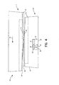
- Figure 2 is a partly schematic top view of the machine tool of Figure 1 comprising a short stationary die and a long displaceable die in a matched position, the stationary die having a recess containing a microchip;
- Figure 3 is a schematic diagram of a second embodiment of a machine tool system in accordance with the invention;
- Figure 4 is a partly schematic top view of the machine tool of Figure 2 comprising a stationary short die and a displaceable long die in a matched position, the stationary die having a recess containing a sensor and/or a microchip and/or a piezo electric power source;
- Figure 5 is a schematic view of the hand-held electronic reader of Figures 1 and 3;
- Figures 6a through 6d are a schematic representation of a cold heading process utilizing a third embodiment of a machine tool system in accordance with the invention; and
- Figure 7 is a perspective view, partly in section, of a gun drilling machine utilizing a fourth embodiment of a machine tool system in accordance with the invention.
- With reference to the drawings, wherein like numerals represent like parts throughout the figures, a
stationary die 10 and amoveable die 12 are employed to roll a thread on a workpiece to produce a finished screw by a reciprocating flat die method. The reciprocatingmoveable die 12 moves relative to thestationary die 10 in the direction of thearrows 14 in Figures 2 and 4 to define a rolling cycle. As the workpiece rolls longitudinally between the starting andfinal ends stationary die 10, a thread is formed on the workpiece. - As illustrated in Figures 2 and 4, the
dies opposing faces dies dies - A starter finger (not illustrated) engages the workpiece blank to ensure that the moving
die 12 picks up the blank and starts the rolling process. For most applications, as the workpiece starts at the startingend die dwell sections dies dwell section - For each rolling cycle there is an associated pressure cycle. As described above, the sharpness of the threads and the thread width vary along the length of the dies 10, 12. Consequently, the pressure force which is exerted on the workpiece by the dies 10, 12 varies as the workpiece progresses through the rolling cycle. An ideal pressure cycle may be calculated and compared to the observed pressure cycle of an operating thread rolling system as a means of monitoring its performance. For example, the IMPAX/SK 3000 ™ process monitoring system monitors and displays the rolling pressure force over each rolling cycle of the thread rolling system. The ideal pressure cycle is displayed simultaneously so that the operator is provided with real-time information on deviation from optimum system operating conditions.
- The IMPAX/SK 3000 ™ process monitoring system utilizes a piezo-electric sensing device mounted in a die adjusting block to sense the pressure exerted on the workpiece by the dies. Other conventional thread rolling system process monitoring systems may utilize other sensors and locate these sensors in the die block, the frame, or the yoke.
- Conventional process monitoring systems may be utilized in several different ways. A persistent deviation between the measured pressure cycle and the ideal pressure cycle generally indicates that the thread rolling system setup is improper. When this occurs, the operator may adjust the thread rolling system setup to minimize or eliminate such deviations and thereby optimize the system performance. A deviation may indicate that a faulty screw was produced during the rolling cycle in which the deviation was observed. When this occurs, the operator may check the output of the thread rolling system to verify the quality of the product.
- With reference to Figures 1 and 2, a
first embodiment 30 of a machine tool system in accordance with the invention includes a cold formingtool 32, such as a pair of flat thread rolling dies 10, 12, having an embedded electronic device such as amicrochip 34. Preferably, themicrochip 34 is positioned in arecess 36 in thestationary die 10 and is mounted within therecess 36 by asealant material 38, such as potting compound or epoxy, which seals therecess 36 against infiltration by particulate matter and liquids. Anantenna 40 extending from themicrochip 34 may also be disposed within thesealant material 38. Alternatively, an electrical orfiber optic lead 42 may extend from themicrochip 34, through thesealant material 38, to at least the surface of thestationary die 10. - The
microchip 34 includes at least amemory portion 44 and adata transmission portion 46. Thememory portion 44 has sufficient storage capacity to store tool identification and design data which does not change over the lifetime of the tool and tool operating data which is updated as the tool is used in the manufacturing process. Permanent tool data for a thread rolling die set may include the customer part number, the manufacturer part number, manufacturing information, set-up information such as an optimum rolling force curve, and the effective lifetime expressed as a number of rolling cycles. Operating data for a thread rolling die set 10, 12 may include the date/time of each set-up, the date/time of each run, the number of rolling cycles in each run, the number of set-up adjustments in each run, abnormal force incidents, wear pattern documentation by run, and the tool life remaining expressed as a number of rolling cycles. Themicrochip 34 stores the permanent data and the operating data and communicates this data when queried by an electronic reader. Thedata transmission portion 46 includes all circuit components and/or software that is required to transmit and receive the operating data. It should be appreciated that any electronic device having at least the memory anddata transmission portions tool 32 may be used in the present invention. - The cold forming
machine 48 in which the cold formingtool 32 is mounted includes aprocess monitoring system 50 having anelectronic reader 52, which communicates with themicrochip 34 embedded in thecold forming tool 32. Such communication may be by microwave, Rf, infrared, or other common radiation of the electromagnetic spectrum. Theprocess monitoring system 50 also includessensors 54 for detecting various operating parameters of the cold formingtool 32. Thesensors 54 may include a sensor, such as a piezo electric sensor capable of sensing the pressure cycle, for detecting operation of the cold forming tool, a temperature sensor for measuring the temperature of the cold forming tool, or a flow detector for monitoring coolant flow to the cold forming tool. Theprocess monitoring system 50 may also include akey pad 56 for inputting data, amonitor 58 for displaying process information, such as the pressure cycle and adata output 60 to a master scheduler system or a machine control system. The processmonitoring system sensors 54 and/or the process monitoring systemkey pad 56 are utilized to input all the parameters which are recorded in themicrochip 34. Amicroprocessor 62 in theprocess monitoring system 50 performs any calculations which are necessary to convert the input signals or transform the sensed or inputted data into the form required for storage in themicrochip 34. For example,microprocessor 62 calculates the remaining effective lifetime of the cold formingtool 32 based on the output of thesensor 54 which detects operation of the cold formingtool 32 and the expected life data and prior use data stored inmicrochip 34. - Preferably, the data/query signal received by the
data transmission portion 46 of themicrochip 34 provides the power required by themicrochip 34 to record the data or respond to the query and therefore an external power source is not required. If the data/query signal does not provide sufficient power, an external power source may be used. A battery mounted in therecess 36 may be used as the external power source. Machine generated vibration power may be utilized as well. Alternatively, a data/power connection may be provided between theprocess monitoring system 50 and microchip viaelectrical lead 42. If an external power source is utilized, themicrochip 34 may be used to perform more power intensive functions. For example, the calculations performed bymicroprocessor 62 could be performed bymicrochip 34. - With reference to Figure 5, the machine tool system also includes a portable, hand-held
electronic reader 64. The hand-heldelectronic reader 64 includes acommunications portion 66, comprising the circuit components and/or software which are required to send and receive data and query signals, adata transmission interface 68 for sending and receiving signals tomicrochip 34, and adata transmission interface 70 for transmitting the stored data to the central control system or some other central monitoring system. The hand-heldelectronic reader 64 also includesmemory 72 for storing the data received in response to the query and may include adisplay 74 for viewing the data received frommicrochip 34. - The hand-held
electronic reader 64 provides flexibility to the subjectmachine tool system 30, 30'. For example, if thedisplay 58 of theprocess monitoring system 50 is at a location which is remote from the cold formingtool 32, the hand-heldelectronic reader 64 allows the operator to query and view the stored data while he is at the cold formingtool 32. - In addition to the cold forming
tools 32 which are in use at any moment in time in thecold forming machines 48, most manufacturers also have a tool crib which containstools 32 which are not actively in use. When the production run of a first type of screw is completed, the first die set 10, 12 (which had been used to produce the first type of screw) is removed from the cold forming machine, a second die set 10, 12 designed for producing the second type of screw is removed from the tool crib and mounted in thecold forming machine 48, and the cold formingmachine 48 commences the production run of the second type of screw. If the first die set 10, 12 has not reached the end of its effective lifetime, it is placed in the tool crib for use in the next production run of the first type of screw. If the first die set 10, 12 has reached the end of its effective lifetime, it is discarded, a new first die set 10, 12 is purchased and placed in the tool crib. Therefore, the tool crib generally contains new die sets and used die sets. With good administrative controls, a manufacturer can easily know which cold formingtools 32 are installed in thecold forming machines 48 and whichcold forming tools 32 are stored in the tool crib. However, it is more difficult for the manufacturer to know which cold formingtools 32 are new and which are used and much more difficult for the manufacturer to know how many more parts may be produced by any one of the used cold formingtools 32. - The hand-held
electronic reader 64 and imbeddedmicrochip 34 provide a means for easily conducting and maintaining an accurate inventory of the manufacturers' cold formingtools 32. More importantly, an inventory conducted with the subject the hand-heldelectronic reader 64 and imbeddedmicrochip 34 includes easily accessible and up to the minute information on the operating history of each of the cold formingtools 32 and the tool remaining life. To conduct the inventory, the user merely passes the hand-heldelectronic reader 64 by each cold formingtool 32. During each pass, thereader 64 queries thetool 32, thetool 32 transmits data stored in themicrochip 34, and the transmitted data is stored inmemory 72. Depending on the capacity of thememory 72, the amount of data which is received from eachtool 32, and the number oftools 32 which must be inventoried, the stored data is downloaded to the central computer periodically during the inventory or at the end of the inventory, and the central computer compiles an inventory list. The data query may be customized depending on the needs of a particular inventory. It should be appreciated that the accuracy and ease of use of this method of inventory is dependent on themicrochip 34 which is embedded in and inseparable from each cold formingtool 32. - The embodiment 30' illustrated in Figures 3 and 4 is very similar to the
first embodiment 30 with the primary exception that asensing device 76, such as a piezo electric device, is mounted in therecess 36 and in communication with themicrochip 34. Consequently, the sensing device signal may be received directly by themicrochip 34 instead of by way of the microprocessor 62' in the process monitoring system. Preferably, the sensing device signal provides the power required by themicrochip 34 to record the data. Alternatively, an external power source such as a battery or an electrical connection with the microprocessor may be used. Similar to the first embodiment, themicrochip 34 may perform any required calculations and data conversion if an external power source is utilized. Otherwise, the process monitoring system microprocessor 62' performs the required calculations and data conversion. The process monitoring system includes an electronic reader 52', additional sensors, a key pad 56', a monitor 58', and a data output 60' to a master scheduler system or a machine control system. - Figures 6a through 6d show the basic sequence of actions in a standard type solid die, double stroke heading machine. In Figure 6a,
wire 78 is shown being fed through the cut off die 80 until it reaches thewire stop 82. By adjusting the location of thisstop 82, the operator determines the length of the blank 86. - In Figure 6b, the
cutoff knife 84 has already cut the blank 86 from the coil and carried it (the blank) to the heading die 88. The knife stroke is set to stop when the blank 86 is centered on the heading die 88. - In Figure 6c, the
first punch 90 comes forward for the first blow. The first andsecond punches first punch 90 begins its forward stroke, it pushes the blank 86 into the heading die 88, right up against the knockout pin 96 (if no extrusion is being done). At this point the blank 86 is subjected to the full force of thefirst punch 90, and begins to flow into its new shape. As the first blow is completed, the extrusion, if any, is done, and the head has been upset into the cone shape, ready for final shaping. - With reference to Figure 6d, the cam-operated mechanism shifts the
punches second punch 92 is aligned with the heading die 88. Thegate 94 comes forward again, the second or finish blow, is struck, and thegate 94 withdraws. As it withdraws, thepunches cone punch 90, is again in position for the new blank. Meanwhile, as thegate 94 is withdrawing, theknockout pin 96 comes forward all the way to the face of the die 88, forcing thefinished part 98 out ahead of it. As thegate 94 reaches its fully withdrawn position, thefinished part 98 is ejected and falls into acollection bin 100. Thecutoff knife 84 is already starting to move a new blank into position, ready to begin the cycle all over again. - As shown in Figures 6c and 6d, a
sensor 102, 102' and amicrochip 104, 104' are mounted in a recess in each of thegate 94 and headingdie 88. Thesensors 102, 102' detect each operation of the cold heading tool and transmit a signal to a process monitoring system for use by the system and for storage in themicrochip 104, 104'. - With reference to Figure 7, gundrilling is a metal removal process utilizing a
drilling machine 108, a highpressure coolant system 110, and a single or a twoflute gundrill 112. The gundrilling process is a controlled operation which offers size, location, finish, and straightness accuracy where critical tolerances are important. Added benefits are scrap reduction, burr-free holes, bottom forming, and blind holes, as well as entry with surfaces other than 90 degrees. Repeatability makes this application feasible on numerically controlled equipment. - In addition to
dedicated gundrilling machines 108, gundrills 112 andcoolant systems 110 are easily integrated with CNC machining centers, lathes, and milling machines, providing users with all the benefits of the process for a relatively small investment. Incorporating gundrills 112 on other types of machinery often requires a short (1 to 2 diameters deep) starter hole to be used in place of the gundrilling machine'sstarter bushing 116. Thegundrill tip 114 is then fed Into the predrilled hole before engaging the spindle. - The
gundrill 112 is a simple, basic tool with three essential parts: thetip 114, theshank 118, and thedriver 120. These parts are brazed together into one correctly aligned unit. - The
tip 114 is the most critical of the three elements. Thetip 114 cuts the hole and maintains precision as it pilots the drill through the part, producing precision holes in one pass. The point or nosegrind has two basic angles that may be varied for optimum results depending on the material to be drilled. These angles must balance the cutting forces, distributing them to the tip's bearing pads to keep the drill concentric. Thetip 114 is slightly larger in diameter than the shank, thus enabling theshank 118 to rotate freely without contacting the hole wall. Through thetip 114 is an oil hole which lines up with the shank's oil channel to facilitate correct flow of coolant at high pressures to the cutting edge. - As shown in Figure 7, a
sensor 122 and amicrochip 124 are mounted in arecess 126 in thegundrill 112. Thesensor 122 detects each operation of thegundrill 112 and transmits a signal to a process monitoring system for use by the system and for storage in themicrochip 124. - It should be appreciated that the heading, threading, and gundrilling machine tools described above may include sensors, other than the load sensors, for monitoring additional system parameters. For example,
sensors Sensors 128 in thecoolant system 110 may be provided to sense coolant flow and/or temperature. - While preferred embodiments have been shown and described, various modifications and substitutions may be made thereto without departing from the scope of the invention as defined by the appended claims. Accordingly, it is to be understood that the present invention has been described by way of illustration and not limitation.
Claims (30)
- A machine tool system (30, 30') comprising:a tool (32) for cold forming a workpiece over an operating cycle, the tool (32) having an electronic device (34) fixedly mounted thereto, the electronic device (34) having means for storing data (44) including identification data for the tool (32) and operating data for the tool (32), the operating data for the tool (32) including tool life remaining for the tool (32);a sensor device (54) which senses each operating cycle of the tool (32); and at least one interface device in communication with the electronic device (34) and the sensor device (54);characterized in thata microprocessor device (62, 62') is provided and is in communication with the interface device, the microprocessor device (62, 62') being configured toreceive operating cycle data from the sensor device (54);determine the expected number of operating cycles over the lifetime of the tool (32);access the identification data and the operating cycle data stored in the electronic device (34);calculate the number of operating cycles that the tool (32) has been used from the operating cycle data;subtract the number of operating cycles that the tool (32) has been used from the determined expected number of operating cycles over the lifetime of the tool (32) to determine the remaining lifetime of the tool (32); andstore the remaining lifetime of the tool (32) in the electronic device (34).
- The machine tool system of claim 1 further comprising a sealant material (38), the tool (32) having an exterior surface and defining a recess (36) extending from the surface, the electronic device (34) being disposed within the recess (36) and encased by the sealant material (38), the electronic device (34) having an antenna (40) extending within the sealant material (38).
- The machine tool system of claim 1 further comprising a sealant material (38), the tool (32) having an exterior surface and defining a recess (36) extending from the surface, the electronic device (34) being disposed within the recess (36) and encased by the sealant material (38), the electronic device (34) having a fiber optic lead (42) extending through the sealant material (38) to at least the surface of the tool (32).
- The machine tool system of claim 1 wherein the at least one interface device includes a process monitoring system (50) having a key pad (56), a monitor (58), and a microprocessor (62).
- The machine tool system of claim 4 wherein the process monitoring system (50) also includes a temperature sensor for measuring the temperature of the tool (32).
- The machine tool system of claim 4 wherein the tool (32) also has a cooling system carrying a flow of coolant through the tool (32) and the process monitoring system (50) also includes a flow detector for monitoring the flow of coolant.
- The machine tool system of claim 4 wherein the at least one interface device also includes a portable electronic reader (64).
- The machine tool system of claim 7 wherein the portable electronic reader (64) includes a first data transmission interface (68) for sending to and receiving signals from the electronic device (34), memory (72) for storing the signals received from the electronic device (34), and a second data transmission interface (70) for transmitting the stored signals to the process monitoring system (50).
- The machine tool system of claim 8 wherein the portable electronic reader (64) also includes a display (74) for viewing the signals received from the electronic device (34).
- The machine tool system of claim 1 wherein the electronic device (34) and the interface device each have a communication portion (46, 52), the communication portion (52) of the interface device including means for transmitting a data/query signal, the communication portion (46) of the electronic device (34) having means for receiving the data/query signal and powering the means for storing data (44) with the data/query signal.
- The machine tool system of claim 1 further comprising a power source mounted to the tool (32).
- The machine tool system of claim 1 wherein the tool (32) includes a punch (90, 92), a die (88), and a ram (94), the sensor device (54) comprises first and second sensors (102, 102'), and the electronic device (34) comprises a first microchip (104'), the die (88) and ram (94) each defining a recess, the first sensor (102') and the first microchip (104') being mounted within the recess of the die (88), the second sensor (102') being mounted within the recess of the ram (94).
- The machine tool system of claim 12 wherein the electronic device (34) also comprises a second microchip (104) mounted within the recess of the ram (94).
- The machine tool system of claim 1 wherein the tool (32) is a gundrill (112) defining a recess (126), the sensor (122) being mounted within the recess (126) of the gundrill (112).
- The machine tool system of claim 14 wherein the electronic device (124) is mounted within the recess (126) of the gundrill (112).
- The machine tool system of claim 1 wherein the identification data for the tool (32) is selected from customer part number, manufacturer part number, manufacturing information, set-up information, effective lifetime, and any combination thereof.
- The machine tool system of claim 16 wherein the set-up information comprises an optimum rolling force curve.
- The machine tool system of claim 16 wherein the effective lifetime is a predetermined number of rolling cycles.
- The machine tool system of claim 1 wherein the tool is a rolling die and the operating data for the tool (32) includes parameters selected from date/time of each set-up, date/time of each run, number of rolling cycles experienced in each run, number of set-up adjustments experienced in each run, abnormal force incidents, wear pattern by run, and any combination thereof.
- The machine tool system of claim 1 wherein the tool is a rolling die and the tool life remaining is computed by subtracting the number of rolling cycles experienced by the tool (32) from a predetermined number of rolling cycles.
- The machine tool system of claim 10 wherein there are no other sources of power connected to the electronic device (34).
- The machine tool system of claim 11 wherein the power source is a battery.
- The machine tool system of claim 11 wherein the sensor device is a piezo electric device (54), said piezo electric device (54) emitting a signal indicative of the operating cycle of the tool (32), said signal powering the means for storing data (44), whereby said piezo electric device (54) is the power source.
- A method of monitoring the life cycle of a cold forming tool (32) in a cold forming system (30, 30'), the tool (32) having an electronic device (34) fixedly mounted thereto, the method comprising the steps of:storing identification data for the tool (32) in the electronic device (34);sensing each operating cycle of the tool (32) with an operating cycle sensor device (54) and transmitting operating cycle data from the operating signal sensor device (54);receiving and storing the operating cycle data in the electronic device (34);determining the expected number of operating cycles over the lifetime of the tool (32);accessing the identification data and the operating cycle data stored in the electronic device (34);calculating the number of operating cycles that the tool (32) has been used from the operating cycle data;subtracting the number of operating cycles that the tool (32) has been used from the determined expected number of operating cycles over the lifetime of the tool (32) to determine the remaining lifetime of the tool (32); andstoring the remaining lifetime of the tool (32) in the electronic device (34).
- The method of claim 24 wherein the cold forming system (30, 30') also has a process monitoring system (50), the method further comprising the steps of:receiving the operating cycle data in the process monitoring system (50); andtransmitting the operating cycle data from the process monitoring system (50) to the electronic device (34).
- The method of claim 25 wherein the cold forming system (30, 30') further has a temperature sensor, the method further comprising the steps of:sensing the temperature of the tool (32); andtransmitting a signal corresponding to the sensed temperature of the tool (32) to the process monitoring system (50).
- The method of claim 25 further comprising the steps of:accessing the identification data and the operating cycle data stored in the electronic device (34) with the process monitoring system (50); anddisplaying the identification data and the operating cycle data at the process monitoring system (50).
- The method of claim 24 further comprising the step of accessing the identification data and the operating cycle data stored in the electronic device (34) with a portable reader (64).
- The method of claim 28 further comprising the step of recording the identification data and operating cycle data in the portable reader (64).
- The method of claim 28 further comprising the step of displaying the identification data and operating cycle data at the portable reader (64).
Applications Claiming Priority (3)
| Application Number | Priority Date | Filing Date | Title |
|---|---|---|---|
| US18616900P | 2000-02-29 | 2000-02-29 | |
| US186169P | 2000-02-29 | ||
| PCT/US2001/006379 WO2001064365A1 (en) | 2000-02-29 | 2001-02-28 | Smart machine tool system |
Publications (3)
| Publication Number | Publication Date |
|---|---|
| EP1259335A1 EP1259335A1 (en) | 2002-11-27 |
| EP1259335A4 EP1259335A4 (en) | 2005-08-24 |
| EP1259335B1 true EP1259335B1 (en) | 2007-10-17 |
Family
ID=22683907
Family Applications (1)
| Application Number | Title | Priority Date | Filing Date |
|---|---|---|---|
| EP01914563A Expired - Lifetime EP1259335B1 (en) | 2000-02-29 | 2001-02-28 | Smart machine tool system |
Country Status (14)
| Country | Link |
|---|---|
| US (1) | US6947800B2 (en) |
| EP (1) | EP1259335B1 (en) |
| JP (1) | JP2003525485A (en) |
| KR (1) | KR100487712B1 (en) |
| CN (1) | CN100475373C (en) |
| AT (1) | ATE375827T1 (en) |
| AU (2) | AU3993601A (en) |
| BR (1) | BR0108770A (en) |
| CA (1) | CA2401161C (en) |
| DE (1) | DE60130971T2 (en) |
| ES (1) | ES2295143T3 (en) |
| MX (1) | MXPA02008426A (en) |
| PL (1) | PL199559B1 (en) |
| WO (1) | WO2001064365A1 (en) |
Cited By (1)
| Publication number | Priority date | Publication date | Assignee | Title |
|---|---|---|---|---|
| EP4068019A1 (en) * | 2021-04-01 | 2022-10-05 | Lisa Dräxlmaier GmbH | Device and method for processing the detected state variables of a punching process |
Families Citing this family (36)
| Publication number | Priority date | Publication date | Assignee | Title |
|---|---|---|---|---|
| WO2002061512A2 (en) * | 2001-01-30 | 2002-08-08 | Endress + Hauser Process Solutions Ag | Method for maintaining and managing a manufacturing facility |
| US6775624B2 (en) * | 2001-10-19 | 2004-08-10 | International Business Machines Corporation | Method and apparatus for estimating remaining life of a product |
| DE10202820C1 (en) * | 2002-01-25 | 2003-03-13 | Fette Wilhelm Gmbh | Set of punches and/or dies for tablet presses is provided with encoded information covering at least the identity of the set, the identity of each punch or die, and their critical dimensions |
| DE10207764B4 (en) * | 2002-02-23 | 2005-11-17 | Wilhelm Fette Gmbh | Method for controlling the assembly of individual components and / or assemblies of a tableting machine |
| US7110918B2 (en) * | 2003-11-05 | 2006-09-19 | Shoplogix Inc. | Self-contained system and method for remotely monitoring machines |
| AT502843B1 (en) * | 2004-02-02 | 2009-08-15 | Schoeller Bleckmann Oilfield T | DRILL AND DRILLING METHOD |
| DE102004045783B4 (en) | 2004-09-21 | 2019-09-12 | Peter Schöberl | Thermoforming mold |
| US20060082010A1 (en) * | 2004-10-19 | 2006-04-20 | Saggese Stefano M | Intelligent molding environment and method of controlling applied clamp tonnage |
| US7580771B2 (en) * | 2004-10-19 | 2009-08-25 | Husky Injection Molding Systems Ltd. | Intelligent molding environment and method of configuring a molding system |
| US20060129269A1 (en) * | 2004-12-15 | 2006-06-15 | Xerox Corporation | Processes for using a memory storage device in conjunction with tooling |
| US20060129268A1 (en) * | 2004-12-15 | 2006-06-15 | Xerox Corporation | Tool data chip |
| US7275802B2 (en) * | 2005-03-03 | 2007-10-02 | Hewlett-Packard Development Company, L.P. | Cleaner |
| GB2426849B (en) * | 2005-05-16 | 2010-12-08 | Circuitmaster Designs Ltd | A system for monitoring and controlling operation of a machine having a detachable component |
| CA2642334A1 (en) * | 2006-02-16 | 2007-08-23 | Shoplogix Inc. | System and method for managing manufacturing information |
| DE102006036974A1 (en) * | 2006-08-08 | 2007-04-19 | Daimlerchrysler Ag | Shaping tool with shaping body, device for mounting shaping body in presses and sensor units useful in shaping processes has sensor units and communication unit mounted on shaping body |
| DE102006056214B4 (en) * | 2006-11-29 | 2019-02-14 | Kuka Deutschland Gmbh | Industrial robot with a tool or sensor and method |
| EP2381649B1 (en) * | 2007-05-07 | 2014-08-20 | Vorne Industries, Inc. | Method and system for extending the capabilities of embedded devices through network clients |
| US8643539B2 (en) * | 2008-11-19 | 2014-02-04 | Nokomis, Inc. | Advance manufacturing monitoring and diagnostic tool |
| US9205587B2 (en) | 2012-08-08 | 2015-12-08 | Synventive Molding Solutions, Inc. | Flow control apparatus and method |
| US9387616B2 (en) * | 2012-08-03 | 2016-07-12 | Otto Männer Innovation GmbH | Hot runner injection molding apparatus with additional controller |
| ITMO20140338A1 (en) * | 2014-11-19 | 2016-05-19 | Paolo Antonini | MOLD FOR THE FORMING OF ARTICLES, SEMI-FINISHED OR SIMILAR PRODUCTS |
| JP6267152B2 (en) * | 2015-04-14 | 2018-01-24 | ファナック株式会社 | Tool conveying apparatus and processing system provided with gripping force measuring means of tool holding means of tool magazine |
| US20170245361A1 (en) * | 2016-01-06 | 2017-08-24 | Nokomis, Inc. | Electronic device and methods to customize electronic device electromagnetic emissions |
| US11130166B2 (en) | 2016-10-07 | 2021-09-28 | Reed Machinery, Inc. | Cylindrical tool matching system |
| US10448864B1 (en) | 2017-02-24 | 2019-10-22 | Nokomis, Inc. | Apparatus and method to identify and measure gas concentrations |
| US10068455B1 (en) * | 2017-04-13 | 2018-09-04 | Steven Label Corporation | Machine press data monitoring and analysis system |
| JP6988890B2 (en) * | 2017-05-25 | 2022-01-05 | 日本電気株式会社 | Processing equipment, processing methods and programs |
| CN107649706B (en) * | 2017-10-18 | 2023-09-15 | 中北大学 | Vibration cutting device for deep hole machining |
| IT201800002485A1 (en) * | 2018-02-08 | 2019-08-08 | Gd Spa | Automatic product processing machine and corresponding control method |
| US11489847B1 (en) | 2018-02-14 | 2022-11-01 | Nokomis, Inc. | System and method for physically detecting, identifying, and diagnosing medical electronic devices connectable to a network |
| NL2020658B1 (en) * | 2018-03-23 | 2019-10-02 | Alt Tech B V | Improved Die Cutting System and Tool Information Management System therefore |
| EP3650969A1 (en) * | 2018-11-07 | 2020-05-13 | Siemens Aktiengesellschaft | System and method for delivery of procedural knowledge for the autonomous use of tools |
| CN114555349A (en) * | 2019-09-27 | 2022-05-27 | 科施股份公司 | Apparatus and method for monitoring a tablet press, preferably during operation, by means of a measuring device attached to the punch |
| US20210173020A1 (en) | 2019-12-10 | 2021-06-10 | Barnes Group Inc. | Wireless Sensor |
| KR102447182B1 (en) * | 2020-03-17 | 2022-09-23 | 가부시키가이샤 하이탓쿠 | gun drill machine |
| CN117291582B (en) * | 2023-11-27 | 2024-03-29 | 合肥宝康自动化系统有限公司 | Industrial production interconnection monitoring system based on data analysis |
Family Cites Families (8)
| Publication number | Priority date | Publication date | Assignee | Title |
|---|---|---|---|---|
| FR2722597B1 (en) * | 1994-07-18 | 1996-08-14 | Kodak Pathe | DEVICE FOR MONITORING THE PARAMETERS OF A MANUFACTURING PROCESS |
| US5564298A (en) * | 1994-11-01 | 1996-10-15 | Aluminum Company Of America | Die tool and press monitor and product quality analysis apparatus and method |
| US5622069A (en) * | 1996-03-11 | 1997-04-22 | Oberg Industries, Inc. | Stamping die with attached plc |
| US5941111A (en) * | 1997-06-05 | 1999-08-24 | Pressco Technology, Inc. | Die set with sunken load cells |
| US6260427B1 (en) * | 1997-07-28 | 2001-07-17 | Tri-Way Machine Ltd. | Diagnostic rule tool condition monitoring system |
| US6047579A (en) * | 1998-04-17 | 2000-04-11 | The Minster Machine Company | RF tag attached to die assembly for use in press machine |
| US6546297B1 (en) * | 1998-11-03 | 2003-04-08 | Robertshaw Controls Company | Distributed life cycle development tool for controls |
| US6101857A (en) * | 1999-04-06 | 2000-08-15 | Oberg Industries | Apparatus for monitoring and controlling progressive punch press production of articles and associated method |
-
2001
- 2001-02-28 JP JP2001563252A patent/JP2003525485A/en active Pending
- 2001-02-28 DE DE60130971T patent/DE60130971T2/en not_active Expired - Fee Related
- 2001-02-28 MX MXPA02008426A patent/MXPA02008426A/en active IP Right Grant
- 2001-02-28 EP EP01914563A patent/EP1259335B1/en not_active Expired - Lifetime
- 2001-02-28 AT AT01914563T patent/ATE375827T1/en not_active IP Right Cessation
- 2001-02-28 WO PCT/US2001/006379 patent/WO2001064365A1/en active IP Right Grant
- 2001-02-28 US US10/203,956 patent/US6947800B2/en not_active Expired - Fee Related
- 2001-02-28 AU AU3993601A patent/AU3993601A/en active Pending
- 2001-02-28 CA CA002401161A patent/CA2401161C/en not_active Expired - Fee Related
- 2001-02-28 CN CNB018056857A patent/CN100475373C/en not_active Expired - Fee Related
- 2001-02-28 KR KR10-2002-7011362A patent/KR100487712B1/en not_active IP Right Cessation
- 2001-02-28 AU AU2001239936A patent/AU2001239936B2/en not_active Ceased
- 2001-02-28 ES ES01914563T patent/ES2295143T3/en not_active Expired - Lifetime
- 2001-02-28 BR BR0108770-3A patent/BR0108770A/en not_active IP Right Cessation
- 2001-02-28 PL PL357509A patent/PL199559B1/en not_active IP Right Cessation
Cited By (1)
| Publication number | Priority date | Publication date | Assignee | Title |
|---|---|---|---|---|
| EP4068019A1 (en) * | 2021-04-01 | 2022-10-05 | Lisa Dräxlmaier GmbH | Device and method for processing the detected state variables of a punching process |
Also Published As
| Publication number | Publication date |
|---|---|
| BR0108770A (en) | 2002-11-26 |
| PL357509A1 (en) | 2004-07-26 |
| EP1259335A4 (en) | 2005-08-24 |
| CA2401161A1 (en) | 2001-09-07 |
| ATE375827T1 (en) | 2007-11-15 |
| JP2003525485A (en) | 2003-08-26 |
| KR100487712B1 (en) | 2005-05-06 |
| CN100475373C (en) | 2009-04-08 |
| KR20020091107A (en) | 2002-12-05 |
| CN1406158A (en) | 2003-03-26 |
| PL199559B1 (en) | 2008-09-30 |
| EP1259335A1 (en) | 2002-11-27 |
| MXPA02008426A (en) | 2002-12-13 |
| AU3993601A (en) | 2001-09-12 |
| WO2001064365A1 (en) | 2001-09-07 |
| CA2401161C (en) | 2006-10-03 |
| DE60130971D1 (en) | 2007-11-29 |
| DE60130971T2 (en) | 2008-07-17 |
| US6947800B2 (en) | 2005-09-20 |
| US20030014150A1 (en) | 2003-01-16 |
| AU2001239936B2 (en) | 2004-09-09 |
| ES2295143T3 (en) | 2008-04-16 |
Similar Documents
| Publication | Publication Date | Title |
|---|---|---|
| EP1259335B1 (en) | Smart machine tool system | |
| US7883303B2 (en) | Machine tool spindle structure capable of monitoring working state in real time | |
| EP2735400B1 (en) | An arrangement for controlling the process of rotary chip removing machining of a workpiece, and a cutting tool for rotary chip removing machining | |
| US8365642B2 (en) | Closed-loop CNC machine system and method | |
| US7206657B2 (en) | Real-time measurement of tool forces and machining process model parameters | |
| US20090234490A1 (en) | Smart Machining System and Smart Tool Holder Therefor | |
| US5535498A (en) | Hole probe method | |
| CN101084475A (en) | Machine and control system | |
| EP3544766B1 (en) | Tool holder for a machining tool of a machine tool, and measuring device | |
| CN101322084A (en) | Method and control device for determination of the time duration before a machine element requires servicing | |
| CN107580531A (en) | Determine the method left of cutting tool and the rotatable tool fixture for cutting tool | |
| KR20100106226A (en) | Deep hole machining method and deep hole machining device | |
| US4854161A (en) | Method for diagnosing cutting tool dullness | |
| US20200361008A1 (en) | Method for operating a core drilling machine, and core drilling machine and core drill bit for carrying out the method | |
| EP2468438B1 (en) | Device for drilling or boring openings | |
| EP1091822B1 (en) | Electronically triggered surface sensor unit | |
| Tsai et al. | On-line identification of thermally-induced convex deformation of the workpiece in surface grinding |
Legal Events
| Date | Code | Title | Description |
|---|---|---|---|
| PUAI | Public reference made under article 153(3) epc to a published international application that has entered the european phase |
Free format text: ORIGINAL CODE: 0009012 |
|
| 17P | Request for examination filed |
Effective date: 20020816 |
|
| AK | Designated contracting states |
Kind code of ref document: A1 Designated state(s): AT BE CH CY DE DK ES FI FR GB GR IE IT LI LU MC NL PT SE TR |
|
| AX | Request for extension of the european patent |
Free format text: AL;LT;LV;MK;RO;SI |
|
| A4 | Supplementary search report drawn up and despatched |
Effective date: 20050706 |
|
| RIC1 | Information provided on ipc code assigned before grant |
Ipc: 7B 21D 55/00 B Ipc: 7B 21C 51/00 A Ipc: 7B 21H 3/06 B Ipc: 7G 06F 19/00 B |
|
| GRAP | Despatch of communication of intention to grant a patent |
Free format text: ORIGINAL CODE: EPIDOSNIGR1 |
|
| GRAS | Grant fee paid |
Free format text: ORIGINAL CODE: EPIDOSNIGR3 |
|
| GRAA | (expected) grant |
Free format text: ORIGINAL CODE: 0009210 |
|
| AK | Designated contracting states |
Kind code of ref document: B1 Designated state(s): AT BE CH CY DE DK ES FI FR GB GR IE IT LI LU MC NL PT SE TR |
|
| REG | Reference to a national code |
Ref country code: GB Ref legal event code: FG4D |
|
| REG | Reference to a national code |
Ref country code: CH Ref legal event code: EP |
|
| REG | Reference to a national code |
Ref country code: IE Ref legal event code: FG4D |
|
| REF | Corresponds to: |
Ref document number: 60130971 Country of ref document: DE Date of ref document: 20071129 Kind code of ref document: P |
|
| REG | Reference to a national code |
Ref country code: CH Ref legal event code: NV Representative=s name: TROESCH SCHEIDEGGER WERNER AG |
|
| REG | Reference to a national code |
Ref country code: SE Ref legal event code: TRGR |
|
| REG | Reference to a national code |
Ref country code: ES Ref legal event code: FG2A Ref document number: 2295143 Country of ref document: ES Kind code of ref document: T3 |
|
| PG25 | Lapsed in a contracting state [announced via postgrant information from national office to epo] |
Ref country code: PT Free format text: LAPSE BECAUSE OF FAILURE TO SUBMIT A TRANSLATION OF THE DESCRIPTION OR TO PAY THE FEE WITHIN THE PRESCRIBED TIME-LIMIT Effective date: 20080317 |
|
| PG25 | Lapsed in a contracting state [announced via postgrant information from national office to epo] |
Ref country code: AT Free format text: LAPSE BECAUSE OF FAILURE TO SUBMIT A TRANSLATION OF THE DESCRIPTION OR TO PAY THE FEE WITHIN THE PRESCRIBED TIME-LIMIT Effective date: 20071017 |
|
| ET | Fr: translation filed | ||
| PG25 | Lapsed in a contracting state [announced via postgrant information from national office to epo] |
Ref country code: DK Free format text: LAPSE BECAUSE OF FAILURE TO SUBMIT A TRANSLATION OF THE DESCRIPTION OR TO PAY THE FEE WITHIN THE PRESCRIBED TIME-LIMIT Effective date: 20071017 |
|
| PLBE | No opposition filed within time limit |
Free format text: ORIGINAL CODE: 0009261 |
|
| STAA | Information on the status of an ep patent application or granted ep patent |
Free format text: STATUS: NO OPPOSITION FILED WITHIN TIME LIMIT |
|
| 26N | No opposition filed |
Effective date: 20080718 |
|
| PG25 | Lapsed in a contracting state [announced via postgrant information from national office to epo] |
Ref country code: MC Free format text: LAPSE BECAUSE OF NON-PAYMENT OF DUE FEES Effective date: 20080228 |
|
| PG25 | Lapsed in a contracting state [announced via postgrant information from national office to epo] |
Ref country code: GR Free format text: LAPSE BECAUSE OF FAILURE TO SUBMIT A TRANSLATION OF THE DESCRIPTION OR TO PAY THE FEE WITHIN THE PRESCRIBED TIME-LIMIT Effective date: 20080118 |
|
| PG25 | Lapsed in a contracting state [announced via postgrant information from national office to epo] |
Ref country code: FI Free format text: LAPSE BECAUSE OF FAILURE TO SUBMIT A TRANSLATION OF THE DESCRIPTION OR TO PAY THE FEE WITHIN THE PRESCRIBED TIME-LIMIT Effective date: 20071017 |
|
| PGFP | Annual fee paid to national office [announced via postgrant information from national office to epo] |
Ref country code: ES Payment date: 20090226 Year of fee payment: 9 Ref country code: IE Payment date: 20090305 Year of fee payment: 9 |
|
| PGFP | Annual fee paid to national office [announced via postgrant information from national office to epo] |
Ref country code: NL Payment date: 20090224 Year of fee payment: 9 |
|
| PGFP | Annual fee paid to national office [announced via postgrant information from national office to epo] |
Ref country code: CH Payment date: 20090225 Year of fee payment: 9 Ref country code: GB Payment date: 20090227 Year of fee payment: 9 |
|
| PG25 | Lapsed in a contracting state [announced via postgrant information from national office to epo] |
Ref country code: CY Free format text: LAPSE BECAUSE OF FAILURE TO SUBMIT A TRANSLATION OF THE DESCRIPTION OR TO PAY THE FEE WITHIN THE PRESCRIBED TIME-LIMIT Effective date: 20071017 |
|
| PGFP | Annual fee paid to national office [announced via postgrant information from national office to epo] |
Ref country code: DE Payment date: 20090331 Year of fee payment: 9 Ref country code: IT Payment date: 20090224 Year of fee payment: 9 Ref country code: SE Payment date: 20090227 Year of fee payment: 9 Ref country code: TR Payment date: 20090216 Year of fee payment: 9 |
|
| PGFP | Annual fee paid to national office [announced via postgrant information from national office to epo] |
Ref country code: BE Payment date: 20090408 Year of fee payment: 9 |
|
| PGFP | Annual fee paid to national office [announced via postgrant information from national office to epo] |
Ref country code: FR Payment date: 20090217 Year of fee payment: 9 |
|
| PG25 | Lapsed in a contracting state [announced via postgrant information from national office to epo] |
Ref country code: LU Free format text: LAPSE BECAUSE OF NON-PAYMENT OF DUE FEES Effective date: 20080228 |
|
| BERE | Be: lapsed |
Owner name: PCC SPECIALTY PRODUCTS, INC. Effective date: 20100228 |
|
| REG | Reference to a national code |
Ref country code: NL Ref legal event code: V1 Effective date: 20100901 |
|
| REG | Reference to a national code |
Ref country code: CH Ref legal event code: PL |
|
| GBPC | Gb: european patent ceased through non-payment of renewal fee |
Effective date: 20100228 |
|
| PG25 | Lapsed in a contracting state [announced via postgrant information from national office to epo] |
Ref country code: LI Free format text: LAPSE BECAUSE OF NON-PAYMENT OF DUE FEES Effective date: 20100228 Ref country code: CH Free format text: LAPSE BECAUSE OF NON-PAYMENT OF DUE FEES Effective date: 20100228 |
|
| EUG | Se: european patent has lapsed | ||
| REG | Reference to a national code |
Ref country code: FR Ref legal event code: ST Effective date: 20101029 |
|
| PG25 | Lapsed in a contracting state [announced via postgrant information from national office to epo] |
Ref country code: FR Free format text: LAPSE BECAUSE OF NON-PAYMENT OF DUE FEES Effective date: 20100301 Ref country code: NL Free format text: LAPSE BECAUSE OF NON-PAYMENT OF DUE FEES Effective date: 20100901 Ref country code: IE Free format text: LAPSE BECAUSE OF NON-PAYMENT OF DUE FEES Effective date: 20100228 |
|
| PG25 | Lapsed in a contracting state [announced via postgrant information from national office to epo] |
Ref country code: DE Free format text: LAPSE BECAUSE OF NON-PAYMENT OF DUE FEES Effective date: 20100901 Ref country code: BE Free format text: LAPSE BECAUSE OF NON-PAYMENT OF DUE FEES Effective date: 20100228 |
|
| PG25 | Lapsed in a contracting state [announced via postgrant information from national office to epo] |
Ref country code: GB Free format text: LAPSE BECAUSE OF NON-PAYMENT OF DUE FEES Effective date: 20100228 Ref country code: IT Free format text: LAPSE BECAUSE OF NON-PAYMENT OF DUE FEES Effective date: 20100228 |
|
| REG | Reference to a national code |
Ref country code: ES Ref legal event code: FD2A Effective date: 20110405 |
|
| PG25 | Lapsed in a contracting state [announced via postgrant information from national office to epo] |
Ref country code: ES Free format text: LAPSE BECAUSE OF NON-PAYMENT OF DUE FEES Effective date: 20110323 |
|
| PG25 | Lapsed in a contracting state [announced via postgrant information from national office to epo] |
Ref country code: ES Free format text: LAPSE BECAUSE OF NON-PAYMENT OF DUE FEES Effective date: 20100301 |
|
| PG25 | Lapsed in a contracting state [announced via postgrant information from national office to epo] |
Ref country code: SE Free format text: LAPSE BECAUSE OF NON-PAYMENT OF DUE FEES Effective date: 20100301 |
|
| PG25 | Lapsed in a contracting state [announced via postgrant information from national office to epo] |
Ref country code: TR Free format text: LAPSE BECAUSE OF NON-PAYMENT OF DUE FEES Effective date: 20100228 |