EP1259060B1 - Imaging device for generating a number of image points in a projection line - Google Patents
Imaging device for generating a number of image points in a projection line Download PDFInfo
- Publication number
- EP1259060B1 EP1259060B1 EP02009280A EP02009280A EP1259060B1 EP 1259060 B1 EP1259060 B1 EP 1259060B1 EP 02009280 A EP02009280 A EP 02009280A EP 02009280 A EP02009280 A EP 02009280A EP 1259060 B1 EP1259060 B1 EP 1259060B1
- Authority
- EP
- European Patent Office
- Prior art keywords
- diode laser
- laser light
- light source
- light sources
- line
- Prior art date
- Legal status (The legal status is an assumption and is not a legal conclusion. Google has not performed a legal analysis and makes no representation as to the accuracy of the status listed.)
- Expired - Lifetime
Links
Images


Classifications
-
- B—PERFORMING OPERATIONS; TRANSPORTING
- B41—PRINTING; LINING MACHINES; TYPEWRITERS; STAMPS
- B41J—TYPEWRITERS; SELECTIVE PRINTING MECHANISMS, i.e. MECHANISMS PRINTING OTHERWISE THAN FROM A FORME; CORRECTION OF TYPOGRAPHICAL ERRORS
- B41J2/00—Typewriters or selective printing mechanisms characterised by the printing or marking process for which they are designed
- B41J2/435—Typewriters or selective printing mechanisms characterised by the printing or marking process for which they are designed characterised by selective application of radiation to a printing material or impression-transfer material
- B41J2/447—Typewriters or selective printing mechanisms characterised by the printing or marking process for which they are designed characterised by selective application of radiation to a printing material or impression-transfer material using arrays of radiation sources
- B41J2/45—Typewriters or selective printing mechanisms characterised by the printing or marking process for which they are designed characterised by selective application of radiation to a printing material or impression-transfer material using arrays of radiation sources using light-emitting diode [LED] or laser arrays
-
- B—PERFORMING OPERATIONS; TRANSPORTING
- B41—PRINTING; LINING MACHINES; TYPEWRITERS; STAMPS
- B41C—PROCESSES FOR THE MANUFACTURE OR REPRODUCTION OF PRINTING SURFACES
- B41C1/00—Forme preparation
-
- B—PERFORMING OPERATIONS; TRANSPORTING
- B41—PRINTING; LINING MACHINES; TYPEWRITERS; STAMPS
- B41J—TYPEWRITERS; SELECTIVE PRINTING MECHANISMS, i.e. MECHANISMS PRINTING OTHERWISE THAN FROM A FORME; CORRECTION OF TYPOGRAPHICAL ERRORS
- B41J2/00—Typewriters or selective printing mechanisms characterised by the printing or marking process for which they are designed
- B41J2/435—Typewriters or selective printing mechanisms characterised by the printing or marking process for which they are designed characterised by selective application of radiation to a printing material or impression-transfer material
- B41J2/47—Typewriters or selective printing mechanisms characterised by the printing or marking process for which they are designed characterised by selective application of radiation to a printing material or impression-transfer material using the combination of scanning and modulation of light
- B41J2/471—Typewriters or selective printing mechanisms characterised by the printing or marking process for which they are designed characterised by selective application of radiation to a printing material or impression-transfer material using the combination of scanning and modulation of light using dot sequential main scanning by means of a light deflector, e.g. a rotating polygonal mirror
- B41J2/473—Typewriters or selective printing mechanisms characterised by the printing or marking process for which they are designed characterised by selective application of radiation to a printing material or impression-transfer material using the combination of scanning and modulation of light using dot sequential main scanning by means of a light deflector, e.g. a rotating polygonal mirror using multiple light beams, wavelengths or colours
-
- H—ELECTRICITY
- H04—ELECTRIC COMMUNICATION TECHNIQUE
- H04N—PICTORIAL COMMUNICATION, e.g. TELEVISION
- H04N1/00—Scanning, transmission or reproduction of documents or the like, e.g. facsimile transmission; Details thereof
- H04N1/04—Scanning arrangements, i.e. arrangements for the displacement of active reading or reproducing elements relative to the original or reproducing medium, or vice versa
- H04N1/047—Detection, control or error compensation of scanning velocity or position
- H04N1/053—Detection, control or error compensation of scanning velocity or position in main scanning direction, e.g. synchronisation of line start or picture elements in a line
-
- B—PERFORMING OPERATIONS; TRANSPORTING
- B41—PRINTING; LINING MACHINES; TYPEWRITERS; STAMPS
- B41C—PROCESSES FOR THE MANUFACTURE OR REPRODUCTION OF PRINTING SURFACES
- B41C1/00—Forme preparation
- B41C1/10—Forme preparation for lithographic printing; Master sheets for transferring a lithographic image to the forme
- B41C1/1075—Mechanical aspects of on-press plate preparation
-
- H—ELECTRICITY
- H04—ELECTRIC COMMUNICATION TECHNIQUE
- H04N—PICTORIAL COMMUNICATION, e.g. TELEVISION
- H04N1/00—Scanning, transmission or reproduction of documents or the like, e.g. facsimile transmission; Details thereof
- H04N1/04—Scanning arrangements, i.e. arrangements for the displacement of active reading or reproducing elements relative to the original or reproducing medium, or vice versa
- H04N1/06—Scanning arrangements, i.e. arrangements for the displacement of active reading or reproducing elements relative to the original or reproducing medium, or vice versa using cylindrical picture-bearing surfaces, i.e. scanning a main-scanning line substantially perpendicular to the axis and lying in a curved cylindrical surface
-
- H—ELECTRICITY
- H04—ELECTRIC COMMUNICATION TECHNIQUE
- H04N—PICTORIAL COMMUNICATION, e.g. TELEVISION
- H04N1/00—Scanning, transmission or reproduction of documents or the like, e.g. facsimile transmission; Details thereof
- H04N1/04—Scanning arrangements, i.e. arrangements for the displacement of active reading or reproducing elements relative to the original or reproducing medium, or vice versa
- H04N1/19—Scanning arrangements, i.e. arrangements for the displacement of active reading or reproducing elements relative to the original or reproducing medium, or vice versa using multi-element arrays
- H04N1/191—Scanning arrangements, i.e. arrangements for the displacement of active reading or reproducing elements relative to the original or reproducing medium, or vice versa using multi-element arrays the array comprising a one-dimensional array, or a combination of one-dimensional arrays, or a substantially one-dimensional array, e.g. an array of staggered elements
- H04N1/1911—Simultaneously or substantially simultaneously scanning picture elements on more than one main scanning line, e.g. scanning in swaths
-
- H—ELECTRICITY
- H04—ELECTRIC COMMUNICATION TECHNIQUE
- H04N—PICTORIAL COMMUNICATION, e.g. TELEVISION
- H04N2201/00—Indexing scheme relating to scanning, transmission or reproduction of documents or the like, and to details thereof
- H04N2201/04—Scanning arrangements
- H04N2201/047—Detection, control or error compensation of scanning velocity or position
- H04N2201/04753—Control or error compensation of scanning position or velocity
- H04N2201/04758—Control or error compensation of scanning position or velocity by controlling the position of the scanned image area
- H04N2201/04767—Control or error compensation of scanning position or velocity by controlling the position of the scanned image area by controlling the timing of the signals, e.g. by controlling the frequency o phase of the pixel clock
- H04N2201/04781—Controlling the phase of the signals
- H04N2201/04786—Controlling a start time, e.g. for output of a line of data
Definitions
- the invention relates to an imaging device with a number of light sources, each having a distance s i , the index i counting the light sources, to an object line, for generating pixels of the light sources in a projection line of the object line on a printing form, which at least with a velocity component v moves perpendicular to the direction defined by the projection line and tangential to the surface of the printing plate, and with a driving means for switching each individual light source.
- a plurality of light sources typically lasers, in particular diode laser arrays, are frequently used.
- Such a compact beam laser light source is in the document EP 1168 813 A2 disclosed.
- each individual light source or each individual emitter is switched on, or the quantities influencing light intensity are set or predetermined for each pressure point to be set in such a way that each individual emitter generates a pixel with a specific light intensity.
- an imaging optics for projecting the light emitted by the light sources onto the printing form, frequently with a change in the direction of propagation of the light or under beam shaping is also frequently provided.
- the pixels of the light sources on the printing form it is desirable for the pixels of the light sources on the printing form to lie in a projection line, typically when the printing form is recorded on a so-called printing plate cylinder or printing plate cylinder, parallel to the cylinder axis. If the pixels are not on a projection line or, in particular, not parallel to the cylinder axis, image errors can occur on the printing form.
- a compact laser diode array with reduced asymmetry is disclosed. It is contemplated to reduce the smile effect of the laser diode bar by associating a plurality of thermal load elements for the plurality of individual diode light sources.
- the thermal load elements are similar to the individual laser diode light sources except that their output power is blocked.
- Each thermal load element is brought into direct contact with its associated individual laser diodes, so that an efficient heat transfer can take place.
- By passing a variable current through the load element the operating temperature of the individual laser light source can be changed or adjusted. Consequently, the position of two laser light sources to each other by means of different currents can be achieved by their respective associated heat load.
- a disadvantage of a temperature influence of the smile effect is, for example, that the wavelength of the radiation emitted by the laser light source is changed. Furthermore, fluctuations in the temperature control lead to shifts in the position of the laser diode compared to the array axis.
- the light sources are turned on and off after a certain time.
- the emitters are triggered by a trigger signal or trigger signal at a certain triggering time. It is already known that, since the printing form having a velocity component v is perpendicular to the main direction of propagation of the light emitted by the light source
- the object line lies in the object plane.
- the object line may be a curve in the object plane with curved and straight sections, without limitation of generality, a straight object line will subsequently be considered.
- the individual light sources or emitters each have a distance s i , wherein i counts down the individual emitters, wherein at least two light sources have a different distance from the object line. Typically, this distance is not zero within the desired or required precision or can not be neglected.
- the laser diode bar has a plurality of light sources which emit light of different divergence in two mutually orthogonal axes, a so-called slow and a so-called fast axis, and illuminate an array of microlenses.
- the arrangement of microlenses collimates the light in the direction of the slow axis.
- An optical element adjacent to the microlenses breaks the light in the fast axis direction.
- an optical element In the direction of the slow axis, an optical element focuses the emitted one Moves light fixed direction, the pixel of a light source is depending on the triggering time on the printing form at a position with coordinates, which are a function of the triggering time.
- this fact is reflected in the document US Pat. No. 5,174,205 Device for the control of an imaging device for a printing form, which moves during the imaging process relative to the imaging device exploited.
- the image information is stored in a first memory, while correction data for the control of the light sources are in a second memory.
- the correction data is used to vary the time intervals between imaging shots of the light sources to compensate for deviations between the measured position of the printing form compared to the imaging head and the actual position.
- an imaging device incorporates a number of light sources
- a variation of the control of individual light sources thus serves at most to the position of the pixel on which at least one speed component v perpendicular to change or influence the main propagation direction of the direction determined by the light source emitted light moving form.
- an imaging of a printing form can take place by means of laser light sources lying along an object line via a transmission pattern of a lighted modulator or via the modulation of the pump currents when the laser light sources can be individually modulated.
- the surface of a printing form is moved with a velocity component v perpendicular to one through the projection line of the laser light sources or the exit points of the laser light from the modulator.
- a write head is described with a diode laser array individually addressable by a driver.
- the diode lasers are arranged along a straight line, which is preferably aligned parallel to the axis of rotation of a cylinder on which pixels in a projection line on a film are to be described.
- the cylinder is rotatable so that the projected pixels move relatively and tangentially to the surface of the film.
- the object of the present invention is to provide a printing device imaging device which has a number of pixels which are projected onto a projection line of an object line, with a plurality of diode laser light sources on a diode laser bar, at least two diode lasers on the diode laser bar being at a different distance from the object line.
- imaging device having the features according to claim 1 and by a method for generating pixels according to claim 5.
- Advantageous embodiments and further developments of the imaging device according to the invention and of the method according to the invention are characterized in the subclaims.
- the imaging device comprises a number of light sources for generating pixels of the light sources in a projection line on a printing form.
- the light sources each have a distance s i , where the subscript i counts down the light sources, to an object line in the object plane defined by the light sources.
- the end mirrors of the laser resonators essentially lie in one plane and can thus define an object plane.
- an object plane can also be a plane spatially behind an imaging optics arranged downstream of the light sources.
- the projection line comprises the dots of the printing form on which the image of the object line comes to rest on the printing form at a first point in time.
- Projection line and object line have a projection ratio k.
- a pixel of a light source is to be understood as that point on the printing form to which the light emitted by the light source strikes at a certain point in time while the light source is actually switched on.
- the printing form moves at least at a velocity component v perpendicular to the direction defined by the object line and tangent to the surface of the printing form, at least in the vicinity of the projection points of the light sources.
- the projection line defined as described above moves with the printing form.
- the imaging device is assigned a control device for switching each individual light source.
- the switching comprises switching on each individual light source, which then emits light with a certain intensity in a specific time interval and switching off the light source.
- Triggering is understood in this context to mean that at least the switching on is carried out.
- Intensity and exposure time for a pixel are a function of the data to be imaged. By means of the guided over the printing form pixel a pressure point is generated.
- the inventive device is characterized in that the control device of the light sources is associated with a time delay device which shifts the triggering time of the driving device for each light source as a function of the respective distance s i of the light source to the object line.
- an advantageous object line is a straight line in the object plane, in particular it is advantageous if the light sources lie in a half-plane of the object line, which by means of the object line extending straight line is limited.
- the imaging device is characterized in that the control device is associated with a time delay device, which relative to the triggering time, ie the time of switching, a first light source whose projection point is on the projection line of the object line, so that is generated by the triggering of the first light source, a pixel on the projection line, timewise different every other light source of the number of light sources such or triggert that also the corresponding or associated pixel is generated on the projection line of the object line, if the corresponding or associated projection point of the other light source is on the projection line.
- the triggering time of the first light source is at or after the first time that defines the position of the projection line on the printing form.
- a first light source in the imaging device according to the invention with a number of light sources is triggered when its projection point comes to lie on the projection line of the object line, so that the corresponding or associated pixel lies on the projection line.
- the simultaneous triggering of each other light source in the imaging device would generally result in each pixel of each other light source not lying on the projection line, because in general the projection points at the triggering time of the first light source are not on the projection line of the object line.
- each projection point of each other light source changes its position on the printing plate, so also its position relative to the pixel of the first light source set to the printing form pressure point or defined at the first time projection line of the object line on the printing form. After a certain time each projection point of every other light source passes the projection line, so that the Triggering of this light source leads to an imaging by a pixel on the projection line of the object line.
- Imaging device is described without limitation of generality as a delayed release at the time of triggering a first light source.
- This representation is based on the idea that the first light source is the one whose projection point, due to the relative movement between the imaging device and the printing form, first reaches the projection line of the object line.
- an object line is preferably selected, for which it applies that all the light sources lie in a half-plane of the object plane, which is bounded by the straight line passing through the contra-lateral line.
- each triggering signal or triggering signal for triggering an imaging for each emitter is temporally shifted by a delay device or a delay circuit, so that the deviation of the position of the individual light sources is compensated to a line object in the plane defined by the light sources.
- the light sources arranged on a diode laser bar in the imaging device according to the invention are a one-dimensional array of diode lasers.
- the imaging device may comprise imaging optics.
- This imaging optics is preferably objects with a projection ratio k depict. It can also be provided that beam-shaping elements, light deflection elements or light-guiding elements, such as mirrors, optical waveguides or the like, or elements for polarization rotation of the light are provided.
- the imaging optics include elements for divergence or astigmatism correction of the light sources and / or aberration correction elements.
- the printing form can be clamped or picked up on a cylinder.
- the projection line of the object line preferably runs substantially parallel to the cylinder axis about which the printing form can be rotated.
- the imaging device is movable substantially parallel to the cylinder axis.
- the printing form moves uniformly with a velocity component v perpendicular to the direction determined by the object line and tangential to the surface of the printing form.
- the velocity component v is essentially constant.
- the imaging device can be used to generate a field of pressure points through rows of pixels, in particular for a field in which adjacent pressure points to be generated have a distance h. If the Distance s i of a light source is greater than the n-fold distance h / k adjacent pressure points, where n is a natural number and k is the projection ratio, the control of the relevant light source with the image information of the generating pressure point, which is the smallest distance to the projection line Item line.
- the driving device then switches the said light source so that in the delay time interval points on the printing plate have essentially passed the distance (ks i -nh), where k is the projection ratio between object line and projection line and n is int (s i k / h), ie the largest natural multiple of h, for which nh is smaller than s i k.
- the inventive method for generating pixels of a number of light sources, each having a distance s i , wherein the index i counts the light sources, to an object line in the plane defined by the light sources, in a projection line of the object line on a printing form, which Moving at least with a velocity component v perpendicular to the direction defined by the object line and tangential to the printing form surface, comprises the following steps.
- the exposure is triggered by a first light source when its projection point is on the projection line of the object line.
- a second light source is delayed in time to trigger the first light source triggered such that the corresponding pixel of the second light source is on the projection line of the object line, so if the corresponding projection point of the second light source passes the projection line.
- An analogous procedure is provided for each additional light source in the imaging device with a number of light sources.
- the imaging device or with the method according to the invention for generating pixels from a number of light sources, it is possible to easily compensate the smile effect of diode laser arrays without accepting a reduction in the beam quality.
- the delay device in the form of a programmable logic, a design is also possible for a large number of emitters, for example greater than 20 individual light sources a very compact design possible.
- the number of emitters or light sources is a prime number or a prime power
- the spacing of the emitter projection points is a multiple of h, the multiple being a prime common to said prime or prime power.
- a printing press according to the invention with a feeder, at least one printing unit and a delivery comprises at least one printing unit which has an imaging device according to the invention.
- FIG. 1 The exemplary sketch shown shows the location of a number of light sources to a line of objects.
- the FIG. 1 shows, by way of example and without limitation of generality, seven light sources 12 and one object line 14. For each light source 12, the distance s is the perpendicular from the center 18 of the light source 12 to the object line 14. In most cases, the article line 14 will be substantially parallel to a boundary line of the emitter surface of the light source 12 in which FIG. 1 However, the general case, in which also the distances s of the individual light sources are different in size, shown.
- the FIG. 2 schematically represents a preferred embodiment of the imaging device according to the invention with a time delay device for different circuit of individual light sources.
- the imaging module 10 consists of a single controllable array of a number of light sources 12 typically laser light sources, in particular diode laser arrays.
- the light sources 12 are not located on an object line 14, but each have an individual distance to this object line 14.
- the FIG. 2 By way of example, the general case is shown that not all the light sources 12 lie in a half-plane of the object line, which is bounded by the straight line passing through the object line.
- the light beams 24 emitted by the light sources 12 are imaged onto pixels 210 on a printing form 28 by means of imaging optics 26.
- the pixels 210 to a projection line 16 which corresponds to the imaging of the object line 14 by the imaging optics 26 at a first time, an individual Distance up.
- the distance of a specific pixel 210 to the projection line 16 will be proportional to the distance of the pixel 210 generating light source 12 to the object line 14 with the proportionality factor of the projection ratio k of the imaging optics 26 in the absence of aberrations of the imaging optics.
- the light sources 12 in the imaging module 10 can be used in continuous laser mode. To generate individual light packets, the laser emission is correspondingly suppressed or interrupted for a certain time interval. Since the printing form 28 moves at least tangentially to the surface of the printing plate 28 relative to a speed component v to the imaging device, the pixels 210 of the light sources 12 are at different triggering times at different coordinate positions on the surface of the printing plate 28 when the light sources 12 are all triggered simultaneously The projection line 16 of the object line 14 moves with the printing form 28.
- the imaging optics 26 can have both reflective, transmissive, refractive or similar optical components. Preferably, these are micro-optical components, ie components which influence the light emitted by an individual light source 12, while the light from the other light sources 12 remains unaffected by this component.
- the imaging optics 26 can have both a magnifying and reducing as well as in the two directions parallel and perpendicular to the active zone of the laser different magnifications, which is particularly advantageous for divergence and / or aberration correction.
- the surface of the printing form 28 is changed in its physical and / or chemical properties by the laser radiation, so that image information for a pressure point is written by the exposure with a certain intensity and during a certain time interval.
- the imaging module 10 is located on a cooling element 212, for example, a copper heat sink with cooling water flow.
- the Imaging module 10 is connected to a drive device 216 by means of a line for power supply and control 214.
- the drive device 216 has individual components with which it is possible to control or regulate the individual light sources 12 of the array separately from each other.
- the cooling element 212 is connected to the temperature control 220.
- the embodiment of the imaging device according to the invention which in FIG. 2 is shown comprises a delay device 222, which is integrated in a compact design with the imaging module 10.
- the delay device 222 is linked to the control device 216 via the connection 224, that is to say it is assigned to it.
- the delay device 222 preferably comprises a programmable logic or an ASIC, an application-specific integrated circuit.
- the FIG. 3 shows an embodiment of the imaging device according to the invention with a time delay device for imaging a printing form, which is accommodated on a rotatable cylinder.
- the imaging module 30 has, for example, three light sources, so that three light beams 32 are generated, which are imaged by means of the imaging optics 34 onto three pixels 310 on the printing form 38.
- the three pixels have an individual distance to a projection line 18. Without limiting the generality, a projection line 18 is shown, for which it holds that the three pixels 310 lie in a half plane of the projection plane which is bounded by the straight line passing through the projection line 18.
- the printing form 38 is located on a cylinder 36, which is rotatable about its axis of symmetry 35. This rotation is indicated by the arrow R.
- the imaging module 30 can be moved substantially parallel to the axis of symmetry 35 of the cylinder 36 in substantially linear ways, which is marked with the double arrow T.
- the cylinder 36 rotates with printing form 38 received thereon in accordance with the rotational movement R, and the imaging module 30 translates along the cylinder 36 according to the direction of movement T.
- the result is an illustration which rotates helically about the axis of symmetry 35 of the cylinder 36.
- the path of the projection points or pixels 310 is indicated by the lines 312.
- the imaging module 30 is linked to a connection 314 with a control unit 316.
- the control unit 316 comprises a delay device 318 and a drive device 320.
- FIGS. 4, 5 . 6 and 7 serve to illustrate by way of example without limitation of generality, such as with the imaging device according to the invention with a number of light sources, each having a distance s i , the index i counting the light sources, to an object line in the plane defined by the light sources, to Generation of pixels of the light sources in a projection line of the object line on a printing form, which moves at least with a velocity component v perpendicular to that through the object line and tangent to the surface of the printing form, pressure points generated by pixels on the projection line or a field of pressure points by rows becomes.
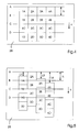
- the FIG. 4 is an exemplary sketch for explaining the notation used with respect to the position to be imaged pressure points on a printing form 28.
- the FIG. 4 is based without limitation on the generality of four emitters or light sources, which here for example generate a field of 4 x 4 pressure points through pixels of the light sources on the printing form.
- a regular Cartesian field is to be described.
- other patterns to imprinting pressure points are conceivable.
- the extension of a pressure point or the distance between adjacent pressure points to each other, measured from one center to the next center is designated by h.
- the pressure points are shown as squares; the actual shape is determined by the shape of the imaging light beam with its process parameters such as intensity, exposure time, relative speed between printing form and imaging light beam, and the like.
- the pressure points in the field are denoted by a number-letter combination: The number corresponds to the index, which counts the individual light sources, in particular lasers, while the letter in the order of the alphabet counts the time-sequential imaging steps.
- the FIG. 4 shows a first projection line A, a second projection line B, a third projection line C and a fourth projection line D, which pass the projection points of the four emitters or light sources not shown here in succession, when the printing form with a velocity component v in the arrow direction relative to the light sources moved to a comprehensive imaging module.
- a trigger or switching signal is generated for triggering the imaging by the pixel, so that a pressure point is set.
- FIG. 5 is a schematic representation of an exemplary layer of pixels without compensation on the printing plate 28 shown by the time delay device of the imaging device according to the invention.
- the projection point of the second light source happens to be the first projection line A in time here, without restricting the generality. If all the light sources are driven at the same time, the pixels of the objects are due to the individual distance of each light source to an object line in the plane defined by the light sources shifted from other light sources compared to the starting edge of the pixel 2A or added.
- the pixels generated by the first light source have a first offset L1
- the pixels produced by the third light source have a third offset L3
- the pixels generated by the fourth light source have a fourth offset L4. Is exemplary in the FIG. 5 have shown that the pixels of the fourth light source are more than one pressure point h from the corresponding projection line.
- FIG. 6 is a schematic representation of the exemplary position of pixels without compensation on the printing plate 28 by changing the control of the light sources with those projection points or pixels whose distance is greater than the pressure point distance.
- position deviations greater than two pixel lengths h are compensated for by temporally shifting the data in accordance with two imaging steps. By means of this procedure of shifting data, it can be achieved that all position deviations are smaller than one pixel length h.
- Exemplary is in FIG. 6 the distance of the fourth pixel to the fourth residual offset L4 'is reduced, in other words L4' in this case corresponds to the remainder of the division (L4 mod h).
- the FIG. 7 is a schematic representation of the position of pixels with compensation by delayed control of the light sources after a triggering time of a temporally considered first light source, here for example the second light source.
- the data transfer and the triggering of the light sources after a triggering time of a first light source light sources can be delayed.
- the desired field of pressure points will be generated by iteration for each additional projection line, as described in the following FIG. 4 is shown generated.
- the delay device should be operated at a signal frequency that is a multiple of the frequency of the original drive signal.
- the realization of the displacement by delayed activation is effected by the delay device, which has, for example, a programmable logic, an ASIC, a discrete electronics or the like.
- the delay electronics are provided with the distances s i , the index i counting the light sources, and the projection ratio k between the object line and the projection line in a suitable form, for example by storage in a memory unit.
- the deceleration device can determine from these indications, the velocity component v of the relative movement between the printing form and the imaging device with a known velocity profile of the printing form, for example a uniform movement, starting values for counters, which are each assigned to a light source. At a fixed clock frequency of the delay device elapses depending on the counter start a certain time interval, was counted down to zero, so that a delayed triggering of the control of the corresponding light source can be triggered upon reaching the zero value of the counter.
- the distances s i can be determined as part of a calibration or measurement for an object line in the object plane. It is clear in this context that the distances s i of the light sources can be converted to a first object line with simple arithmetic at distances to a second object line.
Abstract
Description
Die Erfindung betrifft eine Bebilderungseinrichtung mit einer Anzahl von Lichtquellen, welche jeweils einen Abstand si, wobei der Index i die Lichtquellen abzählt, zu einer Gegenstandslinie aufweisen, zur Erzeugung von Bildpunkten der Lichtquellen in einer Projektionslinie der Gegenstandslinie auf einer Druckform, welche sich wenigstens mit einer Geschwindigkeitskomponente v senkrecht zu der durch die Projektionslinie festgelegten Richtung und tangential zur Oberfläche der Druckform bewegt, und mit einer Ansteuerungseinrichtung zum Schalten jeder einzelnen Lichtquelle.The invention relates to an imaging device with a number of light sources, each having a distance s i , the index i counting the light sources, to an object line, for generating pixels of the light sources in a projection line of the object line on a printing form, which at least with a velocity component v moves perpendicular to the direction defined by the projection line and tangential to the surface of the printing plate, and with a driving means for switching each individual light source.
Zur Bebilderung von Druckformen, die eine, ebene oder gekrümmte Fläche bilden, sei es in einem Druckformbelichter oder einem Direct Imaging Druckwerk einer Druckmaschine, wird häufig eine Mehrzahl von Lichtquellen, typischerweise Laser, insbesondere Diodenlaserarrays, eingesetzt. Eine derartige kompakte Mchrstrahllaserlichtquelle ist im Dokument
Licht auf einen räumlichen Lichtmodulator derart, dass das Licht jeder punktförmigen Lichtquelle die ganze aktive Fläche des räumlichen Lichtmodulators bestrahlt. Es ist ein weiteres optisches Element vorgesehen, welches das Licht in Richtung der schnellen Achse fokussiert, sodass die gewünschte Fleckgröße in Richtung der schnellen Achse erzeugt wird. Das im Dokument
In der
Zur Erzeugung von Bildpunkten werden die Lichtquellen eingeschaltet und nach einer gewissen Zeit wieder ausgeschaltet. Typischerweise werden die Emitter durch ein TriggerSignal oder Auslösungssignal zu einem gewissen Auslösezeitpunkt angesteuert. Es ist bereits bekannt, dass, da sich die Druckform mit einer Geschwindigkeitskomponente v senkrecht zu der hauptsächlichen Ausbreitungsrichtung des von der Lichtquelle emittiertenTo generate pixels, the light sources are turned on and off after a certain time. Typically, the emitters are triggered by a trigger signal or trigger signal at a certain triggering time. It is already known that, since the printing form having a velocity component v is perpendicular to the main direction of propagation of the light emitted by the light source
Eine wesentlichen Ursache, aufgrund der die Bildpunkte der Lichtquellen nicht auf einer Projektionslinie auf der Druckform liegen, ist, dass die Lichtquellen zwar mit hinreichender Präzision in einer Gegenstandsebene liegen, in dieser aber nicht auf einer Gegenstandslinie angeordnet sind. Die Gegenstandslinie liegt in der Gegenstandsebene. Grundsätzlich kann die Gegenstandslinie eine Kurve in der Gegenstandsebene mit gekrümmten und geraden Abschnitten sein, ohne Einschränkung der Allgemeinheit wird in der Folge eine gerade Gegenstandslinie betrachtet. Mit anderen Worten: Zu einer Gegenstandslinie weisen die einzelnen Lichtquellen oder Emitter jeweils einen Abstand si auf, wobei i die einzelnen Emitter abzählt, wobei wenigstens zwei Lichtquellen einen unterschiedlichen Abstand zu der Gegenstandslinie besitzen. Typischerweise ist dieser Abstand im Rahmen der gewünschten oder erforderlichen Präzision nicht Null oder kann nicht vernachlässigt werden.A significant cause, due to the fact that the pixels of the light sources are not on a projection line on the printing form, is that the light sources are indeed with sufficient precision in an object plane, but are not arranged in this on a subject line. The object line lies in the object plane. Basically, the object line may be a curve in the object plane with curved and straight sections, without limitation of generality, a straight object line will subsequently be considered. In other words, to an object line, the individual light sources or emitters each have a distance s i , wherein i counts down the individual emitters, wherein at least two light sources have a different distance from the object line. Typically, this distance is not zero within the desired or required precision or can not be neglected.
Diese Tatsache kann häufig bei Lasern als Lichtquellen, insbesondere bei Diodenlaserarrays auftreten, welche ein oder mehrere Halbleiterbauelemente auf einem Trägerelement umfassen. Häufig treten s-förmige oder u-förmige Verbiegungen eines Halbleiterbauelementes auf, wenn mittels eines Lötprozesses das die Emitter umfassende Halbleiterbauelement auf einem ebenen Trägerelement, wie beispielsweise einem Kupferkühlkörper aufgebracht wird. Dieser herstellungsbedingte Fehler wird auch als Smile-Effekt des Laserdiodenbarrens bezeichnet.This fact can frequently occur with lasers as light sources, in particular with diode laser arrays, which comprise one or more semiconductor components on a carrier element. Often occur s-shaped or U-shaped bends of a semiconductor device, if by means of a soldering process, the semiconductor device comprising the emitter is applied to a planar support member, such as a copper heat sink. This production-related error is also referred to as the smile effect of the laser diode bar.
Aus der Literatur sind Vorrichtungen bekannt, welche eine Reduktion oder einen Ausgleich dieses bei Laserdiodenbarren auftretenden Smile-Effekts ermöglichen. Beispielsweise wird in der
In diesem Zusammenhang sei auch das Dokument
In diesen Dokumenten des Standes der Technik mit verzögerter Auslösung wird davon ausgegangen, dass eine Bebilderungseinrichtung mit einer Anzahl von Lichtquellen verwendet wird, mit welcher Bildpunkte auf der Druckform erzeugt werden können, welche mit hinreichender Präzision bereits in einer Projektionslinie auf der Druckform liegen, Eine Variation der Ansteuerung einzelner Lichtquellen dient also allenfalls dazu, die Lage des Bildpunktes auf der sich wenigstens mit einer Geschwindigkeitskomponente v senkrecht zu der hauptsächlichen Ausbreitungsrichtung des von der Lichtquelle emittierten Lichtes festgelegten Richtung bewegten Druckform zu verändern oder zu beeinflussen.In these prior art delayed release documents, it is believed that an imaging device incorporates a number of light sources A variation of the control of individual light sources thus serves at most to the position of the pixel on which at least one speed component v perpendicular to change or influence the main propagation direction of the direction determined by the light source emitted light moving form.
Des Weiteren ist aus dem Dokument
Im Dokument
Im Dokument
Aufgabe der vorliegenden Erfindung ist es, eine Bebilderungseinrichtung für eine Druckform zur schaffen, welche eine Anzahl von Bildpunkten, die auf eine Projektionslinie einer Gegenstandslinie angeordnet sind, mit einer Anzahl von Diodenlaserlichtquellen auf einem Diodenlaserbarren erzeugt, wobei wenigstens zwei Diodenlaser auf dem Diodenlaserbarren einen unterschiedlichen Abstand zu der Gegenstandslinie aufweisen.The object of the present invention is to provide a printing device imaging device which has a number of pixels which are projected onto a projection line of an object line, with a plurality of diode laser light sources on a diode laser bar, at least two diode lasers on the diode laser bar being at a different distance from the object line.
Diese Aufgabe wird durch eine Bebilderungseinrichtung mit den Merkmalen gemäß Anspruch 1 und durch ein Verfahren zur Erzeugung von Bildpunkten gemäß Anspruch 5 gelöst. Vorteilhafte Ausführungsformen und Weiterbildungen der erfindungsgemäßen Bebilderungseinrichtung und des erfindungsgemäßen Verfahrens sind in den Unteransprüchen charakterisiert.This object is achieved by a imaging device having the features according to claim 1 and by a method for generating pixels according to claim 5. Advantageous embodiments and further developments of the imaging device according to the invention and of the method according to the invention are characterized in the subclaims.
Im Fall von Diodenlaserbarren ist eine wesentliche Ursache für eine ungleichmäßige Lage der Emitter zu einer Gegenstandslinie der sogenannte Smile-Effekt, wie oben näher beschrieben. Mit der erfindungsgemäßen Bebilderungseinrichtung kann auf einfache Art und Weise der Smile-Effekt kompensiert werden.In the case of diode laser bars, a significant cause of an uneven location of the emitters to an object line is the so-called smile effect, as described in more detail above. With the imaging device according to the invention, the smile effect can be compensated in a simple manner.
Die erfindungsgemäße Bebilderungseinrichtung umfasst eine Anzahl von Lichtquellen zur Erzeugung von Bildpunkten der Lichtquellen in einer Projektionslinie auf einer Druckform. Die Lichtquellen weisen jeweils einen Abstand si, wobei der Index i die Lichtquellen abzählt, zu einer Gegenstandslinie in der Gegenstandsebene, welche durch die Lichtquellen definiert ist, auf. Beispielsweise liegen bei Laserlichtquellen auf einem Substrat die Endspiegel der Laserresonatoren im wesentlichen in einer Ebene und können damit eine Gegenstandsebene festlegen. Alternativ dazu kann eine Gegenstandsebene auch eine Ebene räumlich hinter einer den Lichtquellen nachgeordneten Abbildungsoptik sein. Die Projektionslinie umfasst die Punkte der Druckform, auf denen das Bild der Gegenstandslinie zu einem ersten Zeitpunkt auf der Druckform zu liegen kommt. Projektionslinie und Gegenstandslinie weisen ein Projektionsverhältnis k auf. Unter einem Projektionspunkt einer Lichtquelle ist derjenige Punkt auf der Druckform zu verstehen, auf den das von der Lichtquelle emittierte Licht zu einem bestimmten Zeitpunkt fallen würde, wenn diese in besagtem Zeitpunkt eingeschaltet ist. Unter einem Bildpunkt einer Lichtquelle ist derjenige Punkt auf der Druckform zu verstehen, auf den das von der Lichtquelle emittierte Licht zu einem bestimmten Zeitpunkt auftrifft, während die Lichtquelle tatsächlich eingeschaltet ist.The imaging device according to the invention comprises a number of light sources for generating pixels of the light sources in a projection line on a printing form. The light sources each have a distance s i , where the subscript i counts down the light sources, to an object line in the object plane defined by the light sources. For example, in the case of laser light sources on a substrate, the end mirrors of the laser resonators essentially lie in one plane and can thus define an object plane. Alternatively, an object plane can also be a plane spatially behind an imaging optics arranged downstream of the light sources. The projection line comprises the dots of the printing form on which the image of the object line comes to rest on the printing form at a first point in time. Projection line and object line have a projection ratio k. Under a Projection point of a light source is that point on the printing form to understand, to which the light emitted by the light source would fall at a certain time when it is turned on in said time. A pixel of a light source is to be understood as that point on the printing form to which the light emitted by the light source strikes at a certain point in time while the light source is actually switched on.
Die Druckform bewegt sich wenigstens mit einer Geschwindigkeitskomponente v senkrecht zu der durch die Gegenstandslinie festgelegten Richtung und tangential zur Oberfläche der Druckform, wenigstens in der Nähe der Projektionspunkte der Lichtquellen. Folglich bewegt sich die Projektionslinie, die wie oben beschrieben definiert ist, mit der Druckform.The printing form moves at least at a velocity component v perpendicular to the direction defined by the object line and tangent to the surface of the printing form, at least in the vicinity of the projection points of the light sources. As a result, the projection line defined as described above moves with the printing form.
Der Bebilderungseinrichtung ist eine Ansteuerungseinrichtung zum Schalten jeder einzelnen Lichtquelle zugeordnet. Das Schalten umfasst dabei ein Einschalten jeder einzelnen Lichtquelle, welche dann mit einer bestimmten Intensität in einem bestimmten Zeitintervall Licht emittiert und ein Ausschalten der Lichtquelle. Unter Auslösen wird in diesem Zusammenhang verstanden, dass wenigstens das Einschalten vorgenommen wird. Intensität und Belichtungsdauer für einen Bildpunkt sind eine Funktion der zu bebildernden Daten. Mittels des über die Druckform geführten Bildpunktes wird ein Druckpunkt erzeugt.The imaging device is assigned a control device for switching each individual light source. The switching comprises switching on each individual light source, which then emits light with a certain intensity in a specific time interval and switching off the light source. Triggering is understood in this context to mean that at least the switching on is carried out. Intensity and exposure time for a pixel are a function of the data to be imaged. By means of the guided over the printing form pixel a pressure point is generated.
Die erfindungsgemäße Einrichtung zeichnet sich dadurch aus, dass der Ansteuerungseinrichtung der Lichtquellen eine zeitliche Verzögerungseinrichtung zugeordnet ist, welche den Auslösezeitpunkt der Ansteuerungseinrichtung für jede Lichtquelle in Abhängigkeit vom jeweiligen Abstand si der Lichtquelle zu der Gegenstandslinie verschiebt.The inventive device is characterized in that the control device of the light sources is associated with a time delay device which shifts the triggering time of the driving device for each light source as a function of the respective distance s i of the light source to the object line.
Ohne Einschränkung der Allgemeinheit ist eine vorteilhafte Gegenstandslinie eine gerade Linie in der Gegenstandsebene, insbesondere ist vorteilhaft, wenn die Lichtquellen in einer Halbebene der Gegenstandslinie liegen, welche mittels der durch die Gegenstandslinie verlaufende Gerade begrenzt ist.Without limiting the generality, an advantageous object line is a straight line in the object plane, in particular it is advantageous if the light sources lie in a half-plane of the object line, which by means of the object line extending straight line is limited.
In anderen Worten ausgedrückt, zeichnet sich die erfindungsgemäße Bebilderungseinrichtung dadurch aus, dass der Ansteuerungseinrichtung eine zeitliche Verzögerungseinrichtung zugeordnet ist, welche relativ zum Auslösezeitpunkt, also dem Zeitpunkt des Einschaltens, einer ersten Lichtquelle, deren Projektionspunkt auf der Projektionslinie der Gegenstandslinie zu liegen kommt, so dass durch das Auslösen der ersten Lichtquelle ein Bildpunkt auf der Projektionslinie erzeugt wird, jede andere Lichtquelle der Anzahl von Lichtquellen zeitlich abweichend derart schaltet oder triggert, dass auch der korrespondierende oder zugehörige Bildpunkt auf der Projektionslinie der Gegenstandslinie erzeugt wird, wenn der korrespondierende oder zugehörige Projektionspunkt der anderen Lichtquelle auf der Projektionslinie liegt. Typischerweise liegt der Auslösezeitpunkt der ersten Lichtquelle an oder nach dem ersten Zeitpunkt, durch den die Lage der Projektionslinie auf der Druckform definiert ist.In other words, the imaging device according to the invention is characterized in that the control device is associated with a time delay device, which relative to the triggering time, ie the time of switching, a first light source whose projection point is on the projection line of the object line, so that is generated by the triggering of the first light source, a pixel on the projection line, timewise different every other light source of the number of light sources such or triggert that also the corresponding or associated pixel is generated on the projection line of the object line, if the corresponding or associated projection point of the other light source is on the projection line. Typically, the triggering time of the first light source is at or after the first time that defines the position of the projection line on the printing form.
Mit anderen Worten: Eine erste Lichtquelle in der erfindungsgemäßen Bebilderungseinrichtung mit einer Anzahl von Lichtquellen wird dann ausgelöst, wenn ihr Projektionspunkt auf der Projektionslinie der Gegenstandslinie zu liegen kommt, so dass der korrespondierende oder zugehörige Bildpunkt auf der Projektionslinie liegt. Das gleichzeitige Auslösen jeder anderen Lichtquelle in der Bebilderungseinrichtung würde im allgemeinen dazu führen, dass jeder Bildpunkt jeder anderen Lichtquelle nicht auf der Projektionslinie liegt, weil im allgemeinen die Projektionspunkte am Auslösezeitpunkt der ersten Lichtquelle nicht auf der Projektionslinie der Gegenstandslinie liegen. Da sich aber die Druckform relativ mit einer Geschwindigkeitskomponente v senkrecht zu der durch die Projektionslinie festgelegten Richtung und tangential zur Oberfläche der Druckform bewegt, ändert jeder Projektionspunkt jeder anderen Lichtquelle seine Lage auf der Druckform, also auch seine Lage relativ zum durch den Bildpunkt der ersten Lichtquelle auf die Druckform gesetzten Druckpunkt bzw. zur am ersten Zeitpunkt definierten Projektionslinie der Gegenstandslinie auf der Druckform. Nach einer bestimmten Zeit passiert jeder Projektionspunkt jeder anderen Lichtquelle die Projektionslinie, sodass die Auslösung dieser Lichtquelle zu einer Bebilderung durch einen Bildpunkt auf der Projektionslinie der Gegenstandslinie führt.In other words, a first light source in the imaging device according to the invention with a number of light sources is triggered when its projection point comes to lie on the projection line of the object line, so that the corresponding or associated pixel lies on the projection line. The simultaneous triggering of each other light source in the imaging device would generally result in each pixel of each other light source not lying on the projection line, because in general the projection points at the triggering time of the first light source are not on the projection line of the object line. However, since the printing form moves relative to a velocity component v perpendicular to the direction defined by the projection line and tangent to the surface of the printing plate, each projection point of each other light source changes its position on the printing plate, so also its position relative to the pixel of the first light source set to the printing form pressure point or defined at the first time projection line of the object line on the printing form. After a certain time each projection point of every other light source passes the projection line, so that the Triggering of this light source leads to an imaging by a pixel on the projection line of the object line.
Die zeitlich versetzte Auslösung der einzelnen Lichtquellen in der erfindungsgemäßen. Bebilderungseinrichtung ist ohne Beschränkung der Allgemeinheit als verzögerte Auslösung zum Auslösezeitpunkt einer ersten Lichtquelle beschrieben. Dieser Darstellung liegt die Vorstellung zugrunde, dass als erste Lichtquelle diejenige angesteuert wird, deren Projektionspunkt aufgrund der Relativbewegung zwischen Bebilderungseinrichtung und Druckform als erste die Projektionslinie der Gegenstandslinie erreicht. Bevorzugt wird dabei eine Gegenstandslinie gewählt, für die gilt, dass alle Lichtquellen in einer Halbebene der Gegenstandsebene liegen, welche durch die durch die Gegenslandslinie verlaufende Gerade begrenzt ist. Für den Fachmann ist klar, dass, wenn als erste Lichtquelle eine Lichtquelle bezeichnet wird, deren Bildpunkt auf der Projektionslinie der Gegenstandslinie erst nach Bildpunkten mehrerer anderer Lichtquellen der Bebildungseinrichtung zu liegen kommt, für die mehreren anderen Lichtquellen eine vorauseilende Auslösung erforderlich ist. In der erfindungsgemäßen Bebilderungseinrichtung wird jedes Triggersignal oder Ansteuerungssignal zur Auslösung einer Bebilderung für jeden einzelnen Emitter über eine Verzögerungseinrichtung oder eine Delay-Schaltung zeitlich verschoben, sodass die Abweichung der Lage der einzelnen Lichtquellen zu einer Gegenstandslinie in der durch die Lichtquellen definierten Ebene kompensiert wird.The staggered release of the individual light sources in the invention. Imaging device is described without limitation of generality as a delayed release at the time of triggering a first light source. This representation is based on the idea that the first light source is the one whose projection point, due to the relative movement between the imaging device and the printing form, first reaches the projection line of the object line. In this case, an object line is preferably selected, for which it applies that all the light sources lie in a half-plane of the object plane, which is bounded by the straight line passing through the contra-lateral line. It is clear to the person skilled in the art that if the first light source is a light source whose pixel on the projection line of the object line comes to lie only after pixels of several other light sources of the imaging device, a premature triggering is required for the several other light sources. In the imaging device according to the invention, each triggering signal or triggering signal for triggering an imaging for each emitter is temporally shifted by a delay device or a delay circuit, so that the deviation of the position of the individual light sources is compensated to a line object in the plane defined by the light sources.
Bevorzugt handelt es sich bei den auf einem Diodenlaserbarren angeordneten Lichtquellen in der erfindungsgemaßcn Bebilderungseinrichtung um eindimensionales Array aus Diodenlasern.Preferably, the light sources arranged on a diode laser bar in the imaging device according to the invention are a one-dimensional array of diode lasers.
Zusätzlich kann die erfindungsgemäße Bebilderungseinrichtung eine Abbildungsoptik umfassen. Bevorzugt wird diese Abbildungsoptik Objekte mit einem Projektionsverhältnis k abbilden. Es kann ebenfalls vorgesehen sein, dass strahlformende Elemente, Lichtumlenkelemente oder Lichtleitelemente, wie Spiegel, Lichtwellenleiter oder dergleichen, oder Elemente zur Polarisationsdrehung des Lichtes vorgesehen sind. Typischerweise umfasst die Abbildungsoptik Elemente zur Divergenz- oder Astigmatismuskorrektur der Lichtquellen und/oder Elemente zur Aberrationskorrektur.In addition, the imaging device according to the invention may comprise imaging optics. This imaging optics is preferably objects with a projection ratio k depict. It can also be provided that beam-shaping elements, light deflection elements or light-guiding elements, such as mirrors, optical waveguides or the like, or elements for polarization rotation of the light are provided. Typically, the imaging optics include elements for divergence or astigmatism correction of the light sources and / or aberration correction elements.
In bevorzugter Ausrührungsform kann die Druckform auf einen Zylinder aufgespannt oder aufgenommen werden. Die Projektionslinie der Gegenstandslinie verläuft dabei bevorzugt im Wesentlichen parallel zur Zylinderachse, um welche die Druckform gedreht werden kann. Des Weiteren kann vorgesehen sein, dass die Bebilderungseinrichtung im Wesentlichen parallel zur Zylinderachse bewegbar ist. Durch Rotationsbewegung um und Translationsbewegung entlang der Zylinderachse können alle relevanten, zur Bebilderung vorgesehenen Punkte auf der Druckform erreicht werden.In a preferred embodiment, the printing form can be clamped or picked up on a cylinder. The projection line of the object line preferably runs substantially parallel to the cylinder axis about which the printing form can be rotated. Furthermore, it can be provided that the imaging device is movable substantially parallel to the cylinder axis. By means of rotational movement and translational movement along the cylinder axis, all relevant points for imaging can be achieved on the printing form.
In bevorzugter Ausführung ist vorgesehen, dass sich die Druckform mit einer Geschwindigkeitskomponente v senkrecht zu der durch die Gegenstandslinie festgelegten Richtung und tangential zur Oberfläche der Druckform gleichförmig bewegt. Mit anderen Worten: Die Geschwindigkeitskomponente v ist im wesentlichen konstant. Das bedeutet, dass bei einem Projektionsverhältnis k nach dem Auslösezeitpunkt einer ersten Lichtquelle der erfindungsgemäßen Bebilderungseinrichtung jede andere Lichtquelle der Anzahl von Lichtquellen nach der Zeit ![]()
![]()
Die erfindungsgemäße Bebilderungseinrichtung kann zur Erzeugung eines Feldes von Druckpunkten durch Reihen von Bildpunkten eingesetzt werden, insbesondere für ein Feld, in welchem benachbarte zu erzeugende Druckpunkte einen Abstand h aufweisen. Wenn der Abstand si einer Lichtquelle größer als der n-fache Abstand h/k benachbarter Druckpunkte ist, wobei n eine natürliche Zahl und k das Projektionsverhältnis ist, kann die Ansteuerung der betreffenden Lichtquelle mit der Bildinformation des erzeugenden Druckpunktes, welcher den geringsten Abstand zur Projektionslinie der Gegenstandslinie aufweist, erfolgen. Die Ansteuerungseinrichtung schaltet dann die besagte Lichtquelle derart, dass im Verzögerungszeitintervall Punkte auf der Druckform im Wesentlichen die Strecke (ksi-nh) durchgelegt haben, wobei k das Projektionsverhältnis zwischen Gegenstandslinie und Projektionslinie und n ist Int (si k / h), also das größte natürliche Vielfache von h, für das gilt, dass n h kleiner als si k ist.The imaging device according to the invention can be used to generate a field of pressure points through rows of pixels, in particular for a field in which adjacent pressure points to be generated have a distance h. If the Distance s i of a light source is greater than the n-fold distance h / k adjacent pressure points, where n is a natural number and k is the projection ratio, the control of the relevant light source with the image information of the generating pressure point, which is the smallest distance to the projection line Item line. The driving device then switches the said light source so that in the delay time interval points on the printing plate have essentially passed the distance (ks i -nh), where k is the projection ratio between object line and projection line and n is int (s i k / h), ie the largest natural multiple of h, for which nh is smaller than s i k.
Das erfindungsgemäße Verfahren zur Erzeugung von Bildpunkten von einer Anzahl von Lichtquellen, welche jeweils einen Abstand si, wobei der Index i die Lichtquellen abzählt, zu einer Gegenstandslinie in der durch die Lichtquellen definierten Ebene aufweisen, in einer Projektionslinie der Gegenstandslinie auf einer Druckform, welche wenigstens mit einer Geschwindigkeitskomponente v senkrecht zu der durch die Gegenstandslinie festgelegten Richtung und tangential zur Druckformoberfläche bewegt wird, umfasst dabei die folgenden Schritte. Es wird die Belichtung durch eine erste Lichtquelle ausgelöst, wenn deren Projektionspunkt auf der Projektionslinie der Gegenstandslinie zu liegen kommt. Eine zweite Lichtquelle wird zeitlich verzögert zum Auslösen der ersten Lichtquelle derart ausgelöst, dass auch der korrespondierende Bildpunkt der zweiten Lichtquelle auf der Projektionslinie der Gegenstandslinie liegt, wenn also der korrespondierende Projektionspunkt der zweiten Lichtquelle die Projektionslinie passiert. Es ist ein analoges Vorgehen für jede weitere Lichtquelle in der Bebilderungseinrichtung mit einer Anzahl von Lichtquellen vorgesehen.The inventive method for generating pixels of a number of light sources, each having a distance s i , wherein the index i counts the light sources, to an object line in the plane defined by the light sources, in a projection line of the object line on a printing form, which Moving at least with a velocity component v perpendicular to the direction defined by the object line and tangential to the printing form surface, comprises the following steps. The exposure is triggered by a first light source when its projection point is on the projection line of the object line. A second light source is delayed in time to trigger the first light source triggered such that the corresponding pixel of the second light source is on the projection line of the object line, so if the corresponding projection point of the second light source passes the projection line. An analogous procedure is provided for each additional light source in the imaging device with a number of light sources.
Mit der erfindungsgemäße Bebilderungseinrichtung bzw. mit dem erfindungsgemäßen Verfahren zur Erzeugung von Bildpunkten von einer Anzahl von Lichtquellen ist eine einfach Kompensation des Smile-Effektes von Diodenlaserarrays möglich, ohne eine Reduktion der Strahlqualität in Kauf zu nehmen. Mittels einer Realisation der Verzögerungseinrichtung in Form einer programmierbaren Logik ist auch für eine große Anzahl von Emittern, beispielsweise größer als 20 einzelne Lichtquellen, ein Aufbau in einer sehr kompakten Bauform möglich. Vorteilhaft ist die Anzahl der Emitter oder Lichtquellen eine Primzahl oder eine Prinzahlpotenz und der Abtand der Emitterprojektionspunkte beträgt ein Vielfaches von h, wobei das Vielfache eine teilerfremd zu der genannten Primzahl oder Primzahlpotenz ist.With the imaging device according to the invention or with the method according to the invention for generating pixels from a number of light sources, it is possible to easily compensate the smile effect of diode laser arrays without accepting a reduction in the beam quality. By means of a realization of the delay device in the form of a programmable logic, a design is also possible for a large number of emitters, for example greater than 20 individual light sources a very compact design possible. Advantageously, the number of emitters or light sources is a prime number or a prime power, and the spacing of the emitter projection points is a multiple of h, the multiple being a prime common to said prime or prime power.
Besonders vorteilhaft ist der Einsatz der erfindungsgemäßen Bebilderungseinrichtung in einem Druckformbelichter oder einem Druckwerk, in welchem eine Druckform direkt bebildert werden kann. Eine erfindungsgemäße Druckmaschine mit einem Anleger, wenigstens einem Druckwerk und einem Ausleger umfasst wenigstens ein Druckwerk, welches eine erfindungsgemäße Bebilderungseinrichtung aufweist.Particularly advantageous is the use of the imaging device according to the invention in a printing form setter or a printing unit in which a printing form can be imaged directly. A printing press according to the invention with a feeder, at least one printing unit and a delivery comprises at least one printing unit which has an imaging device according to the invention.
Weitere Vorteile und vorteilhafte Ausführungsformen und Weiterbildungen der Erfindung werden anhand der nachfolgenden Figuren sowie deren Beschreibungen dargestellt. Es zeigt im Einzelnen:
- Figur 1
- eine beispielhafte Skizze zur Erläuterung der der Lage einer Anzahl von Lichtquellen zu einer Gegenstandslinie;
- Figur 2
- eine bevorzugte Ausführungsform der erfindungsgemäßen Bebilderungseinrichtung mit einer zeitlichen Verzögerungseinrichtung zur abweichenden Schaltung der Anzahl von Lichtquellen;
- Figur 3
- eine Ausführungsform der erfindungsgemäßen Bebilderungseinrichtung mit einer zeitlichen Verzögerungseinrichtung zur Bebilderung einer Druckform, welche auf einem rotierbaren Zylinder aufgenommen ist;
- Figur 4
- eine beispielhafte Skizze zur Erläuterung der benutzten Notation hinsichtlich der Lage zu bebildernder Druckpunkte auf einer Druckform;
- Figur 5
- eine schematische Darstellung einer beispielhaften Lage von Bildpunkten ohne Kompensation durch die zeitliche Verzögerungseinrichtung der erfindungsgemäßen Bebilderungseinrichtung auf der Druckform;
- Figur 6
- eine schematische Darstellung der beispielhaften Lage von Bildpunkten ohne Kompensation durch veränderte Ansteuerung derjenigen Bildpunkte, deren Abstand größer als der Druckpunktabstand ist; und
- Figur 7
- eine schematische Darstellung der Lage von Bildpunkten mit Kompensation durch verzögerte Ansteuerung der Lichtquellen.
- FIG. 1
- an exemplary sketch for explaining the position of a number of light sources to a subject line;
- FIG. 2
- a preferred embodiment of the imaging device according to the invention with a time delay means for different circuit of the number of light sources;
- FIG. 3
- an embodiment of the imaging device according to the invention with a time delay device for imaging a printing form, which is accommodated on a rotatable cylinder;
- FIG. 4
- an exemplary sketch for explaining the notation used with respect to the position to be imaged pressure points on a printing form;
- FIG. 5
- a schematic representation of an exemplary layer of pixels without compensation by the time delay device of inventive imaging device on the printing form;
- FIG. 6
- a schematic representation of the exemplary position of pixels without compensation by changing control of those pixels whose distance is greater than the pressure point distance; and
- FIG. 7
- a schematic representation of the position of pixels with compensation by delayed control of the light sources.
Die in
Die
Die Lichtquellen 12 im Bebilderungsmodul 10 können im kontinuierlichen Laserbetrieb eingesetzt werden. Zur Erzeugung einzelner Lichtpakete wird die Laseremission für ein gewisses Zeitintervall entsprechend unterdrückt oder unterbrochen. Da die Druckform 28 sich relativ mit einer Geschwindigkeitskomponente v zur Bebilderungseinrichtung wenigstens tangential zur Oberfläche der Druckform 28 bewegt, liegen die Bildpunkte 210 der Lichtquellen 12, wenn die Lichtquellen 12 alle gleichzeitig ausgelöst werden, zu unterschiedlichen Auslösezeitpunkten an unterschiedlichen Koordinatenpositionen auf der Fläche der Druckform 28. Die Projektionslinie 16 der Gegenstandslinie 14 bewegt sich mit der Druckform 28.The
Die Abbildungsoptik 26 kann sowohl reflektierende, transmittierende, refraktive oder ähnliche optische Komponenten aufweisen. Bevorzugt handelt es sich dabei um mikrooptische Komponenten, also Komponenten, welche das von einer individuellen Lichtquelle 12 emittierte Licht beeinflussen, während das Licht von den anderen Lichtquellen 12 unbeeinflusst durch diese Komponente bleibt. Insbesondere für den Fall, dass die Lichtquellen 12 Laser, insbesondere Diodenlaser, sind, kann die Abbildungsoptik 26 sowohl eine vergrößernde wie auch verkleinernde als auch in den beiden Richtungen parallel und senkrecht zur aktiven Zone der Laser unterschiedliche Abbildungsmaßstäbe besitzen, welches insbesondere vorteilhaft zur Divergenz- und/oder Aberrationskorrektur ist. Die Oberfläche der Druckform 28 wird in ihren physikalischen und/oder chemischen Eigenschaften durch die Laserstrahlung verändert, sodass durch die Belichtung mit einer bestimmten Intensität und während eines bestimmten Zeitintervalls Bildinformation für einen Druckpunkt geschrieben wird.The
In bevorzugter Ausführungsform befindet sich das Bebilderungsmodul 10 auf einem Kühlelement 212, beispielsweise ein Kupferkühlkörper mit Kühlwasserdurchfluss. Das Bebilderungsmodul 10 ist mittels einer Leitung zur Stromversorgung und Steuerung 214 mit einer Ansteuerungseinrichtung 216 verbunden. Die Ansteuerungseinrichtung 216 weist einzelne Komponenten auf, mit denen es möglich ist, die einzelnen Lichtquellen 12 des Arrays getrennt von einander anzusteuern oder zu regeln. Mittels einer Leitung zur Steuerung des Kühlelementes 218 ist das Kühlelement 212 mit der Temperaturregelung 220 verbunden.In a preferred embodiment, the
Die Ausführungsform der erfindungsgemäßen Bebilderungseinrichtung, welche in
Die
Die
Die
In der
Die
Die ![]()

![]()
![]()
![]()
Es bleibt noch zu erwähnen, dass für die Erzeugung verzögerter Auslösesignale die Verzögerungseinrichtung mit einer Signalfrequenz betrieben werden sollte, welche ein Vielfaches der Frequenz des ursprünglichen Ansteuerungssignals ist. Die Realisierung der Verschiebung durch verzögerte Ansteuerung erfolgt durch die Verzögerungseinrichtung, welche beispielsweise eine programmierbare Logik, ein ASIC, eine diskrete Elektronik oder dergleichen aufweist. Der Verzögerungselektronik werden die Abstände si, wobei der Index i die Lichtquellen abzählt, und das Projektionsverhältnis k zwischen Gegenstandslinie und Projektionslinie in geeigneter Form, beispielsweise durch Speicherung in einer Speichereinheit zur Verfügung gestellt. Die Verzögerungseinrichtung kann aus diesen Angaben, der Geschwindigkeitskomponente v der Relativbewegung zwischen Druckform und Bebilderungseinrichtung bei bekanntem Geschwindigkeitsprofil der Druckform, beispielsweise einer gleichförmigen Bewegung, Startwerte für Zähler, welche jeweils einer Lichtquelle zugeordnet sind, bestimmen. Bei einer festen Taktfrequenz der Verzögerungseinrichtung verstreicht je nach Zählerstartwert ein bestimmtes Zeitintervall, bis auf Null zurückgezählt wurde, sodass eine verzögerte Auslösung der Ansteuerung der korrespondierenden Lichtquelle bei Erreichen des Null-Wertes des Zählers ausgelöst werden kann.It remains to be noted that for the generation of delayed trigger signals, the delay device should be operated at a signal frequency that is a multiple of the frequency of the original drive signal. The realization of the displacement by delayed activation is effected by the delay device, which has, for example, a programmable logic, an ASIC, a discrete electronics or the like. The delay electronics are provided with the distances s i , the index i counting the light sources, and the projection ratio k between the object line and the projection line in a suitable form, for example by storage in a memory unit. The deceleration device can determine from these indications, the velocity component v of the relative movement between the printing form and the imaging device with a known velocity profile of the printing form, for example a uniform movement, starting values for counters, which are each assigned to a light source. At a fixed clock frequency of the delay device elapses depending on the counter start a certain time interval, was counted down to zero, so that a delayed triggering of the control of the corresponding light source can be triggered upon reaching the zero value of the counter.
Für eine Bebilderungseinrichtung mit einer Anzahl von Lichtquellen, die in einer Gegenstandsebene liegen, können zu einer Gegenstandstandslinie in der Gegenstandsebene die Abstände si, wobei der Index i die Lichtquellen abzählt, im Rahmen einer Kalibrierung oder Vermessung bestimmt werden. Es ist klar in diesem Zusammenhang, dass die Abstände si der Lichtquellen zu einer ersten Gegenstandslinie mit einfacher Arithmetik auf Abstände zu einer zweiten Gegenstandslinie umgerechnet werden können.For an imaging device with a number of light sources that lie in an object plane, the distances s i , where the index i counts down the light sources, can be determined as part of a calibration or measurement for an object line in the object plane. It is clear in this context that the distances s i of the light sources can be converted to a first object line with simple arithmetic at distances to a second object line.
- 1010
- Bebilderungsmodulimaging module
- 1212
- Lichtquellelight source
- 1414
- GegenstandslinieSubject line
- 1616
- Projektionslinieprojection line
- 1818
- MittelpunktFocus
- 2424
- Lichtstrahlbeam of light
- 2626
- Abbildungsoptikimaging optics
- 2828
- Druckformprinting form
- 210210
- Bildpunktpixel
- 212212
- Kühlelementcooling element
- 214214
- Leitung zur Stromversorgung und SteuerungCable for power supply and control
- 216216
- Ansteuerungseinrichtungdriving means
- 218218
- Leitung zur TemperaturregelungCable for temperature control
- 220220
- Temperaturregelungtemperature control
- 222222
- Verzögerungseinrichtungdelay means
- 224224
- Verbindung zur SteuerungConnection to the controller
- 3030
- Bebilderungsmodulimaging module
- 3232
- Laserstrahllaser beam
- 3434
- Abbildungsoptikimaging optics
- 3535
- Symmetrieachseaxis of symmetry
- 3636
- Zylindercylinder
- 3838
- Druckformprinting form
- 310310
- Bildpunktepixels
- 312312
- Weg der BildpunktePath of the pixels
- 314314
- Verbindung zur SteuerungseinheitConnection to the control unit
- 316316
- Steuerungseinheitcontrol unit
- 318318
- Verzögerungseinrichtungdelay means
- 320320
- Ansteuerungseinrichtungdriving means
- kk
- ProjektionsverhältnisThrow ratio
- ss
- Abstand zur GegenstandslinieDistance to the object line
- hH
- DruckpunktabstandPressure point distance
- vv
- Geschwindigkeitskomponentevelocity component
- AA
- erste Projektionsliniefirst projection line
- BB
- zweite Projektionsliniesecond projection line
- CC
- dritte Projektionsliniethird projection line
- DD
- vierte Projektionsliniefourth projection line
- L1L1
- erster Versatzfirst offset
- L3L3
- dritter Versatzthird offset
- L4L4
- vierter Versatzfourth offset
- L4'L4 '
- vierter Restversatzfourth residual offset
Claims (10)
- Imaging device including a number of diode laser light sources (12) on a diode laser bar for creating image dots (210) of the diode laser light sources (12) in a projection line (16) of an object line (14) in the plane defined by the diode laser light sources on a printing forme (28), which moves at least with a speed component v perpendicular to the direction defined by the object line (14) and tangential to the surface of the printing forme (28), and including an actuating device (216) for switching each individual diode laser light source (12) on the diode laser bar, the actuating device (216) being assigned a delaying device (222) for the actuation of the diode laser light sources, each of which is at a distance si from the object line (14), with the index i counting the diode laser light sources (12), the delaying device (222) shifting the moment of actuation of the actuating device (216) for each diode laser light source (12) as a function of the respective distance si.
- Imaging device according to one of the preceding claims,
wherein in addition an imaging optics (26) is provided. - Imaging device according to one of the preceding claims,
wherein the printing forme (28) is received on a cylinder and the projection line extends essentially parallel to the axis of symmetry (35) of the cylinder (36). - Imaging device according to one of the preceding claims,
wherein the speed component v of the printing forme (28, 39) is essentially constant and wherein a delayed actuation of the other diode laser light sources (12) occurs after a period of time ti, with
- Method for creating image dots (210) of a number of diode laser light sources (12) on a diode laser bar, each of the diode laser light sources being at a distance si from an object line (14) in the plane defined by the diode laser light sources (12), the index i counting the diode laser light sources (12), in a projection line (16) of the object line (14) on a printing forme (28), which moves at least with a speed component v perpendicular to the direction defined by the object line (14) and tangential to the printing forme surface, each individual diode laser light source (12) on the diode laser bar being switched by an actuating device (216) at an actuating instant of the respective diode laser source (12), a delaying device (222) shifting the actuating instant of the actuating device for each diode laser light source as a function of the respective distance si, including the steps of- actuating a first diode laser light source (12) at an instant at which the projection dot comes to lie on the projection line (16) of the object line (14) to create an image dot- actuating a second diode laser light source (12) with a time delay relative to the instant of actuation of the first diode laser light source (12) such that the corresponding projection dot likewise comes to lie on the projection line of the object line to create an image dot- proceeding in an analogous way for each further diode laser light source of the number of diode laser light sources.
- Method for creating image dots (210) of a number of diode laser light sources (12) on a diode laser bar according to Claim 5,
wherein the delaying device (222) switches each further diode laser light source relative to the instant of actuation of a first diode laser light source (12), whose projection dot comes to lie on the projection line of the object line so that an image dot (210) is created by the actuation, with a time deviation relative to the instant of actuation of the first diode laser light source (12), in a way that the associated image dot (210) is likewise created when the associated projection dot of the further diode laser light source lies on the projection line (16) of the object line (14). - Method for creating image dots (210) of a number of diode laser light sources (12) on a diode laser bar according to Claim 5,
wherein, when the distance between the projection dot of a diode laser light source (12) from the projection line (16) of the object line (14) is greater than the n-fold of the distance h between adjacent printing dots, n being a natural number, the actuation of the relevant diode laser light source (12) occurs using the image information of that printing dot to be created by the said diode laser light source (12) that has the smallest distance from the projection line (16), and wherein the actuating device switches the said diode laser light source in such a way that in the delay period dots on the printing forme have essentially travelled through a distance (ksi - nh), with k describing the projection ratio between object line (14) and projection line (16). - Printing forme exposure device that includes at least one imaging device according to one of Claims 1 to 4.
- Printing unit that includes at least one imaging device according to one of the preceding claims 1 to 4.
- Printing press including a feeder, at least one printing unit and a delivery, wherein the printing press includes at least one printing unit according to Claim 9.
Applications Claiming Priority (2)
| Application Number | Priority Date | Filing Date | Title |
|---|---|---|---|
| DE10124215A DE10124215A1 (en) | 2001-05-18 | 2001-05-18 | Imaging device for generating a number of pixels in a projection line |
| DE10124215 | 2001-05-18 |
Publications (3)
| Publication Number | Publication Date |
|---|---|
| EP1259060A2 EP1259060A2 (en) | 2002-11-20 |
| EP1259060A3 EP1259060A3 (en) | 2005-05-18 |
| EP1259060B1 true EP1259060B1 (en) | 2012-03-07 |
Family
ID=7685246
Family Applications (1)
| Application Number | Title | Priority Date | Filing Date |
|---|---|---|---|
| EP02009280A Expired - Lifetime EP1259060B1 (en) | 2001-05-18 | 2002-04-29 | Imaging device for generating a number of image points in a projection line |
Country Status (10)
| Country | Link |
|---|---|
| US (1) | US7843480B2 (en) |
| EP (1) | EP1259060B1 (en) |
| JP (1) | JP2003035958A (en) |
| CN (1) | CN1268983C (en) |
| AT (1) | ATE548196T1 (en) |
| CA (1) | CA2380985A1 (en) |
| CZ (1) | CZ20021103A3 (en) |
| DE (1) | DE10124215A1 (en) |
| HK (1) | HK1051837A1 (en) |
| IL (1) | IL149615A0 (en) |
Families Citing this family (4)
| Publication number | Priority date | Publication date | Assignee | Title |
|---|---|---|---|---|
| JP4505250B2 (en) * | 2003-06-16 | 2010-07-21 | ハイデルベルガー ドルツクマシーネン アクチエンゲゼルシヤフト | Drawing apparatus for plate and method of arranging optical elements in drawing apparatus |
| JP5095946B2 (en) * | 2005-02-18 | 2012-12-12 | ハイデルベルガー ドルツクマシーネン アクチエンゲゼルシヤフト | Plate imaging apparatus comprising at least one laser diode bar |
| DE202008004285U1 (en) | 2008-03-28 | 2008-07-03 | Man Roland Druckmaschinen Ag | imaging |
| DE102013102599A1 (en) * | 2013-03-14 | 2014-09-18 | Limo Patentverwaltung Gmbh & Co. Kg | lighting device |
Family Cites Families (24)
| Publication number | Priority date | Publication date | Assignee | Title |
|---|---|---|---|---|
| DE2653539C3 (en) | 1976-11-25 | 1979-10-04 | Dr.-Ing. Rudolf Hell Gmbh, 2300 Kiel | Arrangement for recording screened halftone images |
| JPS6031417B2 (en) * | 1980-01-30 | 1985-07-22 | 沖電気工業株式会社 | optical scanning device |
| EP0141880B1 (en) * | 1983-11-01 | 1988-05-18 | Agfa-Gevaert N.V. | Recording apparatus |
| US5163368B1 (en) | 1988-08-19 | 1999-08-24 | Presstek Inc | Printing apparatus with image error correction and ink regulation control |
| DE9219213U1 (en) * | 1991-01-09 | 2000-08-03 | Presstek Inc | Control device for spark discharge imaging |
| US5174205B1 (en) | 1991-01-09 | 1999-10-05 | Presstek Inc | Controller for spark discharge imaging |
| US5274394A (en) * | 1991-05-22 | 1993-12-28 | Xerox Corporation | Electronic adjustment of slow scan image registration in an image recording apparatus |
| US5379698A (en) * | 1992-07-20 | 1995-01-10 | Presstek, Inc. | Lithographic printing members for use with laser-discharge imaging |
| DE9302494U1 (en) * | 1993-02-20 | 1993-04-22 | Man Roland Druckmaschinen Ag, 6050 Offenbach, De | |
| JPH07333938A (en) * | 1994-06-09 | 1995-12-22 | Canon Inc | Color image forming device |
| DE19602307A1 (en) * | 1996-01-23 | 1997-07-24 | Roland Man Druckmasch | Printing machine with coated cylindrical film written by infrared laser |
| US5854651A (en) * | 1996-05-31 | 1998-12-29 | Eastman Kodak Company | Optically correcting deviations from straightness of laser emitter arrays |
| US5900981A (en) | 1997-04-15 | 1999-05-04 | Scitex Corporation Ltd. | Optical system for illuminating a spatial light modulator |
| US6141030A (en) * | 1997-04-24 | 2000-10-31 | Konica Corporation | Laser exposure unit including plural laser beam sources differing in wavelength |
| US6091891A (en) * | 1997-05-09 | 2000-07-18 | Lexmark International, Inc. | Method and apparatus for calibrating delay lines to create gray levels in continuous tone printing |
| JPH1110949A (en) * | 1997-06-27 | 1999-01-19 | Ricoh Co Ltd | Multibeam image-forming apparatus |
| JP3381582B2 (en) * | 1997-06-27 | 2003-03-04 | カシオ電子工業株式会社 | Optical writing head driving device and optical writing head driving method using the device |
| US6044096A (en) | 1997-11-03 | 2000-03-28 | Sdl, Inc. | Packaged laser diode array system and method with reduced asymmetry |
| JPH11138898A (en) * | 1997-11-11 | 1999-05-25 | Fuji Photo Film Co Ltd | Exposure device and exposuring method |
| EP1020304B1 (en) * | 1999-01-18 | 2006-04-05 | Fuji Photo Film Co., Ltd. | Offset printing method and printing apparatus using the same |
| US6390579B1 (en) * | 1999-04-15 | 2002-05-21 | Hewlett-Packard Company | Pulse width modulator using delay-line technology with automatic calibration of delays to desired operating frequency |
| US6532029B1 (en) * | 2000-11-21 | 2003-03-11 | Aetas Technology Incorporated | Imaging-offset compensation methods and systems |
| US6603498B1 (en) * | 2000-11-28 | 2003-08-05 | Coherent, Inc. | Printer head with linear array of individually addressable diode-lasers |
| US6819351B2 (en) * | 2001-05-30 | 2004-11-16 | Nexpress Solutions Llc | Coarse and fine electronic bow correction for a writer |
-
2001
- 2001-05-18 DE DE10124215A patent/DE10124215A1/en not_active Ceased
-
2002
- 2002-03-28 CZ CZ20021103A patent/CZ20021103A3/en unknown
- 2002-04-09 CA CA002380985A patent/CA2380985A1/en not_active Abandoned
- 2002-04-29 AT AT02009280T patent/ATE548196T1/en active
- 2002-04-29 EP EP02009280A patent/EP1259060B1/en not_active Expired - Lifetime
- 2002-05-13 IL IL14961502A patent/IL149615A0/en not_active IP Right Cessation
- 2002-05-15 US US10/146,245 patent/US7843480B2/en not_active Expired - Fee Related
- 2002-05-17 JP JP2002142924A patent/JP2003035958A/en active Pending
- 2002-05-17 CN CN02120274.5A patent/CN1268983C/en not_active Expired - Fee Related
-
2003
- 2003-06-10 HK HK03104066A patent/HK1051837A1/en not_active IP Right Cessation
Also Published As
| Publication number | Publication date |
|---|---|
| CZ20021103A3 (en) | 2003-01-15 |
| CA2380985A1 (en) | 2002-11-18 |
| JP2003035958A (en) | 2003-02-07 |
| CN1386635A (en) | 2002-12-25 |
| EP1259060A3 (en) | 2005-05-18 |
| US20030026176A1 (en) | 2003-02-06 |
| HK1051837A1 (en) | 2003-08-22 |
| US7843480B2 (en) | 2010-11-30 |
| CN1268983C (en) | 2006-08-09 |
| EP1259060A2 (en) | 2002-11-20 |
| IL149615A0 (en) | 2002-11-10 |
| DE10124215A1 (en) | 2002-11-21 |
| ATE548196T1 (en) | 2012-03-15 |
Similar Documents
| Publication | Publication Date | Title |
|---|---|---|
| EP1168813B1 (en) | Compact multibeam laser light source and raster scan line interleaving method for exposing printing plates | |
| DE69923694T2 (en) | SCANNING DEVICE AND METHOD | |
| EP0907906B1 (en) | Lithography exposure device | |
| EP1241013B1 (en) | Imaging device for a printing plate with an array of VCSEL-light sources | |
| WO2018087218A1 (en) | Device and method for additive manufacturing of components with a plurality of spatially separated beam guides | |
| DE3427611A1 (en) | LASER BEAM LITHOGRAPH | |
| EP1617275A1 (en) | Device for illuminating a surface area comprising a semiconductor laser bar and a beam tansformation device | |
| EP1235111A2 (en) | Imaging of a printing element with reduced banding | |
| DE102020201161A1 (en) | Device, laser system and method for combining coherent laser beams | |
| DE69921739T2 (en) | The image recording device | |
| EP3559724B1 (en) | Device and method for exposing a light-sensitive layer | |
| DE102016204703B4 (en) | Device and method for generating an optical pattern from pixels in an image plane | |
| EP1278611B1 (en) | Device for inscribing objects using laser beams | |
| DE60102597T2 (en) | HIGH-PERFORMANCE LASER AND ITS APPLICATION FOR GENERATING LIGHT IN EXTREME UV RANGE | |
| EP1259060B1 (en) | Imaging device for generating a number of image points in a projection line | |
| WO2000011513A1 (en) | Device for the volumetric reproduction of a three-dimensional image by pulsed plasma generation in a natural atmosphere, using a focused laser beam | |
| DE102013212363A1 (en) | Facet mirror for illumination optics of optical system of lighting system in projection exposure system for EUV projection lithography at lighting field, has facet main assembly plane arranged in facet mirror surfaces of reflecting facets | |
| DE10239003A1 (en) | Multibeam laser source unit for image setting device, sets spacing of beam emitted by primary source different from that of beam from secondary source, by varying pump energy distribution of resonator of primary source | |
| DE19955107B4 (en) | Thermal recording with variable energy density | |
| EP2356518B1 (en) | Method and device for imaging a radiation-sensitive substrate | |
| DE102020200444A1 (en) | Device, laser system and method for combining coherent laser beams | |
| WO2018060126A1 (en) | Projection lithography system with liquid layer for wavefront correction | |
| EP1652377B1 (en) | Apparatus and method for projecting images and/or processing materials | |
| DE102017107821A1 (en) | ARRANGEMENT WITH AT LEAST TWO LASER DIODES AND DIFFACTIVE ELEMENT | |
| DE102006003021A1 (en) | Printing form imaging device for use in press, has optical correction unit changing a course of light beam emitted by laser diodes so that courses of beam from diodes follow courses of two beams from adjacent virtual diodes |
Legal Events
| Date | Code | Title | Description |
|---|---|---|---|
| PUAI | Public reference made under article 153(3) epc to a published international application that has entered the european phase |
Free format text: ORIGINAL CODE: 0009012 |
|
| AK | Designated contracting states |
Kind code of ref document: A2 Designated state(s): AT BE CH CY DE DK ES FI FR GB GR IE IT LI LU MC NL PT SE TR |
|
| AX | Request for extension of the european patent |
Free format text: AL;LT;LV;MK;RO;SI |
|
| PUAL | Search report despatched |
Free format text: ORIGINAL CODE: 0009013 |
|
| AK | Designated contracting states |
Kind code of ref document: A3 Designated state(s): AT BE CH CY DE DK ES FI FR GB GR IE IT LI LU MC NL PT SE TR |
|
| AX | Request for extension of the european patent |
Extension state: AL LT LV MK RO SI |
|
| RIC1 | Information provided on ipc code assigned before grant |
Ipc: 7B 41J 2/45 B Ipc: 7H 04N 1/053 A |
|
| 17P | Request for examination filed |
Effective date: 20050420 |
|
| AKX | Designation fees paid |
Designated state(s): AT BE CH CY DE DK ES FI FR GB GR IE IT LI LU MC NL PT SE TR |
|
| 17Q | First examination report despatched |
Effective date: 20050829 |
|
| GRAP | Despatch of communication of intention to grant a patent |
Free format text: ORIGINAL CODE: EPIDOSNIGR1 |
|
| RIC1 | Information provided on ipc code assigned before grant |
Ipc: B41J 2/45 20060101AFI20110914BHEP Ipc: H04N 1/053 20060101ALI20110914BHEP |
|
| GRAS | Grant fee paid |
Free format text: ORIGINAL CODE: EPIDOSNIGR3 |
|
| GRAA | (expected) grant |
Free format text: ORIGINAL CODE: 0009210 |
|
| AK | Designated contracting states |
Kind code of ref document: B1 Designated state(s): AT BE CH CY DE DK ES FI FR GB GR IE IT LI LU MC NL PT SE TR |
|
| REG | Reference to a national code |
Ref country code: GB Ref legal event code: FG4D Free format text: NOT ENGLISH |
|
| REG | Reference to a national code |
Ref country code: AT Ref legal event code: REF Ref document number: 548196 Country of ref document: AT Kind code of ref document: T Effective date: 20120315 Ref country code: CH Ref legal event code: EP |
|
| REG | Reference to a national code |
Ref country code: IE Ref legal event code: FG4D Free format text: LANGUAGE OF EP DOCUMENT: GERMAN |
|
| REG | Reference to a national code |
Ref country code: NL Ref legal event code: T3 |
|
| REG | Reference to a national code |
Ref country code: DE Ref legal event code: R096 Ref document number: 50215404 Country of ref document: DE Effective date: 20120503 |
|
| PG25 | Lapsed in a contracting state [announced via postgrant information from national office to epo] |
Ref country code: FI Free format text: LAPSE BECAUSE OF FAILURE TO SUBMIT A TRANSLATION OF THE DESCRIPTION OR TO PAY THE FEE WITHIN THE PRESCRIBED TIME-LIMIT Effective date: 20120307 Ref country code: GR Free format text: LAPSE BECAUSE OF FAILURE TO SUBMIT A TRANSLATION OF THE DESCRIPTION OR TO PAY THE FEE WITHIN THE PRESCRIBED TIME-LIMIT Effective date: 20120608 |
|
| PG25 | Lapsed in a contracting state [announced via postgrant information from national office to epo] |
Ref country code: CY Free format text: LAPSE BECAUSE OF FAILURE TO SUBMIT A TRANSLATION OF THE DESCRIPTION OR TO PAY THE FEE WITHIN THE PRESCRIBED TIME-LIMIT Effective date: 20120307 |
|
| BERE | Be: lapsed |
Owner name: HEIDELBERGER DRUCKMASCHINEN A.G. Effective date: 20120430 |
|
| PG25 | Lapsed in a contracting state [announced via postgrant information from national office to epo] |
Ref country code: SE Free format text: LAPSE BECAUSE OF FAILURE TO SUBMIT A TRANSLATION OF THE DESCRIPTION OR TO PAY THE FEE WITHIN THE PRESCRIBED TIME-LIMIT Effective date: 20120307 |
|
| PG25 | Lapsed in a contracting state [announced via postgrant information from national office to epo] |
Ref country code: MC Free format text: LAPSE BECAUSE OF NON-PAYMENT OF DUE FEES Effective date: 20120430 Ref country code: PT Free format text: LAPSE BECAUSE OF FAILURE TO SUBMIT A TRANSLATION OF THE DESCRIPTION OR TO PAY THE FEE WITHIN THE PRESCRIBED TIME-LIMIT Effective date: 20120709 |
|
| REG | Reference to a national code |
Ref country code: CH Ref legal event code: PL |
|
| PLBE | No opposition filed within time limit |
Free format text: ORIGINAL CODE: 0009261 |
|
| STAA | Information on the status of an ep patent application or granted ep patent |
Free format text: STATUS: NO OPPOSITION FILED WITHIN TIME LIMIT |
|
| PG25 | Lapsed in a contracting state [announced via postgrant information from national office to epo] |
Ref country code: LI Free format text: LAPSE BECAUSE OF NON-PAYMENT OF DUE FEES Effective date: 20120430 Ref country code: DK Free format text: LAPSE BECAUSE OF FAILURE TO SUBMIT A TRANSLATION OF THE DESCRIPTION OR TO PAY THE FEE WITHIN THE PRESCRIBED TIME-LIMIT Effective date: 20120307 Ref country code: CH Free format text: LAPSE BECAUSE OF NON-PAYMENT OF DUE FEES Effective date: 20120430 Ref country code: BE Free format text: LAPSE BECAUSE OF NON-PAYMENT OF DUE FEES Effective date: 20120430 |
|
| 26N | No opposition filed |
Effective date: 20121210 |
|
| GBPC | Gb: european patent ceased through non-payment of renewal fee |
Effective date: 20120607 |
|
| REG | Reference to a national code |
Ref country code: DE Ref legal event code: R097 Ref document number: 50215404 Country of ref document: DE Effective date: 20121210 |
|
| PG25 | Lapsed in a contracting state [announced via postgrant information from national office to epo] |
Ref country code: ES Free format text: LAPSE BECAUSE OF FAILURE TO SUBMIT A TRANSLATION OF THE DESCRIPTION OR TO PAY THE FEE WITHIN THE PRESCRIBED TIME-LIMIT Effective date: 20120618 Ref country code: IE Free format text: LAPSE BECAUSE OF NON-PAYMENT OF DUE FEES Effective date: 20120429 Ref country code: GB Free format text: LAPSE BECAUSE OF NON-PAYMENT OF DUE FEES Effective date: 20120607 |
|
| REG | Reference to a national code |
Ref country code: AT Ref legal event code: MM01 Ref document number: 548196 Country of ref document: AT Kind code of ref document: T Effective date: 20120429 |
|
| PG25 | Lapsed in a contracting state [announced via postgrant information from national office to epo] |
Ref country code: AT Free format text: LAPSE BECAUSE OF NON-PAYMENT OF DUE FEES Effective date: 20120429 |
|
| PGFP | Annual fee paid to national office [announced via postgrant information from national office to epo] |
Ref country code: NL Payment date: 20130427 Year of fee payment: 12 |
|
| PG25 | Lapsed in a contracting state [announced via postgrant information from national office to epo] |
Ref country code: TR Free format text: LAPSE BECAUSE OF FAILURE TO SUBMIT A TRANSLATION OF THE DESCRIPTION OR TO PAY THE FEE WITHIN THE PRESCRIBED TIME-LIMIT Effective date: 20120307 |
|
| PG25 | Lapsed in a contracting state [announced via postgrant information from national office to epo] |
Ref country code: LU Free format text: LAPSE BECAUSE OF NON-PAYMENT OF DUE FEES Effective date: 20120429 |
|
| PGFP | Annual fee paid to national office [announced via postgrant information from national office to epo] |
Ref country code: FR Payment date: 20140424 Year of fee payment: 13 Ref country code: IT Payment date: 20140419 Year of fee payment: 13 Ref country code: DE Payment date: 20140430 Year of fee payment: 13 |
|
| REG | Reference to a national code |
Ref country code: NL Ref legal event code: V1 Effective date: 20141101 |
|
| PG25 | Lapsed in a contracting state [announced via postgrant information from national office to epo] |
Ref country code: NL Free format text: LAPSE BECAUSE OF NON-PAYMENT OF DUE FEES Effective date: 20141101 |
|
| REG | Reference to a national code |
Ref country code: DE Ref legal event code: R119 Ref document number: 50215404 Country of ref document: DE |
|
| PG25 | Lapsed in a contracting state [announced via postgrant information from national office to epo] |
Ref country code: DE Free format text: LAPSE BECAUSE OF NON-PAYMENT OF DUE FEES Effective date: 20151103 Ref country code: IT Free format text: LAPSE BECAUSE OF NON-PAYMENT OF DUE FEES Effective date: 20150429 |
|
| REG | Reference to a national code |
Ref country code: FR Ref legal event code: ST Effective date: 20151231 |
|
| PG25 | Lapsed in a contracting state [announced via postgrant information from national office to epo] |
Ref country code: FR Free format text: LAPSE BECAUSE OF NON-PAYMENT OF DUE FEES Effective date: 20150430 |