EP1259020A2 - Verfahren zur Einschränkung der Symbollänge für ADSL-modems - Google Patents
Verfahren zur Einschränkung der Symbollänge für ADSL-modems Download PDFInfo
- Publication number
- EP1259020A2 EP1259020A2 EP02253320A EP02253320A EP1259020A2 EP 1259020 A2 EP1259020 A2 EP 1259020A2 EP 02253320 A EP02253320 A EP 02253320A EP 02253320 A EP02253320 A EP 02253320A EP 1259020 A2 EP1259020 A2 EP 1259020A2
- Authority
- EP
- European Patent Office
- Prior art keywords
- threshold
- approximately
- data rate
- per
- information
- Prior art date
- Legal status (The legal status is an assumption and is not a legal conclusion. Google has not performed a legal analysis and makes no representation as to the accuracy of the status listed.)
- Granted
Links
Images


Classifications
-
- H—ELECTRICITY
- H04—ELECTRIC COMMUNICATION TECHNIQUE
- H04L—TRANSMISSION OF DIGITAL INFORMATION, e.g. TELEGRAPHIC COMMUNICATION
- H04L5/00—Arrangements affording multiple use of the transmission path
- H04L5/14—Two-way operation using the same type of signal, i.e. duplex
- H04L5/1438—Negotiation of transmission parameters prior to communication
- H04L5/1446—Negotiation of transmission parameters prior to communication of transmission speed
-
- H—ELECTRICITY
- H04—ELECTRIC COMMUNICATION TECHNIQUE
- H04L—TRANSMISSION OF DIGITAL INFORMATION, e.g. TELEGRAPHIC COMMUNICATION
- H04L27/00—Modulated-carrier systems
- H04L27/26—Systems using multi-frequency codes
- H04L27/2601—Multicarrier modulation systems
- H04L27/2602—Signal structure
-
- H—ELECTRICITY
- H04—ELECTRIC COMMUNICATION TECHNIQUE
- H04L—TRANSMISSION OF DIGITAL INFORMATION, e.g. TELEGRAPHIC COMMUNICATION
- H04L27/00—Modulated-carrier systems
- H04L27/26—Systems using multi-frequency codes
- H04L27/2601—Multicarrier modulation systems
- H04L27/2602—Signal structure
- H04L27/26025—Numerology, i.e. varying one or more of symbol duration, subcarrier spacing, Fourier transform size, sampling rate or down-clocking
Definitions
- ADSL systems i.e., those using the G.992.1 and G.992.2 standard
- data processing is byte oriented (i.e., octet-oriented).
- all of the bit-level processing in both the fast and interleaved transmit data paths of such systems is performed in groups of 8.
- the 8-bit bytes from both paths are combined and inserted into symbols in the Tone ordering block. (Cf. Fig. 5-1 in G.992.1.) Therefore, the number of bits per symbol in current systems always is a multiple of 8.
- One problem with such systems is that some data capacity is wasted because of the inherent 8-bit data restriction.
- ADSL modems transmit at a rate of 4000 symbols per second.
- seven unnecessary bits per symbol must be transmitted, thus requiring the system to support 28,000 bits per second of unnecessary capacity.
- This excess required capacity is a significant percentage of the overall data capacity at low data rates.
- bit oriented processing is very expensive.
- the additional expense generally comes in the form of additional processor cycles and associated power consumption for software implementations, or in the form of additional silicon real estate and associated power consumption in hardware implementations. In either case, the additional expense ultimately affects the cost of the product.
- aspects of the present invention may be found in a method of restricting symbol size in an ADSL system.
- Information is obtained regarding the data rate during initialization. This information is then compared to a threshold. If the information is determined to be above the threshold, symbols are transmitted using one of a multiple of 8, 4 or 2 number of bits per symbol. If the information is determined to be below the threshold, symbols are transmitted using an integer number of bits per symbol.
- the information obtained regarding the data rate may be received from a remote location, and may comprise, for example, an estimated maximum receive data rate.
- the threshold used may be approximately 1 Mbits per second or approximately 250 Kbits per second, for example.
- the symbols may be transmitted using a multiple of 8 bits per symbol if the estimated maximum receive data rate is above the threshold.
- the threshold used may be approximately 2 Mbits per second or approximately 500 Kbits per second, for example.
- the symbols may be transmitted using a multiple of 4 bits per symbol if the estimated maximum receive data rate is above the threshold.
- the threshold used may be approximately 3 Mbits per second or approximately 750 Kbits per second, for example.
- the symbols may be transmitted using a multiple of 2 bits per symbol if the estimated maximum receive data rate is above the threshold.
- Fig.1 is a block diagram of an ADSL modem system that may be used in connection with the present invention.
- Fig. 2 illustrates additional detail of one embodiment of the ADSL modem system of Fig. 1.
- Fig. 3 illustrates one embodiment of a PMS-TC Layer architecture that may be used in connection with the present invention.
- Fig. 4 illustrates one embodiment of the present invention where a multiple of 8 is selected under certain conditions.
- Fig. 5 illustrates another embodiment of the present invention where a multiple of 4 is selected.
- Figure 6 illustrates a further embodiment where a multiple of 2 is selected.
- Fig. 7 illustrates additional detail regarding one embodiment of the invention discussed with reference to Fig. 4.
- Fig. 8 illustrates another embodiment of the present invention where the transmitter sends a message to the remote receiver to choose a symbol size that is a multiple of 4.
- Figure 9 illustrates a further embodiment of the present invention where the transmitter sends a message to the remote receiver to choose a symbol size that is a multiple of 2.
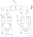
- Fig.1 is a block diagram of an ADSL modem system that may be used in connection with the present invention.
- the system comprises a customer premises modem (ATU-R) 101, a central office modem (ATU-C) 111, and a channel 109 that communicatively couples the modems 101 and 111.
- the modem 101 comprises a transmitter 105, a receiver 103 and a manager 106.
- the manager 106 may comprise, for example, a microprocessor.
- the modem 101 is communicatively coupled to the channel 109 via communication links 107 and 108.
- modem 111 comprises a transmitter 115, a receiver 114 and a manager 118.
- the manager 118 similarly may comprise, for example, a microprocessor.
- the modem 111 is likewise communicatively coupled to the channel 109 via communication links 112 and 113.
- the customer premises modem (ATU-R) 101 estimates the maximum receive data rate. More specifically, for example, the receiver 103, via control path 104, informs the manager 106 about the training signal received. The manager 106 of the customer premises modem (ATU-R) 101 then estimates the maximum rate at which the central office modem (ATU-C) 111 can reliably transmit data to the customer premises modem (ATU-R) 101. The manager 106 compares this maximum receive data rate to a threshold, TR (for example). Depending upon the result of that comparison the manager 106 instructs the transmitter 105 via control path 102 to transmit a command, CR (for example), to the central office modem (ATU-C) 111.
- TR for example
- Command CR may have one of four possible values corresponding to whether the number of bits per symbol transmitted by the central office modem (ATU-C) 111 during SHOWTIME should be a multiple of 8, 4, 2, or 1.
- Command CR may be, for example, encoded by circuits and processes in the transmitter 105, which generates a corresponding signal, SR (for example), that is transmitted to the channel 109 via the communication link 107.
- Signal SR is further conveyed to the receiver 114 of the central office modem (ATU-C) 111 via the connection 113.
- the receiver 114 processes the received signal SR, decodes command CR and transfers it to the manager 115 via control path 116.
- the manager 118 then configures the transmitter 115 to transmit a number of bits per symbol during SHOWTIME that is a multiple of 8, 4, 2, or 1, depending upon the value of command CR.
- the central office modem (ATU-C) 111 estimates the maximum receiver data rate.
- the manager 118 of the central office modem (ATU-C) 111 analyzes the training signal received by the receiver 114 via the control path 116 and estimates the maximum rate at which the customer premises modem (ATU-R) 101 can reliably transmit data to the central office modem (ATU-C) 111.
- the manager 118 compares this maximum receive data rate to a threshold, TC.
- the manager 118 instructs the transmitter 115 via control path 117 to transmit a command, CC (for example), to the customer premises modem (ATU-R) 101.
- CC for example
- Command CC may have one of four possible values corresponding to whether the number of bits per symbol transmitted by the customer premises modem (ATU-R) 101 during SHOWTIME should be a multiple of 8, 4, 2, or 1.
- Command CC may be, for example, encoded by circuits and processes in the transmitter 115, which generates a corresponding signal SC (for example) that is transmitted to the channel 109 via communication link 112.
- Signal SC is further conveyed to the receiver 103 of the customer premises modem (ATU-R) 101 via the communication link 108.
- the receiver 103 processes the received signal SC, decodes command CC and transfers it to the manager 106 via control path 104.
- the manager 106 then configures the transmitter 105 to transmit a number of bits per symbol during SHOWTIME that is a multiple of 8, 4, 2, or 1, depending upon the value of the command, CC.
- Fig. 2 illustrates additional detail of one embodiment of the ADSL modem system of Fig. 1.
- the embodiment of Fig. 2 comprises a customer premises modem (ATU-R) 201, a central office modem (ATU-C) 211, and a channel 221 communicatively coupling the modems 201 and 211.
- the customer premises modem (ATU-R) 201 and the central office modem (ATU-C) 211 contain entities ATU-R manager 203 and ATU-C manager 213, respectively. These managers correspond, respectively, to manager 106 and manager 118 in Fig. 1.
- Fig. 2 illustrates that, while there is no direct connection between ATU-R manager 203 and ATU-C manager 213, a virtual connection exists via paths 209 and 219.
- path 209 is implemented in the form of commands that originate in the customer premises modem (ATU-R) 201 manager 203 in the form of data bits and are communicated to ATU-R PMS-TC (Physical Media-Specific-Transmit Convergence) layer 205 of the customer premises modem (ATU-R) 201.
- the commands pass to ATU-R PMD (Physical Medial-Dependent) layer 207 of the customer premises modem (ATU-R) 201, where they are converted to electrical signals.
- Those signals pass through channel 221 to the ATU-C PMD layer 217 of the central office modem (ATU-C) 211, where they are converted back to data bits. They then pass to ATU-C PMS-TC layer 915 of the central office modem (ATU-C) 211 and then to the ATU-C manager 213.
- Fig. 3 illustrates one embodiment of a PMS-TC Layer architecture that may be used in connection with the present invention.
- Fig. 1 shows some detail regarding PMS-TC Layer 301, which lies above PMD symbol layer 303 and below higher layers 305.
- the ATU-C transmitter i.e., central office modem transmitter
- the remote ATU-R receiver i.e., customer premises modem receiver
- Fig. 4 illustrates one embodiment of the present invention where a multiple of 8 is selected under certain conditions. More specifically, during initialization, the data rate is being estimated, and the ATU-C transmitter obtains information regarding the data rate (block 401). If it is determined that the data rate is high, (i.e., above a certain threshold ⁇ block 403), the transmitter transmits symbols using a multiple of 8 number of bits per symbol (block 405). If, however the data rate is determined to be low (i.e., below the threshold - block 403), the transmitter transmits symbols using an integer number of bits per symbol (block 407). For an 8n system such as shown in Fig. 4, the threshold used may be, for example, 1 Mbits per second, and can be manufacturer specific. The determination at block 403 may be made by, for example, the transmitter itself, or alternatively by the remote receiver. Of course, the same procedure may be used in the opposite direction, but in such case, the threshold would be different (e.g., 250 Kbits per second).
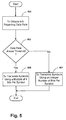
- Fig. 5 illustrates another embodiment of the present invention where a multiple of 4 is selected, rather than a multiple of 8. More specifically, during initialization, the data rate is being estimated, and the ATU-C transmitter obtains information regarding the data rate (block 501). If it is determined that the data rate is high, (i.e., above a certain threshold ⁇ block 503), the transmitter transmits symbols using a multiple of 4 number of bits per symbol (block 505). If, however the data rate is determined to be low (i.e., below the threshold - block 503), the transmitter transmits symbols using an integer number of bits per symbol (block 507). For a 4n system such as shown in Fig. 5, the threshold used may be different than that of Fig. 4, such as, for example, 2 Mbits per second. Of course, the same procedure may be used in the opposite direction, but in such case, the threshold would be different (e.g., 500 Kbits per second).
- Figure 6 illustrates a further embodiment where a multiple of 2 is selected, rather than a multiple of 4 or 8. More specifically, during initialization, the data rate is being estimated, and the ATU-C transmitter obtains information regarding the data rate (block 601). If it is determined that the data rate is high, (i.e., above a certain threshold ⁇ block 603), the transmitter transmits symbols using a multiple of 2 number of bits per symbol (block 605). If, however the data rate is determined to be low (i.e., below the threshold - block 603), the transmitter transmits symbols using an integer number of bits per symbol (block 607). For a 2n system such as shown in Fig. 6, the threshold used may be different than that of either Figs. 4 or 5, such as, for example, 3 Mbits per second. Of course, the same procedure may be used in the opposite direction, but in such case, the threshold would be different (e.g., 750 Kbits per second).
- each of these embodiments is similar in all respects to that discussed above with respect to Fig. 4, except that a different number multiple is transmitted if the estimated data rate is determined to be above the threshold.
- the threshold chosen can again be manufacturer specific.
- Fig. 7 illustrates additional detail regarding one embodiment of the invention discussed above with respect to Fig. 4.
- the transmitter receives information from the remote receiver regarding the estimated data rate (block 701).
- a determination is then made whether the data rate is above a threshold (block 703).
- the threshold may again be, for example, approximately 1 Mbits per second (or alternatively approximately 250 Kbits per second), as discussed above.
- this determination may again be made by the transmitter itself or by the remote receiver, as mentioned above.
- the transmitter sends a message to the remote receiver to choose a symbol size that is a multiple of 8 (block 705).
- This message may simply be in the form of a logical "01,” for example.
- the transmitter sends a message to the remote receiver without restriction to the size of the symbol (block 707).
- This latter message may simply be in the form of a logical "00,” for example.
- the transmitter does not force the remote receiver to choose a multiple of 8 number of bits per symbol, and thus the remote receiver is permitted to use any integer number of bits per symbol.
- Fig. 8 illustrates another embodiment of the present invention where the transmitter sends a message to the remote receiver to choose a symbol size that is a multiple of 4, rather than a multiple of 8.
- the transmitter receives information from the remote receiver regarding the estimated data rate (block 801).
- a determination is then made whether the data rate is above a threshold (block 803).
- the threshold may again be, for example, 2 Mbits per second (or alternatively approximately 500 Kbits per second), as discussed above.
- this determination may again be made by the transmitter itself or by the remote receiver, as mentioned above.
- the transmitter sends a message to the remote receiver to choose a symbol size that is a multiple of 4 (block 805). This message may simply be in the form of a logical "10,” for example.
- the transmitter sends a message to the remote receiver without restriction to the size of the symbol (block 807). Again, this latter message may simply be in the form of a logical "00,” for example.
- the transmitter does not force the remote receiver to choose a multiple of 4 number of bits per symbol, and thus the remote receiver is permitted to use any integer number of bits per symbol.
- Figure 9 illustrates a further embodiment of the present invention where the transmitter sends a message to the remote receiver to choose a symbol size that is a multiple of 2, rather than a multiple of 8 or 4.
- the transmitter receives information from the remote receiver regarding the estimated data rate (block 801).
- a determination is then made whether the data rate is above a threshold (block 803).
- the threshold may again be, for example, 3 Mbits per second (or alternatively approximately 750 Kbits per second), as discussed above.
- this determination may again be made by the transmitter itself or by the remote receiver, as mentioned above.
- the transmitter sends a message to the remote receiver to choose a symbol size that is a multiple of 2 (block 905).
- This message may simply be in the form of a logical "11,” for example.
- the transmitter sends a message to the remote receiver without restriction to the size of the symbol (block 907).
- this latter message may simply be in the form of a logical "00,” for example.
- the transmitter does not force the remote receiver to choose a multiple of 2 number of bits per symbol, and thus the remote receiver is permitted to use any integer number of bits per symbol.
- Figs. 8 and 9 are similar in all respects to that discussed above with respect to Fig. 7, except that a message to choose a different symbol size is sent if the estimated data rate is determined to be above the threshold.
- different thresholds may be used for a 4n or 2n system, as discussed above, and the threshold used can again be manufacturer specific.
- a command is defined and used during initialization to enable an ADSL transmitter to instruct its remote receiver counterpart to ask for byte-oriented processing.
- the transmitter makes this decision based on, for example, details of the manufacturer's implementation and on the estimate of line speed achievable during the connection session.
- Employing the invention permits a manufacturer to trade the dollar cost of implementing high-speed bit-oriented data transmission against a reduction in wasted channel capacity.
- the worst-case wasted capacity is constant (28000 bit/s in the straightforward example). This reduction represents a small percentage of high speeds and a large percentage of low speeds.
- the boundary between "high” and “low” may be manufacturer-dependent. Intelligent use of the invention calls for requesting byte-oriented processing at high speeds, where efficiency is important. At low speeds, again depending upon a manufacturer's implementation, extra signal processing resources may be available to perform the necessary bit-oriented processing, so the request for byte-oriented processing is not necessary.
- a threshold is defined, above which one is willing to pay the speed penalty and below which one has sufficient reserve processing capability to do the required bit-oriented processing in order to avoid the speed penalty.
Landscapes
- Engineering & Computer Science (AREA)
- Signal Processing (AREA)
- Computer Networks & Wireless Communication (AREA)
- Quality & Reliability (AREA)
- Physics & Mathematics (AREA)
- Mathematical Physics (AREA)
- Communication Control (AREA)
- Telephonic Communication Services (AREA)
- Maintenance And Management Of Digital Transmission (AREA)
Applications Claiming Priority (5)
| Application Number | Priority Date | Filing Date | Title |
|---|---|---|---|
| US882100 | 1986-07-03 | ||
| US29223001P | 2001-05-18 | 2001-05-18 | |
| US292230 | 2001-05-18 | ||
| US292230P | 2001-05-18 | ||
| US09/882,100 US20020172274A1 (en) | 2001-05-18 | 2001-06-15 | Method of intelligently restricting symbol size in ADSL modems |
Publications (3)
| Publication Number | Publication Date |
|---|---|
| EP1259020A2 true EP1259020A2 (de) | 2002-11-20 |
| EP1259020A3 EP1259020A3 (de) | 2003-11-26 |
| EP1259020B1 EP1259020B1 (de) | 2005-08-10 |
Family
ID=26967224
Family Applications (1)
| Application Number | Title | Priority Date | Filing Date |
|---|---|---|---|
| EP02253320A Expired - Lifetime EP1259020B1 (de) | 2001-05-18 | 2002-05-13 | Verfahren zur Einschränkung der Symbollänge für ADSL-modems |
Country Status (3)
| Country | Link |
|---|---|
| US (1) | US20020172274A1 (de) |
| EP (1) | EP1259020B1 (de) |
| DE (1) | DE60205426T2 (de) |
Families Citing this family (6)
| Publication number | Priority date | Publication date | Assignee | Title |
|---|---|---|---|---|
| WO2006128323A1 (fr) * | 2005-06-02 | 2006-12-07 | Zte Corporation | Procede d'implementation du changement de debit des donnees de la couche de convergence de transmission dans un systeme adsl et appareil associe |
| US7920597B2 (en) * | 2007-03-12 | 2011-04-05 | Broadcom Corporation | Method and system for low power idle signal transmission in ethernet networks |
| US7916676B2 (en) * | 2007-03-23 | 2011-03-29 | Broadcom Corporation | Method and system for holistic energy management in ethernet networks |
| US8724464B2 (en) * | 2007-12-17 | 2014-05-13 | Broadcom Corporation | Method and system for near continuous data rate limit adjustment via a plurality of link variables in an energy efficient network |
| US8588254B2 (en) * | 2007-12-17 | 2013-11-19 | Broadcom Corporation | Method and system for energy efficient signaling for 100mbps Ethernet using a subset technique |
| US8565269B2 (en) | 2008-04-15 | 2013-10-22 | Broadcom Corporation | Method and system for MAC and PHY synchronization for energy efficient networking |
Family Cites Families (13)
| Publication number | Priority date | Publication date | Assignee | Title |
|---|---|---|---|---|
| US5781598A (en) * | 1996-08-14 | 1998-07-14 | Hardy, Iii; Harmon S. | System and method of asynchronous data transfer through a plurality of modems |
| DE19651593B4 (de) * | 1996-12-11 | 2008-11-20 | Rohde & Schwarz Gmbh & Co. Kg | Anordnung zum Optimieren der Datenübertragung über einen bidirektionalen Funkkanal |
| US6061392A (en) * | 1996-12-17 | 2000-05-09 | Paradyne Corporation | Apparatus and method for communicating voice and data between a customer premises and a central office |
| US6137829A (en) * | 1997-03-05 | 2000-10-24 | Paradyne Corporation | System and method for transmitting special marker symbols |
| US6266348B1 (en) * | 1997-10-10 | 2001-07-24 | Aware, Inc. | Splitterless multicarrier modem |
| CA2240596A1 (en) * | 1997-11-28 | 1999-05-28 | Newbridge Networks Corporation | Controlling atm layer transfer characteristics based on physical layer dynamic rate adaptation |
| US5999540A (en) * | 1998-12-22 | 1999-12-07 | Cisco Technology, Inc. | Rate adaptive XDSL communication system and method |
| US6310909B1 (en) * | 1998-12-23 | 2001-10-30 | Broadcom Corporation | DSL rate adaptation |
| HK1040147B (en) * | 1999-03-12 | 2006-07-21 | Daphimo Co. B.V., Llc | Seamless rate adaptive multicarrier modulation system and protocols |
| US6532267B1 (en) * | 1999-05-21 | 2003-03-11 | Alantro Communications, Inc. | Variable rate constellation precoding |
| EP1087586A3 (de) * | 1999-09-24 | 2005-06-08 | PC-Tel, Inc. | Verfahren zur Datenzuweisung für Mehrträgerübertragung |
| US6980601B2 (en) * | 2000-11-17 | 2005-12-27 | Broadcom Corporation | Rate adaptation and parameter optimization for multi-band single carrier transmission |
| US7031345B1 (en) * | 2000-12-21 | 2006-04-18 | Cisco Technology, Inc. | Method and system for rate adaptive ISDN communication |
-
2001
- 2001-06-15 US US09/882,100 patent/US20020172274A1/en not_active Abandoned
-
2002
- 2002-05-13 EP EP02253320A patent/EP1259020B1/de not_active Expired - Lifetime
- 2002-05-13 DE DE60205426T patent/DE60205426T2/de not_active Expired - Lifetime
Also Published As
| Publication number | Publication date |
|---|---|
| DE60205426D1 (de) | 2005-09-15 |
| US20020172274A1 (en) | 2002-11-21 |
| EP1259020A3 (de) | 2003-11-26 |
| DE60205426T2 (de) | 2006-06-08 |
| EP1259020B1 (de) | 2005-08-10 |
Similar Documents
| Publication | Publication Date | Title |
|---|---|---|
| US8385237B2 (en) | Method and system for simplex or duplex transmission mode of an ethernet link in an energy efficient network | |
| US6229818B1 (en) | Active isolation system and method for allowing local and remote data transfers across a common data link | |
| US20090154455A1 (en) | Method And System For Near Continuous Data Rate Limit Adjustment Via A Plurality Of Link Variables In An Energy Efficient Network | |
| EP1079578A2 (de) | Datenzuweisung in Mehrträgersystemen | |
| AU751233B2 (en) | Parallel backplane physical layer interface with scalable data bandwidth | |
| US20090316718A1 (en) | Multi-Port Ethernet Transceiver | |
| US20110019725A1 (en) | Dsl method having variable upload/download bit rate and application-specific dynamic profile switching | |
| CN101610191A (zh) | 多模式以太网收发信机 | |
| US6542581B2 (en) | Method for controlling the transmission power in a digital subscriber line | |
| US10148508B1 (en) | Method and system for ethernet transceiver rate control | |
| EP1259020B1 (de) | Verfahren zur Einschränkung der Symbollänge für ADSL-modems | |
| US8208520B2 (en) | Variable state length initialization | |
| US6922415B1 (en) | Apparatus and method for a non-symmetrical half-duplex DSL modem | |
| US8971390B2 (en) | Power saving in a communication device | |
| US8009726B2 (en) | Carrier grouping in multi-carrier systems | |
| US5369636A (en) | Multiple communication speed converting apparatus | |
| KR100269148B1 (ko) | 전화회선을이용한전화및데이터통신장치 | |
| US20020054631A1 (en) | Modem and method for adjusting data transmission speed of the same | |
| EP1540871B1 (de) | Verfahren und anordnung zur einstellung der sendeleistung in einer digitalen teilnehmerleitung | |
| US20020141553A1 (en) | Transmission line rerouting method, subscriber line accommodating apparatus and trunk transmission line accommodating apparatus | |
| US7075976B1 (en) | Tri-state transmitter | |
| EP0983691A2 (de) | Vorrichtung und verfahren für ein dsl-mehrpunktmodem | |
| US20030118091A1 (en) | System and method for reducing power dissipation for DSL circuits | |
| US20030007506A1 (en) | Aggregate throughput control in a modem pool environment | |
| KR20030055567A (ko) | 엑스디에스엘시스템의 핸드쉐이킹 제어방법 |
Legal Events
| Date | Code | Title | Description |
|---|---|---|---|
| PUAI | Public reference made under article 153(3) epc to a published international application that has entered the european phase |
Free format text: ORIGINAL CODE: 0009012 |
|
| AK | Designated contracting states |
Kind code of ref document: A2 Designated state(s): AT BE CH CY DE DK ES FI FR GB GR IE IT LI LU MC NL PT SE TR |
|
| AX | Request for extension of the european patent |
Free format text: AL;LT;LV;MK;RO;SI |
|
| PUAL | Search report despatched |
Free format text: ORIGINAL CODE: 0009013 |
|
| AK | Designated contracting states |
Kind code of ref document: A3 Designated state(s): AT BE CH CY DE DK ES FI FR GB GR IE IT LI LU MC NL PT SE TR |
|
| AX | Request for extension of the european patent |
Extension state: AL LT LV MK RO SI |
|
| 17P | Request for examination filed |
Effective date: 20040526 |
|
| AKX | Designation fees paid |
Designated state(s): DE FR GB |
|
| 17Q | First examination report despatched |
Effective date: 20040802 |
|
| GRAP | Despatch of communication of intention to grant a patent |
Free format text: ORIGINAL CODE: EPIDOSNIGR1 |
|
| GRAS | Grant fee paid |
Free format text: ORIGINAL CODE: EPIDOSNIGR3 |
|
| GRAA | (expected) grant |
Free format text: ORIGINAL CODE: 0009210 |
|
| AK | Designated contracting states |
Kind code of ref document: B1 Designated state(s): DE FR GB |
|
| REG | Reference to a national code |
Ref country code: GB Ref legal event code: FG4D |
|
| REF | Corresponds to: |
Ref document number: 60205426 Country of ref document: DE Date of ref document: 20050915 Kind code of ref document: P |
|
| ET | Fr: translation filed | ||
| PLBE | No opposition filed within time limit |
Free format text: ORIGINAL CODE: 0009261 |
|
| STAA | Information on the status of an ep patent application or granted ep patent |
Free format text: STATUS: NO OPPOSITION FILED WITHIN TIME LIMIT |
|
| 26N | No opposition filed |
Effective date: 20060511 |
|
| REG | Reference to a national code |
Ref country code: FR Ref legal event code: CA |
|
| PGFP | Annual fee paid to national office [announced via postgrant information from national office to epo] |
Ref country code: GB Payment date: 20130522 Year of fee payment: 12 |
|
| PGFP | Annual fee paid to national office [announced via postgrant information from national office to epo] |
Ref country code: FR Payment date: 20130604 Year of fee payment: 12 |
|
| PGFP | Annual fee paid to national office [announced via postgrant information from national office to epo] |
Ref country code: DE Payment date: 20140531 Year of fee payment: 13 |
|
| REG | Reference to a national code |
Ref country code: DE Ref legal event code: R119 Ref document number: 60205426 Country of ref document: DE |
|
| GBPC | Gb: european patent ceased through non-payment of renewal fee |
Effective date: 20140513 |
|
| REG | Reference to a national code |
Ref country code: FR Ref legal event code: ST Effective date: 20150130 |
|
| PG25 | Lapsed in a contracting state [announced via postgrant information from national office to epo] |
Ref country code: FR Free format text: LAPSE BECAUSE OF NON-PAYMENT OF DUE FEES Effective date: 20140602 Ref country code: GB Free format text: LAPSE BECAUSE OF NON-PAYMENT OF DUE FEES Effective date: 20140513 |
|
| PG25 | Lapsed in a contracting state [announced via postgrant information from national office to epo] |
Ref country code: DE Free format text: LAPSE BECAUSE OF NON-PAYMENT OF DUE FEES Effective date: 20141202 |