EP1259013A1 - Device and method for displaying code domain power - Google Patents
Device and method for displaying code domain power Download PDFInfo
- Publication number
- EP1259013A1 EP1259013A1 EP00985927A EP00985927A EP1259013A1 EP 1259013 A1 EP1259013 A1 EP 1259013A1 EP 00985927 A EP00985927 A EP 00985927A EP 00985927 A EP00985927 A EP 00985927A EP 1259013 A1 EP1259013 A1 EP 1259013A1
- Authority
- EP
- European Patent Office
- Prior art keywords
- signal
- digital
- signals
- code domain
- display
- Prior art date
- Legal status (The legal status is an assumption and is not a legal conclusion. Google has not performed a legal analysis and makes no representation as to the accuracy of the status listed.)
- Granted
Links
- 238000000034 method Methods 0.000 title claims abstract description 31
- 210000001233 cdp Anatomy 0.000 claims abstract description 19
- 238000004637 computerized dynamic posturography Methods 0.000 claims abstract description 19
- 239000003086 colorant Substances 0.000 claims description 5
- 230000004044 response Effects 0.000 claims description 3
- 238000010586 diagram Methods 0.000 abstract description 18
- 230000008569 process Effects 0.000 abstract description 16
- 210000004027 cell Anatomy 0.000 description 3
- 238000011144 upstream manufacturing Methods 0.000 description 3
- 230000010363 phase shift Effects 0.000 description 2
- 230000008901 benefit Effects 0.000 description 1
- 230000007257 malfunction Effects 0.000 description 1
- 238000010295 mobile communication Methods 0.000 description 1
- 230000007480 spreading Effects 0.000 description 1
Images



Classifications
-
- H—ELECTRICITY
- H04—ELECTRIC COMMUNICATION TECHNIQUE
- H04B—TRANSMISSION
- H04B1/00—Details of transmission systems, not covered by a single one of groups H04B3/00 - H04B13/00; Details of transmission systems not characterised by the medium used for transmission
- H04B1/69—Spread spectrum techniques
- H04B1/707—Spread spectrum techniques using direct sequence modulation
-
- H—ELECTRICITY
- H04—ELECTRIC COMMUNICATION TECHNIQUE
- H04L—TRANSMISSION OF DIGITAL INFORMATION, e.g. TELEGRAPHIC COMMUNICATION
- H04L1/00—Arrangements for detecting or preventing errors in the information received
- H04L1/24—Testing correct operation
Definitions
- the present invention relates to an apparatus for testing a mobile communication system. More particularly, the present invention relates to an apparatus and a method for displaying code domain power in a code domain measuring apparatus.
- CDMA Code Division Multiple Access
- TM Code Division Multiple Access
- the code domain measuring apparatus For measuring the code domain power (CDP) of a CDMA (Code Division Multiple Access) signal such as of cdmaOne(TM) or the like with a conventional code domain measuring apparatus, it has been customary for the code domain measuring apparatus to employ a process of displaying codes on a horizontal axis and the power of the codes on a vertical axis, as shown in FIG. 1 of the accompanying drawings.
- Japanese patent application No. 11-125658 entitled “Method of displaying the power level of CDMA signal” on May 6, 1999.
- the Japanese patent application discloses a technique for indicating in which code layer each active code channel is active and allowing the observer to observe the power level easily, using the width of the bars shown in FIG. 1.
- FIG. 2 is a block diagram of a conventional code domain power analyzing apparatus 20
- FIG. 3 is a detailed block diagram of a digital processor 24 which is part of the code domain power analyzing apparatus 20.
- An intermediate frequency (IF) signal is generated from an input CDMA signal (RF signal) by a down converter 21 and a low-pass filter 22.
- the IF signal is input to an analog-to-digital converter (A/D converter) 23, which inputs a digital IF signal to a digital processor 24.
- A/D converter analog-to-digital converter
- the digital processor 24 comprises an IQ demodulator 31, filters 32, a descrambler/despreading means 33, and a code domain power (CDP) calculator 34.
- the digital IF signal is divided by the IQ demodulator 31 into an in-phase (I) component signal and a quadrature (Q) component signal, which are supplied through the respective filters 32 as QPSK modulated signals containing amplitude and phase information to the descrambling/despreading means 33, respectively.
- the descrambler/despreading means 33 descrambles and despreads the two component signals as the QPSK modulated signals.
- the CDP calculator 34 calculates CDP from an output signal from the descrambling/despreading means 33, and generates a signal for displaying the bars as shown in FIG. 1 on a display unit 25.
- the Japanese patent application also discloses a process of displaying the bars in different colors to distinguish the power of an active code channel from the power of inactive code channels.
- the disclosed process makes it possible to allow the observer to observe the power of a plurality of code layers at the same time, unlike the conventional process which has allowed the observer to observe the code power of only one code layer per screen on the measuring unit.
- HPSK Hybrid Phase Shift Keying
- OCQPSK Orthogonal Complex Quadrature Phase Shift Keying
- an apparatus for displaying code domain power is arranged as follows:
- the apparatus has a down-converter for receiving a CDMA signal and down-converting the CDMA signal into an intermediate frequency (IF) signal, a analog-to-digital (A/D) converter for converting the generated IF signal into a digital IF signal, a digital signal processor for demodulating the digital IF signal into I and Q components, descrambling and despreading the I and Q components to calculate code domain power (CDP), and display for displaying the CDP in response to signals from the digital signal processor, wherein the digital signal processor descrambles and despreads I and Q component signals having amplitude and phase information obtained by demodulating the digital IF signal, individually as BPSK modulated signals, calculates CDPs with respect to I- and Q-axes from two different signals calculated by descrambling and despreading the I and Q component signals, and has the display show the CDPs of each of the I- and Q-axes
- the digital signal processor may descramble and despread I and Q component signals having amplitude and phase information obtained by demodulating the digital IF signal, as QPSK modulated signals with a first scrambling code, and simultaneously descramble and despread the I and Q component signals as QPSK modulated signals with a second scrambling code, calculate CDPs with respect to I- and Q-axes from two different signals obtained by descrambling and despreading the I and Q component signals with the scrambling codes, and display the CDPs corresponding to the first and second scrambling codes distinguishably on the display.
- the code domain powers with respect a downstream signal scrambled with different scrambling codes can be simultaneously displayed for the respective scrambling codes. Since the scrambling codes are assigned to respective cells or sectors, the code domain power between sectors or cells can simply be observed advantageously.
- the digital signal processor may be arranged to enable the display to display the CDPs calculated from the two different signals calculated by descrambling and despreading the I and Q components, on respective different axes of dimension.
- the power distributed on the I- and Q-axes and the relationship between the power and codes can quickly be recognized visually.
- the arrangement is also highly advantageous in that it can not only determine whether an upstream signal modulator is normal or not, but also can easily obtain information necessary to analyze the cause of a malfunction.
- For displaying the CDP of a downstream signal scrambled with different scrambling codes since the powers are displayed on different axes of dimension for respective codes, the powers can be simultaneously displayed and the power distribution can quickly be recognized visually.
- the digital signal processor may be arranged to enable the display to display the CDPs calculated from the two different signals calculated by descrambling and despreading the I and Q components, on an identical axis of dimension in a stacked fashion.
- the total power for the same code that is distributed on the I-axis and the Q-axis can easilybe observed. This function is particularly effective in confirming the power distribution for the codes as required in an initial phase of development of terminals.
- the digital signal processor may be arranged to enable the display to display the CDPs in a visually distinguishable manner with colors or patterns, said CDPs have been calculated from the two different signals calculated by descrambling and despreading the I and Q components.
- the power at a desired code and the power distributed on the I- and Q-axes can be distinguished from each other.
- FIG. 4 a method of displaying code domain power (hereinafter referred to as CDP) according to the present invention for achieving the above object simultaneously displays the power of the I-axis and the power of the Q-axis as bars above and below a horizontal axis (codes) (e.g., the power of the I-axis above the horizontal axis and the power of the Q-axis below the horizontal axis), with each of the bars having a length representing the power level and a width representing a code layer where an active channel locates.
- FIG. 5 is a block diagram of a code domain power analyzing apparatus 50 according to the present invention for carrying out the above method, and FIG.
- FIG. 6 is a detailed block diagram of a digital processor 54 which is part of the code domain power analyzing apparatus 50.
- the block diagram of the CDP analyzing apparatus 50 is the same as the block diagram of the conventional CDP analyzing apparatus 20, but differs essentially therefrom in that the digital processor 54 descrambles and despreads an I component and a Q component as BPSK modulated signals separately from each other as shown in FIG. 6.
- a sequence of operation of the CDP analyzing apparatus 50 according to the present invention will be described below.
- a received CDMA signal (RF signal) is downconverted into an intermediate frequency (IF) signal by a down converter 21 and a low-pass filter 22.
- the IF signal is input to an analog-to-digital converter (A/D converter) 23, which inputs a digital IF signal to the digital processor 54.
- the digital processor 54 comprises an IQ demodulator 31, filters 32, descrambler/despreading means 63, and code domain power (CDP) calculators 64.
- the digital IF signal is divided into an in-phase (I) component signal and a quadrature (Q) component signal, which are supplied through the respective filters 32 as BPSK modulated signals containing amplitude and phase information individually to the respective descrambler/despreading means 63.
- the descrambler/despreading means 63 individually descramble and despread the two component signals respectively as the BPSK modulated signals.
- a signal obtained from the I component signal is input to one of the CDP calculator 34, which calculates CDP of the I-axis.
- a signal obtained from the Q component signal is input to the other CDP calculator 34, which calculates CDP of the Q-axis.
- These CDP calculator 34 generate signals for displaying the bars as shown in FIG. 4 on a display unit 25.
- FIG. 7 shows a CDP analyzing apparatus 70 according to a second embodiment of the present invention, for displaying the power of code domains of different scrambling codes for a downstream signal.
- FIG. 8 is a detailed block diagram of a digital processor 74 which is part of the code domain power analyzing apparatus 70.
- the CDP analyzing apparatus 70 is capable of simultaneously displaying two types of signals of different scrambling codes (signals scrambled respectively by a first scrambling code and a second scrambling code) respectively above and below a code axis.
- the signals thus displayed make it possible to easily observe leakages of code domain power across sectors or cells.
- the arrangement shown in FIGS. 7 and 8 has been devised to carry out such a displaying process.
- the CDP displaying apparatus is the same as the CDP displaying apparatus according to the first embodiment except for the digital signal processor 74.
- the second embodiment is also characterized by the digital signal processor 74.
- a digital IF signal generated by the A/D converter 23 is IQ-demodulated into two signals containing amplitude and phase information.
- the two signals as QPSK modulated signals are descrambled and despread (by a first descrambler/despreading means 83) with a first scrambling code, and are simultaneously descrambled and despread (by a second descrambler/despreading means 84) with a second scrambling code.
- the two signals thus descrambled and despread with the respective two scrambling codes are processed to calculate CDP by the respective CDP calculators 64 for displaying the CDP above and below the code axis.
- the CDP calculators 64 generate signals for displaying the bars as shown in FIG. 4 on the display unit 25.
- the bars are of the same type as described above, but the power of the I-axis and the power of the Q-axis are displayed in a stacked fashion.
- This display mode is suitable for observing the total power for the same code that is distributed on the I-axis and the Q-axis.
- the display mode is also effective in confirming the power distribution for the codes because the power distribution is required in an initial phase of development of terminals.
- the display mode can be achieved by modifying the program in a stage for performing the CDP calculation by the digital signal processor 54 and 74.
- the power distributed on the I-axis and the Q-axis may be expressed so as to be identified visually with some attributes (e.g., colors or patterns) of the bars that indicate the power, so that the power of a desired code and the power due to an error can be distinguished from each other.
- This method is particularly effective because it allows the power distributed on the axes can easily be identified, according to the third embodiment, and because it allows the total power for the same code that is distributed on the I-axis and the Q-axis to be easily observed.
- This process can also be achieved by modifying the program of the digital signal processor.
Landscapes
- Engineering & Computer Science (AREA)
- Computer Networks & Wireless Communication (AREA)
- Signal Processing (AREA)
- Mobile Radio Communication Systems (AREA)
- Digital Transmission Methods That Use Modulated Carrier Waves (AREA)
Abstract
Description
- The present invention relates to an apparatus for testing a mobile communication system. More particularly, the present invention relates to an apparatus and a method for displaying code domain power in a code domain measuring apparatus.
- For measuring the code domain power (CDP) of a CDMA (Code Division Multiple Access) signal such as of cdmaOne(TM) or the like with a conventional code domain measuring apparatus, it has been customary for the code domain measuring apparatus to employ a process of displaying codes on a horizontal axis and the power of the codes on a vertical axis, as shown in FIG. 1 of the accompanying drawings.
- The applicant (assignee) of the present application has filed Japanese patent application No. 11-125658 entitled "Method of displaying the power level of CDMA signal" on May 6, 1999. In the disclosed method, there has been described a process of displaying the power levels in respective active code channels in a plurality of code layers with bars shown in FIG. 1. The Japanese patent application discloses a technique for indicating in which code layer each active code channel is active and allowing the observer to observe the power level easily, using the width of the bars shown in FIG. 1.
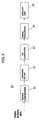
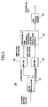
- One apparatus for carrying out such a process of code domain power is shown in FIGS. 2 and 3 of the accompanying drawings. FIG. 2 is a block diagram of a conventional code domain
power analyzing apparatus 20, and FIG. 3 is a detailed block diagram of adigital processor 24 which is part of the code domainpower analyzing apparatus 20. An intermediate frequency (IF) signal is generated from an input CDMA signal (RF signal) by adown converter 21 and a low-pass filter 22. The IF signal is input to an analog-to-digital converter (A/D converter) 23, which inputs a digital IF signal to adigital processor 24. As shown in FIG. 3, thedigital processor 24 comprises anIQ demodulator 31,filters 32, a descrambler/despreading means 33, and a code domain power (CDP)calculator 34. The digital IF signal is divided by theIQ demodulator 31 into an in-phase (I) component signal and a quadrature (Q) component signal, which are supplied through therespective filters 32 as QPSK modulated signals containing amplitude and phase information to the descrambling/despreading means 33, respectively. The descrambler/despreading means 33 descrambles and despreads the two component signals as the QPSK modulated signals. TheCDP calculator 34 calculates CDP from an output signal from the descrambling/despreading means 33, and generates a signal for displaying the bars as shown in FIG. 1 on adisplay unit 25. - The Japanese patent application also discloses a process of displaying the bars in different colors to distinguish the power of an active code channel from the power of inactive code channels. The disclosed process makes it possible to allow the observer to observe the power of a plurality of code layers at the same time, unlike the conventional process which has allowed the observer to observe the code power of only one code layer per screen on the measuring unit.
- There has in recent years been proposed a modulating process referred to as HPSK (Hybrid Phase Shift Keying) (also known as OCQPSK (Orthogonal Complex Quadrature Phase Shift Keying) as a spreading process for use in W-CDMA and cdma2000 which are new standards to be introduced in the future, for the purpose of increasing the frequency utilization efficiency of upstream signals from terminal devices to base stations. The proposed modulating process is a process of carrying different items of information on I- and Q-axes of the constellation (signal dot diagram). For measuring an upstream CDMA signal according to the modulating process, it is necessary to take into account another different dimension in addition to codes on the code domain. The power of codes and leakages of the power to other codes, not only in one axis, but also from the I-axis to the Q-axis and vice versa, need to be measured and displayed so that they can be read accurately and quickly. However, it is impossible for the conventional CDP displaying process shown in FIG. 1 and the conventional apparatus shown in FIGS. 2 and 3 to display the power of the I-axis and the power of the Q-axis distinguishably from each other.
- It is an object of the present invention to provide a novel method of displaying code domain power and a novel apparatus for measuring code domain power, which are suitable for analyzing a CDMA signal according to an HPSK modulating process.
- To achieve the above object, an apparatus for displaying code domain power according to the present invention is arranged as follows: The apparatus has a down-converter for receiving a CDMA signal and down-converting the CDMA signal into an intermediate frequency (IF) signal, a analog-to-digital (A/D) converter for converting the generated IF signal into a digital IF signal, a digital signal processor for demodulating the digital IF signal into I and Q components, descrambling and despreading the I and Q components to calculate code domain power (CDP), and display for displaying the CDP in response to signals from the digital signal processor, wherein the digital signal processor descrambles and despreads I and Q component signals having amplitude and phase information obtained by demodulating the digital IF signal, individually as BPSK modulated signals, calculates CDPs with respect to I- and Q-axes from two different signals calculated by descrambling and despreading the I and Q component signals, and has the display show the CDPs of each of the I- and Q-axes distinguishably. Since the I and Q components are individually descrambled and despread, the power distributed on the I- and Q-axes by HPSK can distinguishably be extracted and displayed to the advantage of the observer.
- The digital signal processor may descramble and despread I and Q component signals having amplitude and phase information obtained by demodulating the digital IF signal, as QPSK modulated signals with a first scrambling code, and simultaneously descramble and despread the I and Q component signals as QPSK modulated signals with a second scrambling code, calculate CDPs with respect to I- and Q-axes from two different signals obtained by descrambling and despreading the I and Q component signals with the scrambling codes, and display the CDPs corresponding to the first and second scrambling codes distinguishably on the display. With this arrangement, the code domain powers with respect a downstream signal scrambled with different scrambling codes can be simultaneously displayed for the respective scrambling codes. Since the scrambling codes are assigned to respective cells or sectors, the code domain power between sectors or cells can simply be observed advantageously.
- In addition, the digital signal processor may be arranged to enable the display to display the CDPs calculated from the two different signals calculated by descrambling and despreading the I and Q components, on respective different axes of dimension. With this arrangement, the power distributed on the I- and Q-axes and the relationship between the power and codes can quickly be recognized visually. The arrangement is also highly advantageous in that it can not only determine whether an upstream signal modulator is normal or not, but also can easily obtain information necessary to analyze the cause of a malfunction. For displaying the CDP of a downstream signal scrambled with different scrambling codes, since the powers are displayed on different axes of dimension for respective codes, the powers can be simultaneously displayed and the power distribution can quickly be recognized visually.
- Alternatively, the digital signal processor may be arranged to enable the display to display the CDPs calculated from the two different signals calculated by descrambling and despreading the I and Q components, on an identical axis of dimension in a stacked fashion. With this arrangement, the total power for the same code that is distributed on the I-axis and the Q-axis can easilybe observed. This function is particularly effective in confirming the power distribution for the codes as required in an initial phase of development of terminals.
- Further alternatively, the digital signal processor may be arranged to enable the display to display the CDPs in a visually distinguishable manner with colors or patterns, said CDPs have been calculated from the two different signals calculated by descrambling and despreading the I and Q components. With this arrangement, the power at a desired code and the power distributed on the I- and Q-axes can be distinguished from each other.
-
- FIG. 1 is a diagram showing a conventional manner for displaying CDP;
- FIG. 2 is a block diagram of a conventional
code domain
power analyzing apparatus 20; - FIG. 3 is a detailed block diagram of a
digital processor 24 shown in FIG. 2; - FIG. 4 is a diagram showing a style for displaying CDP according to an embodiment of the present invention;
- FIG. 5 is a block diagram of a code domain
power analyzing apparatus 50 according to the present invention; - FIG. 6 is a detailed block diagram of a
digital processor 54 shown in FIG. 5; - FIG. 7 is a block diagram of a code domain
power analyzing apparatus 70 according to a second embodiment of the present invention; - FIG. 8 is a detailed block diagram of a
digital processor 74 shown in FIG. 7; and - FIG. 9 is a diagram showing a style for displaying CDP according to another embodiment of the present invention.
-
- Embodiments which are considered as best at present will be described in detail below with reference to the drawings. Components denoted by like reference numerals have like functions throughout the figures.
- As shown in FIG. 4, a method of displaying code domain power (hereinafter referred to as CDP) according to the present invention for achieving the above object simultaneously displays the power of the I-axis and the power of the Q-axis as bars above and below a horizontal axis (codes) (e.g., the power of the I-axis above the horizontal axis and the power of the Q-axis below the horizontal axis), with each of the bars having a length representing the power level and a width representing a code layer where an active channel locates. FIG. 5 is a block diagram of a code domain
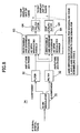
power analyzing apparatus 50 according to the present invention for carrying out the above method, and FIG. 6 is a detailed block diagram of adigital processor 54 which is part of the code domainpower analyzing apparatus 50. Basically, the block diagram of theCDP analyzing apparatus 50 is the same as the block diagram of the conventionalCDP analyzing apparatus 20, but differs essentially therefrom in that thedigital processor 54 descrambles and despreads an I component and a Q component as BPSK modulated signals separately from each other as shown in FIG. 6. A sequence of operation of theCDP analyzing apparatus 50 according to the present invention will be described below. - A received CDMA signal (RF signal) is downconverted into an intermediate frequency (IF) signal by a
down converter 21 and a low-pass filter 22. The IF signal is input to an analog-to-digital converter (A/D converter) 23, which inputs a digital IF signal to thedigital processor 54. As shown in FIG. 6, thedigital processor 54 comprises anIQ demodulator 31,filters 32, descrambler/despreading means 63, and code domain power (CDP)calculators 64. By means of theIQ demodulator 31, the digital IF signal is divided into an in-phase (I) component signal and a quadrature (Q) component signal, which are supplied through therespective filters 32 as BPSK modulated signals containing amplitude and phase information individually to the respective descrambler/despreading means 63. The descrambler/despreading means 63 individually descramble and despread the two component signals respectively as the BPSK modulated signals. A signal obtained from the I component signal is input to one of theCDP calculator 34, which calculates CDP of the I-axis. A signal obtained from the Q component signal is input to theother CDP calculator 34, which calculates CDP of the Q-axis. TheseCDP calculator 34 generate signals for displaying the bars as shown in FIG. 4 on adisplay unit 25. - FIG. 7 shows a
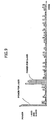
CDP analyzing apparatus 70 according to a second embodiment of the present invention, for displaying the power of code domains of different scrambling codes for a downstream signal. FIG. 8 is a detailed block diagram of adigital processor 74 which is part of the code domainpower analyzing apparatus 70. TheCDP analyzing apparatus 70 is capable of simultaneously displaying two types of signals of different scrambling codes (signals scrambled respectively by a first scrambling code and a second scrambling code) respectively above and below a code axis. The signals thus displayed make it possible to easily observe leakages of code domain power across sectors or cells. The arrangement shown in FIGS. 7 and 8 has been devised to carry out such a displaying process. The CDP displaying apparatus according to the second embodiment is the same as the CDP displaying apparatus according to the first embodiment except for thedigital signal processor 74. The second embodiment is also characterized by thedigital signal processor 74. In thedigital signal processor 74, a digital IF signal generated by the A/D converter 23 is IQ-demodulated into two signals containing amplitude and phase information. The two signals as QPSK modulated signals are descrambled and despread (by a first descrambler/despreading means 83) with a first scrambling code, and are simultaneously descrambled and despread (by a second descrambler/despreading means 84) with a second scrambling code. The two signals thus descrambled and despread with the respective two scrambling codes are processed to calculate CDP by therespective CDP calculators 64 for displaying the CDP above and below the code axis. TheCDP calculators 64 generate signals for displaying the bars as shown in FIG. 4 on thedisplay unit 25. - According to a third embodiment of the present invention, as shown in FIG. 9, the bars are of the same type as described above, but the power of the I-axis and the power of the Q-axis are displayed in a stacked fashion. This display mode is suitable for observing the total power for the same code that is distributed on the I-axis and the Q-axis. The display mode is also effective in confirming the power distribution for the codes because the power distribution is required in an initial phase of development of terminals. The display mode can be achieved by modifying the program in a stage for performing the CDP calculation by the
digital signal processor - The power distributed on the I-axis and the Q-axis may be expressed so as to be identified visually with some attributes (e.g., colors or patterns) of the bars that indicate the power, so that the power of a desired code and the power due to an error can be distinguished from each other. This method is particularly effective because it allows the power distributed on the axes can easily be identified, according to the third embodiment, and because it allows the total power for the same code that is distributed on the I-axis and the Q-axis to be easily observed. This process can also be achieved by modifying the program of the digital signal processor.
- While the most preferred embodiments of the present invention have been described in detail, the above embodiments may be modified or corrected without departing from the spirit of the present invention. The scope of the present invention is limited only by the description in the scope of claims for patent.
Claims (10)
- An apparatus for displaying code domain power in a CDMA signal analysis, comprising:wherein said digital signal processor descrambles and despreads I and Q component signals having amplitude and phase information obtained by demodulating the digital IF signal, individually as BPSK modulated signals, calculates CDPs with respect to I- and Q-axes from two different signals obtained by descrambling and despreading the I and Q component signals, and enables said display to display the calculated CDPs of each of the I- and Q-axes distinguishably.a down-converter for receiving a CDMA signal and down-converting the CDMA signal into an intermediate frequency (IF) signal;an analog-to-digital (A/D) converter for converting the generated IF signal into a digital IF signal;a digital signal processor for IQ-demodulating the digital IF signal, descrambling and despreading I and Q components to calculate code domain power (CDP); anda display for displaying the CDP in response to signals from the digital signal processor;
- An apparatus for displaying code domain power in a CDMA signal analysis, comprising a down-converter for receiving a CDMA signal and down-converting the CDMA signal into an intermediate frequency (IF) signal;
a analog-to-digital (A/D) converter for converting the generated IF signal into a digital IF signal;
a digital signal processor for demodulating the digital IF signal into I and Q components, descrambling and despreading the I and Q components to calculate code domain power (CDP); and
a display for displaying the CDP in response to signals from the digital signal processing means;
wherein said digital signal processor descrambles and despreads I and Q component signals having amplitude and phase information obtained by demodulating the digital IF signal, as QPSK modulated signals with a first scrambling code; simultaneously descrambles and despreads the I and Q component signals as QPSK modulated signals with a second scrambling code; calculates each CDP with respect to I- and Q-axes from two different signals obtained by descrambling and despreading the I and Q component signals with the scrambling codes; and enables the display to display the CDPs corresponding to the first and second scrambling codes distinguishably. - An apparatus according to claim 1, wherein said digital signal processor enables said display to display the CDPs calculated from said two different signals on respective different axes of dimension.
- An apparatus according to claim 1, wherein said digital signal processor enables said display to display the CDPs calculated from said two different signals on an identical axis of dimension in a stacked fashion.
- An apparatus according to claim 1, wherein said digital signal processing means enables said display means to display the CDPs visually distinguishably with colors or patterns, said CDPs are calculated from said two different signals.
- A method of displaying code domain power, comprising: converting a frequency of a CDMA signal to generate an intermediate frequency (IF) signal, converting the IF signal into a digital IF signal for IQ-demodulating the digital IF signal, descrambling and despreading I and Q component signals obtained by IQ-demodulating the digital IF signal, as respective BPSK modulated signals, calculating a code domain power of an I-axis and a code domain power of a Q-axis from signals obtained by descrambling and despreading the I and Q component signals, and displaying the calculated code domain powers.
- A method of displaying code domain power, comprising: converting a frequency of a CDMA signal to generate an intermediate frequency (IF) signal for converting the IF signal into a digital IF signal, IQ-demodulating the digital IF signal, descrambling and despreading I and Q component signals obtained by IQ-demodulating the digital IF signal, as respective QPSK modulated signals with a first scrambling code and a second scrambling code, calculating a code domain power with said first scrambling code and a code domain power with said second scrambling code from signals obtained by descrambling, and despreading the I and Q component signals and displaying the calculated code domain powers.
- A method according to claim 6, wherein the CDPs calculated in the calculating step are displayed respectively on different axes of dimension.
- A method according to claim 6, wherein the CDPs calculated in the calculating step are displayed on an identical axis of dimension.
- A method according to claim 6, wherein the CDPs calculated in the calculating step are displayed visually distinguishably with colors or patterns.
Applications Claiming Priority (3)
| Application Number | Priority Date | Filing Date | Title |
|---|---|---|---|
| JP37745499A JP2001189711A (en) | 1999-12-29 | 1999-12-29 | Apparatus and method for indicating code domain power |
| JP37745499 | 1999-12-29 | ||
| PCT/JP2000/009295 WO2001050660A1 (en) | 1999-12-29 | 2000-12-27 | Device and method for displaying code domain power |
Publications (3)
| Publication Number | Publication Date |
|---|---|
| EP1259013A1 true EP1259013A1 (en) | 2002-11-20 |
| EP1259013A4 EP1259013A4 (en) | 2003-04-02 |
| EP1259013B1 EP1259013B1 (en) | 2004-12-22 |
Family
ID=18508841
Family Applications (1)
| Application Number | Title | Priority Date | Filing Date |
|---|---|---|---|
| EP00985927A Expired - Lifetime EP1259013B1 (en) | 1999-12-29 | 2000-12-27 | Device and method for displaying code domain power |
Country Status (5)
| Country | Link |
|---|---|
| US (1) | US20030039264A1 (en) |
| EP (1) | EP1259013B1 (en) |
| JP (1) | JP2001189711A (en) |
| DE (1) | DE60016975T2 (en) |
| WO (1) | WO2001050660A1 (en) |
Cited By (2)
| Publication number | Priority date | Publication date | Assignee | Title |
|---|---|---|---|---|
| WO2003107566A1 (en) * | 2002-06-14 | 2003-12-24 | Rohde & Schwarz Gmbh & Co. Kg | Signal analyzer and method for displaying capacities of code channels |
| DE10312243A1 (en) * | 2003-03-19 | 2004-10-14 | Rohde & Schwarz Gmbh & Co. Kg | Method for determining and display of performances of code channels of CDMA signal for their management, with performances of channels detected and displayed at output |
Families Citing this family (8)
| Publication number | Priority date | Publication date | Assignee | Title |
|---|---|---|---|---|
| US7013243B2 (en) | 2000-06-09 | 2006-03-14 | Advantest Corporation | Multiplexed signal quality display, method, and program, and recorded medium where the program is recorded |
| DE60123798T2 (en) * | 2000-06-09 | 2007-08-23 | Advantest Corp. | DEVICE, METHOD AND PROGRAM FOR DISPLAYING THE SIGNAL FORMAL QUALITY OF A CDMA SIGNAL AND RECORDING MEDIUM ON WHICH THE PROGRAM IS RECORDED |
| EP1304823B1 (en) | 2000-06-12 | 2006-07-19 | Advantest Corporation | Multiplexed signal quality display, method, and program, and recorded medium where the program is recorded |
| US7184406B2 (en) * | 2001-09-28 | 2007-02-27 | Tektronix, Inc. | Visualization of active codes, their spreading factors and power levels, in a code domain power display |
| FI20021314A0 (en) | 2002-07-03 | 2002-07-03 | Nokia Corp | Communication method and arrangement |
| KR100565313B1 (en) | 2003-11-26 | 2006-03-30 | 엘지전자 주식회사 | Domain Power Measurement Method of Mobile Communication System with Time Division Multiple Access and Code Division Multiple Access |
| DE102008058823A1 (en) * | 2008-11-25 | 2010-05-27 | Rohde & Schwarz Gmbh & Co. Kg | Method and apparatus for analyzing code domain power and code domain error power |
| JP6977248B2 (en) * | 2015-12-10 | 2021-12-08 | セイコーエプソン株式会社 | Recording method and recording device |
Family Cites Families (6)
| Publication number | Priority date | Publication date | Assignee | Title |
|---|---|---|---|---|
| JPH1198108A (en) * | 1997-09-22 | 1999-04-09 | Advantest Corp | CDMA signal measurement method |
| KR100269593B1 (en) * | 1997-12-02 | 2000-10-16 | 정선종 | Orthogonal complex spreading based modulation method for multichannel transmission |
| US6975691B1 (en) * | 1997-12-17 | 2005-12-13 | Kabushiki Kaisha Kenwood | Receiver |
| US6219340B1 (en) * | 1998-05-08 | 2001-04-17 | Agilent Technologies Inc. | Display of code power in all symbol rates in a single screen for code-division multiple access signals employing layered orthogonal codes |
| JP2000134180A (en) * | 1998-10-28 | 2000-05-12 | Advantest Corp | CDMA code domain display method |
| JP2000216754A (en) * | 1998-11-18 | 2000-08-04 | Advantest Corp | W-CDMA analysis device, W-CDMA analysis result display method, and recording medium recording W-CDMA analysis result display program |
-
1999
- 1999-12-29 JP JP37745499A patent/JP2001189711A/en not_active Ceased
-
2000
- 2000-12-27 DE DE2000616975 patent/DE60016975T2/en not_active Expired - Fee Related
- 2000-12-27 EP EP00985927A patent/EP1259013B1/en not_active Expired - Lifetime
- 2000-12-27 WO PCT/JP2000/009295 patent/WO2001050660A1/en not_active Ceased
- 2000-12-27 US US10/149,713 patent/US20030039264A1/en not_active Abandoned
Non-Patent Citations (5)
| Title |
|---|
| HUANG C: "AN ANALYSIS OF CDMA 3G WIRELESS COMMUNICATIONS STANDARDS" 1999 IEEE 49TH. VEHICULAR TECHNOLOGY CONFERENCE. HOUSTON, TX, MAY 16 - 20, 1999, IEEE VEHICULAR TECHNOLOGY CONFERENCE, NEW YORK, NY: IEEE, US, vol. 1 CONF. 49, 16 May 1999 (1999-05-16), pages 342-345, XP000899252 ISBN: 0-7803-5566-0 * |
| LILJA H ET AL: "WCDMA uplink modulation scheme evolution and transmitter implementation" VEHICULAR TECHNOLOGY CONFERENCE, 1999. VTC 1999 - FALL. IEEE VTS 50TH AMSTERDAM, NETHERLANDS 19-22 SEPT. 1999, PISCATAWAY, NJ, USA,IEEE, US, 19 September 1999 (1999-09-19), pages 899-903, XP010353106 ISBN: 0-7803-5435-4 * |
| SARKAR S ET AL: "CDMA2000 REVERSE LINK: DESIGN AND SYSTEM PERFORMANCE" VTC 2000-FALL. IEEE VTS 52ND. VEHICULAR TECHNOLOGY CONFERENCE. BOSTON, MA, SEPT. 24 - 28, 2000, IEEE VEHICULAR TECHNOLGY CONFERENCE, NEW YORK, NY: IEEE, US, vol. 6 OF 6. CONF. 52, 24 September 2000 (2000-09-24), pages 2713-2719, XP001033030 ISBN: 0-7803-6508-9 * |
| See also references of WO0150660A1 * |
| SHIM JAERYONG ET AL: "Spectrally efficient modulation and spreading scheme for CDMA systems" ELECTRONICS LETTERS, IEE STEVENAGE, GB, vol. 34, no. 23, 12 November 1998 (1998-11-12), pages 2210-2211, XP006010605 ISSN: 0013-5194 * |
Cited By (5)
| Publication number | Priority date | Publication date | Assignee | Title |
|---|---|---|---|---|
| WO2003107566A1 (en) * | 2002-06-14 | 2003-12-24 | Rohde & Schwarz Gmbh & Co. Kg | Signal analyzer and method for displaying capacities of code channels |
| US7295527B2 (en) | 2002-06-14 | 2007-11-13 | Rohde Schwarz Gmbh & Co. Kg | Signal analyzer and method for displaying power levels of code channels |
| DE10312243A1 (en) * | 2003-03-19 | 2004-10-14 | Rohde & Schwarz Gmbh & Co. Kg | Method for determining and display of performances of code channels of CDMA signal for their management, with performances of channels detected and displayed at output |
| US7400673B2 (en) | 2003-03-19 | 2008-07-15 | Rohde & Schwarz Gmbh & Co. Kg | Method of determining and displaying powers of code channels and analysis device |
| DE10312243B4 (en) * | 2003-03-19 | 2014-12-11 | Rohde & Schwarz Gmbh & Co. Kg | Method for determining and displaying code channel and analyzer performance |
Also Published As
| Publication number | Publication date |
|---|---|
| EP1259013B1 (en) | 2004-12-22 |
| US20030039264A1 (en) | 2003-02-27 |
| WO2001050660A1 (en) | 2001-07-12 |
| DE60016975D1 (en) | 2005-01-27 |
| DE60016975T2 (en) | 2005-12-15 |
| EP1259013A4 (en) | 2003-04-02 |
| JP2001189711A (en) | 2001-07-10 |
Similar Documents
| Publication | Publication Date | Title |
|---|---|---|
| US6219340B1 (en) | Display of code power in all symbol rates in a single screen for code-division multiple access signals employing layered orthogonal codes | |
| US8325780B2 (en) | System and method for spread spectrum communication | |
| US20030039264A1 (en) | Device and method for displaying code domain power | |
| US7477679B2 (en) | Spread spectrum demodulator employing frequency detection | |
| US6519227B1 (en) | W-CDMA analyzing apparatus, method of displaying results of W-CDMA analysis, and recording medium carrying record of program for displaying results of W-CDMA analysis | |
| JP2004120782A (en) | Erasure of pilot signal and unwanted traffic signal in cdma system | |
| US5594755A (en) | Apparatus for use in equipment providing a digital radio link between a fixed radio unit and a mobile radio unit | |
| GB2320402A (en) | Cell search circuit for CDMA | |
| JP2004080734A (en) | Mobile communication system's channel capacity increasing apparatus and its method | |
| US6341140B1 (en) | Code synchronization apparatus of multi-carrier direct sequence spread spectrum communication system | |
| JP2001189711A5 (en) | ||
| US9716527B2 (en) | Method and device for the analysis of code domain power and code domain error power | |
| KR100557313B1 (en) | Recording medium recording multiplexing signal quality display device, method and program | |
| JP4074613B2 (en) | CDMA signal analyzer | |
| JP2002290344A (en) | SIR measuring device and measuring method | |
| JP4618752B2 (en) | Signal analysis device for quadrature modulation signal | |
| US6553056B1 (en) | CDMA receiver with a reduced number of required high speed adders | |
| JP2004328503A (en) | Signal-analyzing device | |
| JP3035513B2 (en) | Delay time measuring device | |
| JP3751945B2 (en) | Signal analyzer | |
| JP3860292B2 (en) | Demodulation method of frequency shift keying signal | |
| KR100324042B1 (en) | Baseband Demodulation Unit in Code Division Multiple Access System Receiver with P.N.Despreader Minimizing Quantization Error | |
| JP3949128B2 (en) | CDMA signal analysis apparatus and analysis method | |
| JPH06152563A (en) | Despreader | |
| Dres | Performance evaluation of analogue PAL-G signals due to spread spectrum overlay |
Legal Events
| Date | Code | Title | Description |
|---|---|---|---|
| PUAI | Public reference made under article 153(3) epc to a published international application that has entered the european phase |
Free format text: ORIGINAL CODE: 0009012 |
|
| 17P | Request for examination filed |
Effective date: 20020701 |
|
| AK | Designated contracting states |
Kind code of ref document: A1 Designated state(s): DE FI GB SE |
|
| A4 | Supplementary search report drawn up and despatched |
Effective date: 20030213 |
|
| RIC1 | Information provided on ipc code assigned before grant |
Ipc: 7H 04J 13/00 A Ipc: 7H 04B 17/00 B |
|
| 17Q | First examination report despatched |
Effective date: 20030605 |
|
| RBV | Designated contracting states (corrected) |
Designated state(s): DE |
|
| GRAP | Despatch of communication of intention to grant a patent |
Free format text: ORIGINAL CODE: EPIDOSNIGR1 |
|
| GRAS | Grant fee paid |
Free format text: ORIGINAL CODE: EPIDOSNIGR3 |
|
| GRAA | (expected) grant |
Free format text: ORIGINAL CODE: 0009210 |
|
| AK | Designated contracting states |
Kind code of ref document: B1 Designated state(s): DE |
|
| REF | Corresponds to: |
Ref document number: 60016975 Country of ref document: DE Date of ref document: 20050127 Kind code of ref document: P |
|
| PLBE | No opposition filed within time limit |
Free format text: ORIGINAL CODE: 0009261 |
|
| STAA | Information on the status of an ep patent application or granted ep patent |
Free format text: STATUS: NO OPPOSITION FILED WITHIN TIME LIMIT |
|
| 26N | No opposition filed |
Effective date: 20050923 |
|
| PGFP | Annual fee paid to national office [announced via postgrant information from national office to epo] |
Ref country code: DE Payment date: 20081229 Year of fee payment: 9 |
|
| PG25 | Lapsed in a contracting state [announced via postgrant information from national office to epo] |
Ref country code: DE Free format text: LAPSE BECAUSE OF NON-PAYMENT OF DUE FEES Effective date: 20100701 |