EP1259000A2 - Apparatus and method for deinterleaving - Google Patents
Apparatus and method for deinterleaving Download PDFInfo
- Publication number
- EP1259000A2 EP1259000A2 EP02010249A EP02010249A EP1259000A2 EP 1259000 A2 EP1259000 A2 EP 1259000A2 EP 02010249 A EP02010249 A EP 02010249A EP 02010249 A EP02010249 A EP 02010249A EP 1259000 A2 EP1259000 A2 EP 1259000A2
- Authority
- EP
- European Patent Office
- Prior art keywords
- deinterleave
- mode
- reed
- deinterleave mode
- error correction
- Prior art date
- Legal status (The legal status is an assumption and is not a legal conclusion. Google has not performed a legal analysis and makes no representation as to the accuracy of the status listed.)
- Withdrawn
Links
Images




Classifications
-
- H—ELECTRICITY
- H04—ELECTRIC COMMUNICATION TECHNIQUE
- H04N—PICTORIAL COMMUNICATION, e.g. TELEVISION
- H04N7/00—Television systems
- H04N7/015—High-definition television systems
-
- H—ELECTRICITY
- H03—ELECTRONIC CIRCUITRY
- H03M—CODING; DECODING; CODE CONVERSION IN GENERAL
- H03M13/00—Coding, decoding or code conversion, for error detection or error correction; Coding theory basic assumptions; Coding bounds; Error probability evaluation methods; Channel models; Simulation or testing of codes
- H03M13/27—Coding, decoding or code conversion, for error detection or error correction; Coding theory basic assumptions; Coding bounds; Error probability evaluation methods; Channel models; Simulation or testing of codes using interleaving techniques
-
- H—ELECTRICITY
- H03—ELECTRONIC CIRCUITRY
- H03M—CODING; DECODING; CODE CONVERSION IN GENERAL
- H03M13/00—Coding, decoding or code conversion, for error detection or error correction; Coding theory basic assumptions; Coding bounds; Error probability evaluation methods; Channel models; Simulation or testing of codes
- H03M13/03—Error detection or forward error correction by redundancy in data representation, i.e. code words containing more digits than the source words
- H03M13/05—Error detection or forward error correction by redundancy in data representation, i.e. code words containing more digits than the source words using block codes, i.e. a predetermined number of check bits joined to a predetermined number of information bits
- H03M13/13—Linear codes
- H03M13/15—Cyclic codes, i.e. cyclic shifts of codewords produce other codewords, e.g. codes defined by a generator polynomial, Bose-Chaudhuri-Hocquenghem [BCH] codes
- H03M13/151—Cyclic codes, i.e. cyclic shifts of codewords produce other codewords, e.g. codes defined by a generator polynomial, Bose-Chaudhuri-Hocquenghem [BCH] codes using error location or error correction polynomials
Definitions
- the present invention relates to an error correction apparatus and an error correction method, which are required in digital transmission like satellite broadcasting, terrestrial broadcasting, cable broadcasting, and the like. More particularly, this invention relates to an error correction apparatus and an error correction method, which perform error correction for received data in accordance with a deinterleave mode that is inserted in the received data.
- the deinterleave mode has been conventionally judged by a method in which a protection mode is adopted at the start of receiving or change of modes, or judged by a majority decision method.
- Figure 7 is a diagram illustrating a structure of an error correction apparatus according to a prior art.
- An input terminal 102 receives a frame sync signal (fsync).
- An input terminal 103 receives a Reed-Solomon packet sync signal (psync1).
- An input terminal 104 receives data (data1).
- a deinterleave unit 108 subjects the inputted data (data1) to deinterleaving corresponding to a deinterleave mode (dimode) decided by a deinterleave mode majority judgement unit 109.
- the deinterleave mode majority judgement unit 109 decides the deinterleave mode (dimode) on the basis of majority decision.
- a Reed-Solomon decoding unit 110 subjects deinterleaved data (data2) to Reed-Solomon decoding.
- An output terminal 111 outputs a Reed-Solomon packet sync signal (psync3) which is synchronized with data (data3).
- An output terminal 112 outputs a Reed-Solomon packet error signal (perror) which is synchronized with the data (data3).
- An output terminal 113 outputs Reed-Solomon decoded data (data3).
- the data (data1), the frame sync signal (fsync) that is synchronized with the data, and the Reed-Solomon packet sync signal (psync1) that is synchronized with the data are inputted through the respective input terminals 102 to 104 to the deinterleave mode majority judgement unit 109 and the deinterleave unit 108.
- the deinterleave mode majority judgement unit 109 extracts a predetermined number of deinterleave modes which are inserted regularly, for example, for each frame, into the data (data1) inputted through the input terminal 104, then makes majority decision, to decide a deinterleave mode (dimode), and outputs the decided mode to the deinterleave unit 108.
- the deinterleave unit 108 subjects the data (data1) inputted through the input terminal 104 to deinterleaving corresponding to the decided deinterleave mode (dimode), and outputs deinterleaved data (data2) and a Reed-Solomon packet sync signal (psync2) that is synchronized with the deinterleaved data, to the Reed-Solomon decoding unit 110.
- the Reed-Solomon decoding unit 110 subjects the data (data2) to Reed-Solomon decoding, and outputs decoded data (data3) to the output terminal 113, as well as outputs a Reed-Solomon packet sync signal (psync3) that is synchronized with the data (data3) to the output terminal 111, and further outputs a Reed-Solomon packet error signal (perror) that is synchronized with the data (data3) to the output terminal 112.
- psync3 Reed-Solomon packet sync signal
- perror Reed-Solomon packet error signal
- the deinterleave mode majority judgement unit 109 extracts a predetermined number of deinterleave modes which are inserted into inputted data (data1) regularly (for example, for each frame), and makes majority decision to decide a deinterleave mode, thereby realizing the deinterleaving.
- a demodulation unit that is provided at the previous stage of the deinterleave unit requires time for clock reproduction from a carrier, or lead-in time for detecting frame synchronization/segment synchronization. Because the frequency of the carrier is high, the time to reproduce the clock is relatively short. In addition, the frame synchronization/segment synchronization is usually detected on the basis of the majority decision, and thus almost the same lead-in time as that for detecting a deinterleave mode is required. As described above, the lead-in time for the deinterleave judgement occupies a large proportion of the entire lead-in time for the demodulation system, and therefore it is thought that the entire lead-in time of the demodulation system is greatly affected.
- the present invention has for its object to provide an error correction apparatus and an error correction method, which can reduce the lead-in time for deinterleave mode judgement.
- an error correction apparatus which performs error correction of received data according to a deinterleave mode inserted in the received data, comprising: a deinterleave unit for receiving a frame sync signal and a Reed-Solomon packet head signal which are synchronized with the received data, deinterleaving the received data, and outputting deinterleaved data and a Reed-Solomon packet head signal that is synchronized with the deinterleaved data; a Reed-Solomon decoding unit for receiving the Reed-Solomon packet head signal that is synchronized with the deinterleaved data, Reed-Solomon decoding the deinterleaved data, and outputting Reed-Solomon decoded data resulting from error correction as well as outputting a Reed-Solomon packet head signal and a Reed-Solomon packet error signal which are synchronized with the Reed-Solomon decoded data; and a deinterleave unit for receiving a frame sync signal and
- the deinterleave mode generation unit includes: a calculation means for calculating a switching comparison value from the trigger signals; a comparison means for comparing the switching comparison value with a predetermined deinterleave mode switching criterion; and a changing means for, when the switching comparison value satisfies the deinterleave mode switching criterion, changing the deinterleave mode from a deinterleave mode initial value in accordance with a deinterleave mode switching order, and outputting a changed deinterleave mode. Therefore, the lead-in time for deinterleave mode judgement can be reduced, whereby the entire lead-in time of the demodulation system at the switching of deinterleave modes can be reduced.
- the deinterleave unit includes: an address generation unit for receiving the frame sync signal, generating memory addresses corresponding to respective deinterleave modes, selecting among the generated memory addresses a memory address corresponding to the deinterleave mode generated by the deinterleave mode generation unit, and outputting the selected memory address; and a memory for deinterleaving the received data in accordance with the selected memory address and outputting deinterleaved data. Therefore, the lead-in time for deinterleave mode judgement can be reduced, whereby the entire lead-in time of the demodulation system at the switching of deinterleave modes can be reduced.
- the deinterleave unit performs convolutional deinterleave using information concerning the number of channels and a depth for each deinterleave mode. Therefore, the lead-in time at the convolutional deinterleave mode judgement can be reduced.
- the deinterleave unit includes: a number-of-channel counter for outputting respective numbers of channels for all deinterleave modes upon receipt of the frame sync signal; and a selector for receiving the deinterleave mode generated by the deinterleave mode generation unit, selecting one output of the number-of-channel counter in accordance with the generated deinterleave mode, and outputting the selected output to the address generation unit, and the address generation unit identifies a depth for the convolutional deinterleave on the basis of the deinterleave mode generated by the deinterleave mode generation unit and the number of channels, and generates the memory address. Therefore, the lead-in time for convolutional deinterleave mode judgement can be reduced, whereby the entire lead-in time of the demodulation system at the switching of deinterleave modes can be reduced.
- the deinterleave unit performs block deinterleave using information concerning the number of rows and the number of columns for each deinterleave mode. Therefore, the lead-in time at the block deinterleave judgement can be reduced.
- the deinterleave unit in the error correction apparatus of the 6th aspect, the deinterleave unit generates respective numbers of rows for all deinterleave modes upon receipt of the frame sync signal, then selects, among the generated numbers of rows for all deinterleave modes, a number of rows corresponding to the deinterleave mode generated by the deinterleave mode generation unit, identifies a number of columns in the block deinterleave on the basis of the selected number of rows and the generated deinterleave modes, and generates the memory address. Therefore, the lead-in time for the block deinterleave mode judgement can be reduced, whereby the entire lead-in time of the demodulation system at the switching of deinterleave modes can be reduced.
- the deinterleave mode generation unit generates the deinterleave mode when a reset signal is inputted upon change of a frame head position. Therefore, the lead-in time for the deinterleave mode judgement can be reduced, whereby the entire lead-in time of the demodulation system at the reset can be reduced.
- a selector for selecting either the deinterleave mode outputted from the deinterleave mode generation apparatus, or a deinterleave mode inputted from outside, in accordance with a select signal that is inputted from outside, and outputting the selected deinterleave mode is provided between the deinterleave mode generation unit and the deinterleave unit. Therefore, the leading into the deinterleave mode is completed in the minimum lead-in time, whereby the lead-in time of the demodulation system at the switching of modes can be reduced.
- an error correction method for performing error correction of received data according to a deinterleave mode inserted in the received data comprising: a deinterleave step of receiving the deinterleave mode, and a frame sync signal and a Reed-Solomon packet head signal which are synchronized with the received data; a Reed-Solomon decoding step of receiving deinterleaved data and a Reed-Solomon packet head signal that is synchronized with the deinterleaved data, and Reed-Solomon decoding the deinterleaved data; and a deinterleave mode changing step of changing the deinterleave mode using a Reed-Solomon packet head signal and a Reed-Solomon packet error signal which are synchronized with the Reed-Solomon decoded data as trigger signals. Therefore, the lead-in time for the deinterleave mode judgement can be reduced, whereby the entire lead-in time of the demodul
- a switching comparison value is calculated from the trigger signals, the calculated switching comparison value is compared with a deinterleave mode switching criterion, and when the switching comparison value satisfies the deinterleave mode switching criterion, the deinterleave mode is changed from a deinterleave mode initial value in accordance with a deinterleave mode switching order. Therefore, the lead-in time for the deinterleave mode judgement can be reduced, whereby the entire lead-in time of the demodulation system at the switching of deinterleave modes can be reduced.
- address counters for respective deinterleave modes are reset in accordance with the frame sync signal, the respective address counters count up simultaneously, one of outputs from the address counters is selected in accordance with the changed deinterleave mode, to generate a memory address, and the received data is deinterleaved on the basis of the memory address. Therefore, the lead-in time for the deinterleave mode judgement can be reduced, whereby the entire lead-in time of the demodulation system at the switching of deinterleave modes can be reduced.
- convolutional deinterleave is performed using the number of channels and a depth for each deinterleave mode. Therefore, the lead-in time at the convolutional deinterleave mode judgement can be reduced.
- the number-of-channel counter for generating an address corresponding to each deinterleave mode is reset upon receipt of the frame sync signal, then when the deinterleave mode is changed, one output of the number-of-channel counter is selected, a depth in the convolutional deinterleave is identified in accordance with the selected number of channels and the changed deinterleave mode, then the memory address is generated, and the received data is deinterleaved on the basis of the memory address. Therefore, the lead-in time for the convolutional deinterleave mode judgement can be reduced, whereby the entire lead-in time of the demodulation system at the switching of deinterleave modes can be reduced.
- block deinterleave is performed using the number of rows and the number of columns for each deinterleave mode. Therefore, the lead-in time at the block deinterleave judgement can be reduced.
- a 16th aspect of the present invention in the error correction method of the 15th aspect, in the deinterleave step, upon receipt of the frame sync signal, respective numbers of rows for all deinterleave modes are generated, a number of rows corresponding to the deinterleave mode that is changed in the deinterleave mode changing step is selected among the respective numbers of rows for all deinterleave modes, a number of columns in the block deinterleave is identified on the basis of the selected number of rows and the changed deinterleave mode, then the memory address is generated, and the block deinterleave is performed on the basis of the memory address. Therefore, the lead-in time for the block deinterleave mode judgement can be reduced, whereby the entire lead-in time of the demodulation system at the switching of deinterleave modes can be reduced.
- the deinterleave mode changing step when a reset signal is inputted upon change of a frame head position, the deinterleave mode is changed. Therefore, the lead-in time for the deinterleave mode judgement can be reduced, whereby the entire lead-in time of the demodulation system at the reset can be reduced.
- the error correction method of the 10th aspect includes: a selection step of selecting either the deinterleave mode changed in the deinterleave mode changing step, or a deinterleave mode inputted from outside, in accordance with a select signal that is inputted from outside, and outputting the selected deinterleave mode. Therefore, the leading into the deinterleave mode is completed in the minimum lead-in time, whereby the lead-in time of the demodulation system at the switching of modes can be reduced.
- the error correction apparatus performs convolutional deinterleave and thereafter performs Reed-Solomon decoding, and a case where deinterleave modes as shown in figure 5 are inserted in data is shown.
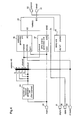
- Figure 1 is a block diagram illustrating a structure of the error correction apparatus according to the first embodiment.
- An input terminal 1 receives a reset signal (rst) when the head position of a frame that is synchronized with data (data1) is determined or changed.
- An input terminal 2 receives a frame sync signal (fsync) that is synchronized with the data (data1).
- An input terminal 3 receives a Reed-Solomon packet head signal (psync1) that is synchronized with the data (data1).
- An input terminal 4 receives the data (data1).
- a deinterleave mode generation unit 5 generates a deinterleave mode (dimode).
- a deinterleave unit 8 subjects the inputted data (data1) to deinterleaving corresponding to the deinterleave mode (dimode) generated by the deinterleave mode generation unit 5.
- a Reed-Solomon decoding unit 10 subjects deinterleaved data (data2) to Reed-Solomon decoding.
- An output terminal 11 outputs a Reed-Solomon packet head signal (psync3) that is synchronized with data (data3), to the outside.
- An output terminal 12 outputs a Reed-Solomon packet error signal (perror) that is synchronized with the data (data3), to the outside.
- An output terminal 13 outputs Reed-Solomon decoded data (data3) resulting from the error correction, to the outside.
- Figure 2 is a block diagram illustrating a structure of the deinterleave mode generation unit of the error correction apparatus according to the first embodiment.
- An input terminal 21 receives the reset signal (rst).
- An input terminal 23 receives the Reed-Solomon packet head signal (psync3).
- An input terminal 24 receives the error signal (perror) of each Reed-Solomon packet.
- a delay amount calculation unit 25 calculates an amount of delay corresponding to each deinterleave mode.
- a deinterleave mode change signal generation unit 26 generates a deinterleave mode change signal (chmode).
- a deinterleave mode change unit 27 changes a deinterleave mode signal (dimode).
- An output terminal 28 outputs the change deinterleave mode to the deinterleave unit 8.
- the convolutional deinterleave unit is capable of deinterleaving data from the register.
- the numbers of channels are all powers of 2 (see figure 5).
- the deinterleave unit 8 comprises, as shown in figure 4, a number-of-channel generation unit 44, a selector 45, an address generation unit 46, a write enable generation unit 47, a delay unit 48 and a memory (RAM) 49, one memory can be commonly used in plural modes. Consequently, plural deinterleave unit corresponding to respective modes are not required, thereby reducing the circuit scale.
- An input terminal 40 receives the frame sync signal (fsync).
- An input terminal 41 receives the Reed-Solomon packet head signal (psync1).
- An input terminal 42 receives the inputted data (data1).
- An input terminal 43 receives the deinterleave mode (dimode).
- the number-of-channel generation unit 44 generates the numbers of channels, and outputs all 7 bits, low-order 6 bits, low-order 5 bits, low-order 4 bits, and low-order 3 bits, corresponding to the numbers of channels, to the selector 45.
- the selector 45 selects one of the numbers of channels (channel) which are generated by the number-of-channel generation unit 44, i.e., default, the number of channels 3, the number of channels 5, the number of channels 7, and the number of channels 9, in accordance with the deinterleave mode (dimode) that is inputted through the input terminal 43.
- the address generation unit 46 generates a memory address (AD) for the deinterleaving.
- the write enable apparatus 47 generates a write enable signal (NWE).
- the delay unit 48 outputs a Reed-Solomon packet head signal (psync2) that is synchronized with data (data2), to an output terminal 50.
- the memory 49 outputs the deinterleaved data (data2) to an output terminal 51
- the output terminal 50 outputs the Reed-Solomon packet head signal (psync2) that is synchronized with the data (data2) to the Reed-Solomon decoding unit 10.
- the output terminal 51 outputs the deinterleaved data (data2) to the Reed-Solomon decoding unit 10.
- the data (data1), the frame sync signal (fsync) that is synchronized with the data (data1), and the Reed-Solomon packet head signal (psync1) that is synchronized with the data (data1) are inputted to the deinterleave unit 8 through the input terminals 2 to 4.
- the reset signal (rst) is inputted to the deinterleave mode generation unit 5 through the input terminal 1.
- the deinterleave mode generation unit 5 When the Reed-Solomon packet head signal (psync3) and the Reed-Solomon packet error signal (perror) which are outputted from the Reed-Solomon decoding unit 10, and the reset signal (rst) are inputted, the deinterleave mode generation unit 5 generates a deinterleave mode (dimode) and outputs the same to the deinterleave unit 8.
- the deinterleave unit 8 deinterleaves the data (data1), and outputs deinterleaved data (data2) and a Reed-Solomon packet head signal (psycn2) that is synchronized with the deinterleaved data (data2), to the Reed-Solomon decoding unit 10.
- the Reed-Solomon decoding unit 10 subjects the data (data2) to Reed-Solomon decoding, and outputs a Reed-Solomon decoded data (data3) resulting from the error correction to the output terminal 13, as well as outputs a Reed-Solomon packet head signal (psync3) that is synchronized with the decoded data (data3) to the output terminal 11 and the deinterleave mode generation unit 5, and further outputs a Reed-Solomon packet error signal (perror) that is synchronized with the data (data3) to the output terminal 12 and the deinterleave mode generation unit 5.
- perror Reed-Solomon packet error signal
- the delay amount calculation unit 25 switches a delay amount calculation completion signal (dlyflag) OFF, resets a counter (not shown) at zero, and starts counting. Then, it counts up the delay amount that is processing time of the deinterleave unit 8 and the Reed-Solomon decoding unit 10, for each deinterleave mode (dimode) outputted from the deinterleave mode change unit 27.
- the apparatus 25 switches the delay amount calculation completion signal (dlyflg) ON, and outputs the signal to the deinterleave mode change signal generation unit 26.
- the deinterleave mode change signal generation unit 26 switches the deinterleave mode change signal (chmode) ON when the delay amount calculation completion signal (dlyflg) that is outputted from the delay amount calculation unit 25, the Reed-Solomon packet head signal (psycn3), and the Reed-Solomon packet error signal (perror) are ON (otherwise, switches the signal OFF), and outputs the change signal to the delay amount calculation unit 25 and the deinterleave mode change unit 27.
- the Reed-Solomon packet head signal (psync3) is ON, the signal indicates the head of the segment, and when the Reed-Solomon packet error signal (perror) is ON, the signal indicates that one segment was processed according to the Reed-Solomon, but could not be error-corrected.
- the deinterleave mode change unit 27 sets the deinterleave mode (dimode) at a predetermined initial value, then when the deinterleave mode change signal (chmode) is ON, changes the deinterleave mode (dimode) in a predetermined order, and outputs the changed deinterleave mode to the deinterleave unit 8.
- the deinterleave mode (dimode) is set at the predetermined initial value (S1), then the delay amount corresponding to the processing time of the deinterleave unit 8 and the Reed-Solomon decoding unit 10 is counted up (S2), and the number of errors corresponding to the Reed-Solomon packet error signal (perror) is compared with a threshold, i.e., switching criterion (S3).
- a threshold i.e., switching criterion
- the threshold as the switching criterion may be set from the outside or may be decided by a register or the like.
- the deinterleave mode is changed in the specified order, and the changed mode is outputted to the deinterleave unit 8 (S4).
- the number-of-channel generation unit 44 When the frame sync signal (fsync) that is inputted through the input terminal 40 is switched ON, the number-of-channel generation unit 44 resets the counter at zero, repeats counting-up from zero to 127, generates the numbers of channels (channel) for all deinterleave modes from the counter outputs, and outputs the numbers of channels to the selector 45.
- the selector 45 selects one of the numbers of channels (channel) in accordance with the value of the deinterleave mode (dimode) that is inputted through the input terminal 43, and outputs the selected number to the address generation unit 46 and the write enable generation unit 47.
- the address generation unit 46 identifies the depth in the convolutional deinterleave on the basis of the number of channels (channel) selected by the selector 45 and the deinterleave mode (dimode) that is inputted through the input terminal 43, generates a memory address (AD), and outputs the generated address to the memory 49.
- the write enable generation unit 47 generates a write enable signal (NEW) on the basis of the number of channels (channel) selected by the selector 45 and the frame sync signal (fsync) that is inputted through the input terminal 40, and outputs the generated write enable signal to the memory 49.
- NW write enable signal
- the delay unit 48 calculates a delay amount of Reed-Solomon packet head signal (psync1) corresponding to each deinterleaving, in accordance with the deinterleave mode (dimode), and outputs a Reed-Solomon packet head signal (psync2) that is synchronized with output (data2) of the memory 49, to the output terminal 50.
- the memory 49 deinterleaves inputted data (DI) on the basis of the memory address (AD) and the write enable signal (NEW), and outputs deinterleaved data (DO) to the output terminal 51.
- DI inputted data
- AD memory address
- NW write enable signal
- the Reed-Solomon packet head signal and the Reed-Solomon packet error signal which are outputted from the Reed-Solomon decoding unit 10 are used as trigger signals for changing the deinterleave mode, and further, the deinterleave mode generation unit 5 is provided for changing the deinterleave mode on the basis of the trigger signals. Accordingly, the lead-in time for the deinterleave mode judgment is reduced, and consequently the lead-in time of the demodulation system at the reset or switching of modes can be reduced. Further, when the mode is changed, the time taken to display images on a television of the like is shorter than in the case of the prior art, thereby improving the responsibility at the power-on or switching of modes.
- Figure 6 is a block diagram illustrating a structure of an error correction apparatus according to the second embodiment.
- the same reference numerals as those in figure 1 denotes the same or corresponding components, and their descriptions are omitted here.
- An input terminal 6 receives a select signal (dimodesel) for switching between a deinterleave mode that is inputted through an input terminal 7 and a deinterleave mode that is obtained by the deinterleave mode generation unit 5.
- the input terminal 7 receives a deinterleave mode (dimode) that is designated from the outside.
- a selector 9 selects either the deinterleave mode (dimode) that is outputted from the deinterleave mode generation unit 5 or the deinterleave mode (dimode) that is inputted through the input terminal 7, in accordance with the select signal (dimodesel) that is inputted through the input terminal 6.
- a deinterleave unit 8 subjects the inputted data (data1) to deinterleaving corresponding to the deinterleave mode (dimode) that is selected by the selector 9.
- the data (data1), the frame sync signal (fsync) that is synchronized with the data (data1), and the Reed-Solomon packet head signal (psync1) that is synchronized with the data (data1) are inputted to the deinterleave unit 8 through the input terminals 2 to 4.
- the reset signal (rst) is inputted to the deinterleave mode generation unit 5 through the input terminal 1.
- a Reed-Solomon packet head signal (psync3) and a Reed-Solomon packet error signal (perror) that are outputted from the Reed-Solomon decoding unit 10, and the reset signal (rst) are inputted
- the deinterleave mode generation unit 5 generates a deinterleave mode (dimode) and outputs the same to the selector 9.
- the selector 9 switches between the deinterleave mode (dimode) that is outputted from the deinterleave mode generation unit 5 and the deinterleave mode (dimode) that is designated from the outside through the input terminal 7, in accordance with the select signal (dimodesel) that is inputted through the input terminal 6, and outputs the selected deinterleave mode (dimode) to the deinterleave unit 8.
- the deinterleave unit 8 deinterleaves the data (data1), and outputs deinterleaved data (data2) and a Reed-Solomon packet head signal (psync2) that is synchronized with the data (data2) to the Reed-Solomon decoding unit 10.
- the Reed-Solomon decoding unit 10 subjects the data (data2) to Reed-Solomon decoding and outputs Reed-Solomon decoded data (data3) resulting from the error correction, to the output terminal 13, as well as outputs a Reed-Solomon packet head signal (psync3) that is synchronized with the data (data3) to the output terminal 11 and the deinterleave mode generation unit 5, and further outputs a Reed-Solomon packet error signal (perror) that is synchronized with the data (data3) to the output terminal 12 and the deinterleave mode generation unit 5.
- perror Reed-Solomon packet error signal
- either of the deinterleave mode that is generated by the deinterleave mode generation unit 5 or the deinterleave mode inputted from outside is selected in accordance with the select signal from outside, whereby the leading into the selected deinterleave mode is completed in the minimum lead-in time, and the lead-in time of the demodulation system at the reset or switching of modes can be reduced. Consequently, when the mode is changed, the time taken to display images on a television or the like is shorter than that in the prior art, thereby increasing the responsibility at the power-on or the switching of modes.
- the deinterleave unit performs the convolutional deinterleave, using the information concerning the number of channels and the depth corresponding to each deinterleave mode.
- this apparatus performs block deinterleave, using information concerning the number of rows and the number of columns corresponding to each deinterleave mode, the deinterleave unit generates the respective numbers of rows for all deinterleave modes upon receipt of the frame sync signal, then selects the number of rows corresponding to a deinterleave mode generated by the deinterleave mode generation unit, among the numbers of rows for all deinterleave modes, identifies the number of columns in the block deinterleave on the basis of the selected number of rows and the deinterleave mode, and then generates a memory address. Accordingly, the same effects as those in the case of convolutional deinterleave are obtained.
Landscapes
- Physics & Mathematics (AREA)
- Engineering & Computer Science (AREA)
- Probability & Statistics with Applications (AREA)
- Theoretical Computer Science (AREA)
- Mathematical Physics (AREA)
- Algebra (AREA)
- General Physics & Mathematics (AREA)
- Pure & Applied Mathematics (AREA)
- Multimedia (AREA)
- Signal Processing (AREA)
- Error Detection And Correction (AREA)
- Detection And Prevention Of Errors In Transmission (AREA)
Abstract
Description
Claims (18)
- An error correction apparatus which performs error correction of received data according to a deinterleave mode inserted in the received data, comprising:a deinterleave unit for receiving a frame sync signal and a Reed-Solomon packet head signal which are synchronized with the received data, deinterleaving the received data, and outputting deinterleaved data and a Reed-Solomon packet head signal that is synchronized with the deinterleaved data;a Reed-Solomon decoding unit for receiving the Reed-Solomon packet head signal that is synchronized with the deinterleaved data, Reed-Solomon decoding the deinterleaved data, and outputting Reed-Solomon decoded data resulting from error correction as well as outputting a Reed-Solomon packet head signal and a Reed-Solomon packet error signal which are synchronized with the Reed-Solomon decoded data; anda deinterleave mode generation unit for receiving the Reed-Solomon packet head signal and the Reed-Solomon packet error signal as trigger signals for deinterleave changing, and generating the deinterleave mode.
- The error correction apparatus of Claim 1 whereinthe deinterleave mode generation unit includes:a calculation means for calculating a switching comparison value from the trigger signals;a comparison means for comparing the switching comparison value with a predetermined deinterleave mode switching criterion; anda changing means for, when the switching comparison value satisfies the deinterleave mode switching criterion, changing the deinterleave mode from a deinterleave mode initial value in accordance with a deinterleave mode switching order, and outputting a changed deinterleave mode.
- The error correction apparatus of Claim 1 or 2 whereinthe deinterleave unit includes:an address generation unit for receiving the frame sync signal, generating memory addresses corresponding to respective deinterleave modes, selecting among the generated memory addresses a memory address corresponding to the deinterleave mode generated by the deinterleave mode generation unit, and outputting the selected memory address; anda memory for deinterleaving the received data in accordance with the selected memory address and outputting deinterleaved data.
- The error correction apparatus of Claim 3 whereinthe deinterleave unit performs convolutional deinterleave using information concerning the number of channels and a depth for each deinterleave mode.
- The error correction apparatus of Claim 4 whereinthe deinterleave unit includes:a number-of-channel counter for outputting respective numbers of channels for all deinterleave modes upon receipt of the frame sync signal; anda selector for receiving the deinterleave mode generated by the deinterleave mode generation unit, selecting one output of the number-of-channel counter in accordance with the generated deinterleave mode, and outputting the selected output to the address generation unit, andthe address generation unit identifies a depth for the convolutional deinterleave on the basis of the deinterleave mode generated by the deinterleave mode generation unit and the number of channels, and generates the memory address.
- The error correction apparatus of Claim 3 whereinthe deinterleave unit performs block deinterleave using information concerning the number of rows and the number of columns for each deinterleave mode.
- The error correction apparatus of Claim 6 whereinthe deinterleave unit generates respective numbers of rows for all deinterleave modes upon receipt of the frame sync signal, then selects, among the generated numbers of rows for all deinterleave modes, a number of rows corresponding to the deinterleave mode generated by the deinterleave mode generation unit, identifies a number of columns in the block deinterleave on the basis of the selected number of rows and the generated deinterleave modes, and generates the memory address.
- The error correction apparatus of Claim 1 whereinthe deinterleave mode generation unit generates the deinterleave mode when a reset signal is inputted upon change of a frame head position.
- The error correction apparatus of Claim 1 whereina selector for selecting either the deinterleave mode outputted from the deinterleave mode generation apparatus, or a deinterleave mode inputted from outside, in accordance with a select signal that is inputted from outside, and outputting the selected deinterleave mode is provided between the deinterleave mode generation unit and the deinterleave unit.
- An error correction method for performing error correction of received data according to a deinterleave mode inserted in the received data, comprising:a deinterleave step of receiving the deinterleave mode, and a frame sync signal and a Reed-Solomon packet head signal which are synchronized with the received data;a Reed-Solomon decoding step of receiving deinterleaved data and a Reed-Solomon packet head signal that is synchronized with the deinterleaved data, and Reed-Solomon decoding the deinterleaved data; anda deinterleave mode changing step of changing the deinterleave mode using a Reed-Solomon packet head signal and a Reed-Solomon packet error signal which are synchronized with the Reed-Solomon decoded data as trigger signals.
- The error correction method of Claim 10 whereinin the deinterleave mode changing step,a switching comparison value is calculated from the trigger signals, the calculated switching comparison value is compared with a deinterleave mode switching criterion, and when the switching comparison value satisfies the deinterleave mode switching criterion, the deinterleave mode is changed from a deinterleave mode initial value in accordance with a deinterleave mode switching order.
- The error correction method of Claim 10 or 11 whereinin the deinterleave step,address counters for respective deinterleave modes are reset in accordance with the frame sync signal, the respective address counters count up simultaneously, one of outputs from the address counters is selected in accordance with the changed deinterleave mode, to generate a memory address, and the received data is deinterleaved on the basis of the memory address.
- The error correction method of Claim 12 whereinin the deinterleave step, convolutional deinterleave is performed using the number of channels and a depth for each deinterleave mode.
- The error correction method of Claim 13 whereinin the deinterleave step,the number-of-channel counter for generating an address corresponding to each deinterleave mode is reset upon receipt of the frame sync signal, then when the deinterleave mode is changed, one output of the number-of-channel counter is selected, a depth in the convolutional deinterleave is identified in accordance with the selected number of channels and the changed deinterleave mode, then the memory address is generated, and the received data is deinterleaved on the basis of the memory address.
- The error correction method of Claim 12 whereinin the deinterleave step, block deinterleave is performed using the number of rows and the number of columns for each deinterleave mode.
- The error correction method of Claim 15 whereinin the deinterleave step,upon receipt of the frame sync signal, respective numbers of rows for all deinterleave modes are generated, a number of rows corresponding to the deinterleave mode that is changed in the deinterleave mode changing step is selected among the respective numbers of rows for all deinterleave modes, a number of columns in the block deinterleave is identified on the basis of the selected number of rows and the changed deinterleave mode, then the memory address is generated, and the block deinterleave is performed on the basis of the memory address.
- The error correction method of Claim 10 whereinin the deinterleave mode changing step, when a reset signal is inputted upon change of a frame head position, the deinterleave mode is changed.
- The error correction method of Claim 10 including:a selection step of selecting either the deinterleave mode changed in the deinterleave mode changing step, or a deinterleave mode inputted from outside, in accordance with a select signal that is inputted from outside, and outputting the selected deinterleave mode.
Applications Claiming Priority (2)
| Application Number | Priority Date | Filing Date | Title |
|---|---|---|---|
| JP2001147340 | 2001-05-17 | ||
| JP2001147340 | 2001-05-17 |
Publications (2)
| Publication Number | Publication Date |
|---|---|
| EP1259000A2 true EP1259000A2 (en) | 2002-11-20 |
| EP1259000A3 EP1259000A3 (en) | 2004-01-07 |
Family
ID=18992840
Family Applications (1)
| Application Number | Title | Priority Date | Filing Date |
|---|---|---|---|
| EP02010249A Withdrawn EP1259000A3 (en) | 2001-05-17 | 2002-05-17 | Apparatus and method for deinterleaving |
Country Status (4)
| Country | Link |
|---|---|
| US (1) | US6915479B2 (en) |
| EP (1) | EP1259000A3 (en) |
| KR (1) | KR100503532B1 (en) |
| CN (1) | CN1227819C (en) |
Families Citing this family (5)
| Publication number | Priority date | Publication date | Assignee | Title |
|---|---|---|---|---|
| US8099095B2 (en) * | 2003-02-25 | 2012-01-17 | Qualcomm Incorporated | Method and apparatus for controlling operation of an access terminal in a communication system |
| US8135935B2 (en) * | 2007-03-20 | 2012-03-13 | Advanced Micro Devices, Inc. | ECC implementation in non-ECC components |
| US20130322578A1 (en) * | 2012-05-30 | 2013-12-05 | Lsi Corporation | Systems and Methods for Data Processing Including EET Feedback |
| EP3242486A4 (en) * | 2014-12-29 | 2018-08-01 | LG Electronics Inc. -1- | Broadcast signal transmission apparatus, broadcast signal reception apparatus, broadcast signal transmission method, and broadcast signal reception method |
| US11663073B2 (en) | 2020-12-10 | 2023-05-30 | Advanced Micro Devices, Inc. | Method and apparatus for data protection in memory devices |
Family Cites Families (14)
| Publication number | Priority date | Publication date | Assignee | Title |
|---|---|---|---|---|
| JPH02113787A (en) | 1988-10-24 | 1990-04-25 | Matsushita Electric Ind Co Ltd | Inbetween-frame deinterleave switching circuit |
| JPH0531973A (en) | 1991-07-29 | 1993-02-09 | Canon Inc | Image recording device |
| JPH07254862A (en) | 1994-03-15 | 1995-10-03 | Sony Corp | Interleave circuit and deinterleave circuit |
| US5835165A (en) * | 1995-06-07 | 1998-11-10 | Lsi Logic Corporation | Reduction of false locking code words in concatenated decoders |
| US5745528A (en) * | 1995-07-13 | 1998-04-28 | Zenith Electronics Corporation | VSB mode selection system |
| KR100222680B1 (en) * | 1996-07-09 | 1999-10-01 | 윤종용 | Method and apparatus for switching of operating mode in a high definition television system |
| US5996103A (en) | 1996-07-31 | 1999-11-30 | Samsung Information Systems America | Apparatus and method for correcting errors in a communication system |
| US5912898A (en) | 1997-02-27 | 1999-06-15 | Integrated Device Technology, Inc. | Convolutional interleaver/de-interleaver |
| JPH10303854A (en) | 1997-04-23 | 1998-11-13 | Matsushita Electric Ind Co Ltd | Deinterleave device |
| US6029264A (en) * | 1997-04-28 | 2000-02-22 | The Trustees Of Princeton University | System and method for error correcting a received data stream in a concatenated system |
| US6067646A (en) | 1998-04-17 | 2000-05-23 | Ameritech Corporation | Method and system for adaptive interleaving |
| US6411654B1 (en) | 1998-04-27 | 2002-06-25 | Matsushita Electric Industrial Co., Ltd. | Convolutional interleaver, convolutional deinterleaver, convolutional interleaving method, and convolutional deinterleaving method |
| JP2961105B1 (en) | 1998-06-19 | 1999-10-12 | 株式会社次世代デジタルテレビジョン放送システム研究所 | OFDM receiver |
| US6014411A (en) * | 1998-10-29 | 2000-01-11 | The Aerospace Corporation | Repetitive turbo coding communication method |
-
2002
- 2002-05-16 US US10/146,127 patent/US6915479B2/en not_active Expired - Fee Related
- 2002-05-17 CN CNB021251762A patent/CN1227819C/en not_active Expired - Fee Related
- 2002-05-17 KR KR10-2002-0027318A patent/KR100503532B1/en not_active Expired - Fee Related
- 2002-05-17 EP EP02010249A patent/EP1259000A3/en not_active Withdrawn
Also Published As
| Publication number | Publication date |
|---|---|
| US6915479B2 (en) | 2005-07-05 |
| US20020174398A1 (en) | 2002-11-21 |
| CN1387323A (en) | 2002-12-25 |
| CN1227819C (en) | 2005-11-16 |
| KR100503532B1 (en) | 2005-07-25 |
| KR20020088384A (en) | 2002-11-27 |
| EP1259000A3 (en) | 2004-01-07 |
Similar Documents
| Publication | Publication Date | Title |
|---|---|---|
| EP0801502B1 (en) | Code sequence detection in a trellis decoder | |
| US7023488B2 (en) | Circuit and method for live switching of digital video programs containing embedded audio data | |
| US5208666A (en) | Error detection for digital television equipment | |
| US7133481B2 (en) | Synchronization detection apparatus | |
| KR101274394B1 (en) | Address generator for an interleaver memory and a deinterleaver memory | |
| US7110041B2 (en) | Teletext data separation apparatus | |
| US6915479B2 (en) | Apparatus and method for error correction | |
| KR100450320B1 (en) | Method/Module of Digital TV image signal processing with Auto Error Correction | |
| US4679082A (en) | Code transmission system character broadcasting receiver | |
| US5778010A (en) | Method and device for correcting packet data error and packet receiver | |
| CN117130430A (en) | Real-time counter, method and device for controlling real-time counter and storage medium | |
| JP4416543B2 (en) | Data detection device and multi-channel data detection device | |
| EP0818900B1 (en) | Digital signal multiplexing apparatus | |
| US6744837B1 (en) | Clock switching circuit | |
| JP3593115B2 (en) | Error correction device and error correction method | |
| JPH0546131B2 (en) | ||
| US6728926B1 (en) | Encoding rate detection method and encoding rate detection device | |
| US12342032B2 (en) | Control integrated circuit for maintaining video output to conditional access module with aid of reference clock regeneration, associated television receiver and associated method | |
| EP1091579B1 (en) | Trellis demapper for Trellis decoder | |
| US20060001769A1 (en) | Apparatus and method for detecting synchronization signal of data signal utilizing synchronization symbols | |
| US20070189233A1 (en) | Apparatus and method for processing input/output data in communication system | |
| JP3753006B2 (en) | Communication device and communication method | |
| CN115687188A (en) | Display interface signal output conversion circuit and related method | |
| JPH0595566A (en) | Digital signal transmitter | |
| US20090003444A1 (en) | Method and apparatus for video enhancement by reorganizing group of pictures |
Legal Events
| Date | Code | Title | Description |
|---|---|---|---|
| PUAI | Public reference made under article 153(3) epc to a published international application that has entered the european phase |
Free format text: ORIGINAL CODE: 0009012 |
|
| AK | Designated contracting states |
Kind code of ref document: A2 Designated state(s): AT BE CH CY DE DK ES FI FR GB GR IE IT LI LU MC NL PT SE TR |
|
| AX | Request for extension of the european patent |
Free format text: AL;LT;LV;MK;RO;SI |
|
| PUAL | Search report despatched |
Free format text: ORIGINAL CODE: 0009013 |
|
| RIC1 | Information provided on ipc code assigned before grant |
Ipc: 7H 04L 1/00 B Ipc: 7H 03M 13/27 A |
|
| AK | Designated contracting states |
Kind code of ref document: A3 Designated state(s): AT BE CH CY DE DK ES FI FR GB GR IE IT LI LU MC NL PT SE TR |
|
| AX | Request for extension of the european patent |
Extension state: AL LT LV MK RO SI |
|
| 17P | Request for examination filed |
Effective date: 20040331 |
|
| AKX | Designation fees paid |
Designated state(s): DE FR GB |
|
| 17Q | First examination report despatched |
Effective date: 20041027 |
|
| RAP1 | Party data changed (applicant data changed or rights of an application transferred) |
Owner name: PANASONIC CORPORATION |
|
| STAA | Information on the status of an ep patent application or granted ep patent |
Free format text: STATUS: THE APPLICATION IS DEEMED TO BE WITHDRAWN |
|
| 18D | Application deemed to be withdrawn |
Effective date: 20121201 |