EP1258877A2 - Media storage system - Google Patents
Media storage system Download PDFInfo
- Publication number
- EP1258877A2 EP1258877A2 EP02253418A EP02253418A EP1258877A2 EP 1258877 A2 EP1258877 A2 EP 1258877A2 EP 02253418 A EP02253418 A EP 02253418A EP 02253418 A EP02253418 A EP 02253418A EP 1258877 A2 EP1258877 A2 EP 1258877A2
- Authority
- EP
- European Patent Office
- Prior art keywords
- media
- cables
- picker assembly
- cartridge
- assembly
- Prior art date
- Legal status (The legal status is an assumption and is not a legal conclusion. Google has not performed a legal analysis and makes no representation as to the accuracy of the status listed.)
- Granted
Links
- 230000008878 coupling Effects 0.000 claims description 4
- 238000010168 coupling process Methods 0.000 claims description 4
- 238000005859 coupling reaction Methods 0.000 claims description 4
- 238000013500 data storage Methods 0.000 description 11
- 230000000712 assembly Effects 0.000 description 10
- 238000000429 assembly Methods 0.000 description 10
- 230000007246 mechanism Effects 0.000 description 10
- 238000001514 detection method Methods 0.000 description 6
- 230000009977 dual effect Effects 0.000 description 5
- 230000007257 malfunction Effects 0.000 description 5
- 210000003813 thumb Anatomy 0.000 description 5
- 238000006073 displacement reaction Methods 0.000 description 4
- 238000000034 method Methods 0.000 description 2
- 238000012544 monitoring process Methods 0.000 description 2
- 238000010276 construction Methods 0.000 description 1
- 238000003032 molecular docking Methods 0.000 description 1
Images


Classifications
-
- G—PHYSICS
- G11—INFORMATION STORAGE
- G11B—INFORMATION STORAGE BASED ON RELATIVE MOVEMENT BETWEEN RECORD CARRIER AND TRANSDUCER
- G11B15/00—Driving, starting or stopping record carriers of filamentary or web form; Driving both such record carriers and heads; Guiding such record carriers or containers therefor; Control thereof; Control of operating function
- G11B15/675—Guiding containers, e.g. loading, ejecting cassettes
- G11B15/68—Automatic cassette changing arrangements; automatic tape changing arrangements
- G11B15/682—Automatic cassette changing arrangements; automatic tape changing arrangements with fixed magazines having fixed cassette storage cells, e.g. in racks
- G11B15/6835—Automatic cassette changing arrangements; automatic tape changing arrangements with fixed magazines having fixed cassette storage cells, e.g. in racks the cassettes being transferred to a fixed recorder or player using a moving carriage
-
- G—PHYSICS
- G11—INFORMATION STORAGE
- G11B—INFORMATION STORAGE BASED ON RELATIVE MOVEMENT BETWEEN RECORD CARRIER AND TRANSDUCER
- G11B17/00—Guiding record carriers not specifically of filamentary or web form, or of supports therefor
- G11B17/22—Guiding record carriers not specifically of filamentary or web form, or of supports therefor from random access magazine of disc records
- G11B17/225—Guiding record carriers not specifically of filamentary or web form, or of supports therefor from random access magazine of disc records wherein the disks are transferred from a fixed magazine to a fixed playing unit using a moving carriage
Definitions
- This invention relates to a media picker assembly and to a media storage system comprising a media picker assembly. It relates in general to data storage systems for handling and storing data cartridges, and more particularly, to redundancy systems and methods to improve the reliability and speed of a data storage system.
- Such data storage systems are often referred to as "juke box" data storage systems, particularly if they can accommodate a large number of individual data cartridges.
- a typical juke box data storage system may include one or more different types of cartridge receiving devices for holding the various data cartridges.
- one type of cartridge receiving device may include a cartridge storage rack or "magazine" while another type of cartridge receiving device may include a cartridge read/write device.
- the cartridge storage racks or magazines provide storage locations for the data cartridges and are often arranged so that they form one or more vertical stacks, although other configurations are possible.
- the cartridge read/write device may be located at any convenient location within the data storage system.
- the data storage system may also be provided with a moveable cartridge picker assembly or "picker” for transporting the data cartridges between the various cartridge receiving devices, e.g., between the cartridge storage racks and the cartridge read/write devices.
- a typical cartridge picker assembly or picker may also be provided with a cartridge plunge mechanism or "thumb” assembly for engaging the various data cartridges contained in the cartridge receiving devices and for drawing them into the picker.
- a picker positioning system associated with the cartridge picker assembly may be used to move the cartridge picker assembly along the various cartridge receiving devices.
- Data storage systems of the type described above are usually connected to a host computer system which may be used to access or store data on the data cartridges. For example, if the host computer system issues a request for data contained on a particular data cartridge, a control system associated with the data storage system will actuate the picker positioning system to move the picker assembly along the cartridge storage racks until the picker assembly is positioned adjacent the desired data cartridge. The cartridge plunge mechanism or "thumb" assembly associated with the picker assembly may then remove the data cartridge from the cartridge storage rack and draw it into the picker assembly. The picker positioning system may then be actuated to move the picker assembly to the appropriate cartridge read/write device.
- the thumb assembly may insert the selected data cartridge into the cartridge read/write device so that the host computer may thereafter read data from or write data to the data cartridge. After the read/write operation is complete, the thumb assembly may be actuated to remove the data cartridge from the cartridge read/write device. The picker assembly may thereafter return the data cartridge to the appropriate location in the cartridge storage rack.
- a media picker assembly includes a frame, a plunge assembly operable to travel along a predetermined axis of the frame to engage and disengage a media cartridge, and first and second cables coupled to the frame for transmitting first and second predetermined sets of signals, respectively.
- a media storage system in another embodiment, includes a media cartridge picker assembly operable to traverse along a predetermined path, and first and second cables coupled to the media cartridge picker assembly for transmitting first and second predetermined sets of signals, respectively.
- the first cable coupling the media cartridge picker assembly to a first point proximate to the first end of the path and the second cable coupling the media cartridge picker assembly to a second point proximate to the second end of the path.
- a method includes the steps of monitoring a predetermined signal value carried in an active cable coupled to a media cartridge picker assembly of a multi-layer media storage system, switching a standby cable coupled to the media cartridge picker assembly to active status in response to the predetermined signal value being different from an expected signal value, and switching the active cable to standby status.
- FIGURES 1 through 5 of the drawings like numerals being used for like and corresponding parts of the various drawings.
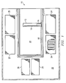
- FIGURE 1 is a simplified plan view of a media storage device 10.
- Media storage device 10 includes a data cartridge picker assembly 12 with a cartridge plunge assembly 14 that is operable to travel along a guide 16 to move to and away from a data cartridge access end of picker assembly 12.
- picker assembly 12 is further operable to move along a generally U-shaped guide 18 within a translate frame 20 of media storage device 10 to travel a generally U-shaped path to access data cartridges contained in storage racks or magazines 24 and 25 and to access media read/write device stacks 26.
- Rack and pinion drive assemblies may be used to move cartridge plunge assembly along guide 16 as well as along guide 18.
- Picker/translate frame assembly 20 further includes a lift motor 36 and rack and pinion (not shown) for vertical displacement to access the multiple vertically stacked layers.
- Autochanger media storage devices of the type shown and described herein are well known. Details related to exemplary mechanisms for vertical, lateral and plunging axes of displacement are well known and are described, for example, in U.S. Patent No. 5,596,556 to Luffel et al. and assigned to Hewlett-Packard Company. Details related to exemplary mechanisms for a cartridge plunge mechanism are described, for example, in U.S. Patent No. 6,104,693 issued to Coffin et al. and assigned to Hewlett-Packard Company. Details related to exemplary mechanisms for a thumb reference and drive mechanism are described, for example, in U.S. Patent No. 6,157,513 issued to Coffin et al. and assigned to Hewlett-Packard Company.
- FIGURE 2 is a simplified side view of a portion of a media storage device 10 having a data cartridge picker assembly 12 accessing multiple drive module bays 26 and multiple data magazine bays 38.
- Picker assembly 12 includes a cartridge plunge assembly 14 that is capable of horizontal displacement within picker assembly 12 to access data cartridges to and from magazine bays 38 and drive module bays 26
- Picker assembly 12 includes redundant umbilical cables 30 and 32 according to the teachings of the present invention.
- Upper umbilical cable 30 may be attached to a point on the media storage housing at or near the upper reaches of translate frame 20.
- Lower umbilical cable 32 may be attached to a point on the media storage housing at or near the lower reaches of translate frame 20.
- Umbilical cables 30 and 32 are preferably self-retracting such as a Z-fold cable which automatically folds to take up slack in the cable. For example, as picker assembly 12 moves up, slack in upper umbilical cable 30 is folded into storage tray 34 disposed on top of picker assembly 12; as picker assembly 12 moves down, slack in lower umbilical cable 32 is folded and collected onto the bottom floor.
- the description and drawings herein assume vertical displacement of the picker assembly, different picker configurations are possible. For example, the picker assembly may travel in a horizontal axis to reach the media cartridge bays.
- Umbilical cables 30 and 32 preferably carry identical signals to and from translate frame assembly 20, such as power, ground, status signals, control signals, etc.
- Umbilical cables 30 and 32 preferably operate in active/standby modes. When the active umbilical cable is severed or malfunctions, the standby cable is immediately brought into active mode so that normal operations continue with minimal interruption.
- the detection of cable malfunction or severance may be achieved by monitoring one or more predetermined signals that are maintained at constant or known voltages or values. Any variation in this detection signal may indicate the presence of malfunction or cable breakage.
- a predetermined signal value may be generated by a media storage controller (not shown) and sent to picker assembly 12, which monitors its value.
- Picker assembly 12 also sends the detection signal back to the controller, which monitors its detection signal value for signs of cable malfunction and breakage. Detection of signal variation by either the picker assembly or the controller is indicative of the need to switch to the redundant backup cable.
- FIGURE 3 is a simplified side view of a portion of media storage device 10 with an embodiment of dual data cartridge picker assemblies 20 and 20' according to the teachings of the present invention.
- Upper picker assembly 20 and lower picker assembly 20' may be of identical construction and functionality.
- Picker assembly 20 includes a cartridge plunge mechanism 12 and a Z-fold umbilical cable 42 attached to a high point on the picker translator frame.
- picker assembly 20' includes a cartridge plunge mechanism 12' and a Z-fold umbilical cable 44 coupled to a low point on the picker translator frame.
- Picker assemblies 20 and 20' are capable of operating independently and in a coordinated manner together to access the media cartridges.
- slack in upper umbilical cable 42 is folded into a storage tray (not shown) disposed on top of picker assembly 20.
- slack in lower umbilical cable 44 is folded and collected onto the bottom floor of picker translate frame.
- cable self-retracting mechanisms may be used to gather up slack in the cable to prevent entanglement.
- FIGURES 4 and 5 are simplified front views of two exemplary embodiments of a portion of media storage device 10 having dual data cartridge picker assemblies according to the teachings of the present invention.
- an upper picker parking area 50 and a lower picker parking area 50' additionally provide docking spaces to upper and lower picker assemblies 20 and 20', respectively, when either picker assembly is not in use.
- the inactive picker assembly When parked in one of the parking areas 50 or 50', the inactive picker assembly is out of the range of the active picker assembly and thereby not obstructing its access to any media storage cartridge bay.
- Parking areas 50 and 50' may be any available space that a malfunctioning picker assembly may retreat to and not obstruct the access to any media storage bay or drive module bays.
- both picker assemblies 20 and 20' operate together to access media storage cartridges in a less time.
- Upper picker assembly 20 may be assigned to the upper media storage cartridges and lower picker assembly 20' may be assigned to the lower media storage cartridges. Because each picker assembly is closer to its destination, media access is speeded up. Furthermore, if a picker assembly experiences fault or malfunction, it may automatically return to its respective parking area so that the remaining picker assembly may continue to operate to cover the entire range of media storage bays without any service interruption. Alternatively, the picker assemblies may operate in active/standby mode during normal operations.
Landscapes
- Automatic Tape Cassette Changers (AREA)
- Automatic Disk Changers (AREA)
Abstract
Description
Many different types of data storage systems exist and are being used to store data cartridges at known locations and to retrieve desired data cartridges so that data may be written to or read from the data cartridges. Such data storage systems are often referred to as "juke box" data storage systems, particularly if they can accommodate a large number of individual data cartridges.
various data cartridges contained in the cartridge receiving devices and for drawing them into the picker. A picker positioning system associated with the cartridge picker assembly may be used to move the cartridge picker assembly along the various cartridge receiving devices.
cable coupling the media cartridge picker assembly to a first point proximate to the first end of the path and the second cable coupling the media cartridge picker assembly to a second point proximate to the second end of the path.
Claims (10)
- A media picker assembly (12), comprising:a frame (20);a plunge assembly (14) operable to travel along a predetermined axis of the frame (20) to engage and disengage a media cartridge; andfirst and second cables (30, 32) coupled to the frame (20) for communicating first and second predetermined sets of signals with the plunge assembly (14), respectively.
- A media picker assembly (12), as claimed in claim 1, wherein the first and second cables (30, 32) are coupled to opposing sides of the frame (20).
- A media picker assembly (12), as claimed in claim 1 or 2, wherein the first and second cables (30, 32) are Z-fold cables coupled to opposing sides of the frame (20).
- A media picker assembly (12), as claimed in any preceding claim, wherein the first and second cables (30, 32) are operable to automatically take up slack therein.
- A media picker assembly (12), as claimed in any preceding claim, wherein the first and second cables (30, 32) are redundant cables that communicate identical signals.
- A media storage system (10), comprising:a media cartridge picker assembly (12) operable to traverse along a predetermined path having first and second ends;first and second cables (30, 32) coupled to the media cartridge picker assembly (12) for transmitting first and second predetermined sets of signals, respectively; andthe first cable (30) coupling the media cartridge picker assembly (12) to a first point proximate to the first end of the path and the second cable (32) coupling the media cartridge picker assembly (12) to a second point proximate to the second end of the path.
- A media storage system (10), as claimed in claim 6, wherein the first and second cables (30, 32) are coupled to opposing sides of the media cartridge picker assembly (12).
- A media storage system (10), as claimed in claim 6 or 7, wherein the first and second cables (30, 32) are Z-fold cables coupled to opposing sides of the media cartridge picker assembly (12).
- A media storage system (10), as claimed in any of claims 6 to 8, wherein the first and second cables (30, 32) are operable to automatically take up slack therein.
- A media storage system (10), as claimed in any of claims 6 to 9, wherein the first and second cables (30, 32) are redundant cables that transmit identical signals.
Applications Claiming Priority (2)
| Application Number | Priority Date | Filing Date | Title |
|---|---|---|---|
| US861455 | 2001-05-18 | ||
| US09/861,455 US6778351B1 (en) | 2001-05-18 | 2001-05-18 | System and method of redundant cabling in a media storage system |
Publications (3)
| Publication Number | Publication Date |
|---|---|
| EP1258877A2 true EP1258877A2 (en) | 2002-11-20 |
| EP1258877A3 EP1258877A3 (en) | 2003-09-03 |
| EP1258877B1 EP1258877B1 (en) | 2008-09-24 |
Family
ID=25335839
Family Applications (1)
| Application Number | Title | Priority Date | Filing Date |
|---|---|---|---|
| EP02253418A Expired - Lifetime EP1258877B1 (en) | 2001-05-18 | 2002-05-16 | Media storage system |
Country Status (4)
| Country | Link |
|---|---|
| US (2) | US6778351B1 (en) |
| EP (1) | EP1258877B1 (en) |
| JP (1) | JP4039883B2 (en) |
| DE (1) | DE60229023D1 (en) |
Families Citing this family (6)
| Publication number | Priority date | Publication date | Assignee | Title |
|---|---|---|---|---|
| DE10136354B4 (en) * | 2001-07-26 | 2010-06-17 | Knapp Ag | Method and plant for picking with a container rack and associated storage and retrieval unit |
| US7133247B1 (en) * | 2003-12-04 | 2006-11-07 | Storage Technology Corporation | Self extending, retractable communications cable mechanism for storage library robotics module |
| US7146622B2 (en) * | 2003-12-04 | 2006-12-05 | Storage Technology Corporation | Storage library having free-hanging robot assembly |
| JP4095048B2 (en) * | 2004-07-28 | 2008-06-04 | 富士通株式会社 | Library device |
| JP4303253B2 (en) * | 2006-02-22 | 2009-07-29 | 富士通株式会社 | Library device and robot hand for library device |
| US7916423B2 (en) * | 2006-03-31 | 2011-03-29 | Spectra Logic Corporation | High density array system with active movable media drawers |
Family Cites Families (43)
| Publication number | Priority date | Publication date | Assignee | Title |
|---|---|---|---|---|
| US2940068A (en) * | 1957-10-28 | 1960-06-07 | Sperry Rand Corp | Large scale memory device |
| US3300572A (en) | 1963-12-18 | 1967-01-24 | Sanders Associates Inc | Extensible and retractable flexible circuit cable |
| US3490616A (en) * | 1967-11-07 | 1970-01-20 | Supreme Equip & Syst | Storage system with an automatic search and retrieval vehicle with an article guide means thereon |
| US3488430A (en) * | 1967-12-13 | 1970-01-06 | Honeywell Inc | Retractable cable forming clip |
| JPS56124159A (en) | 1980-02-29 | 1981-09-29 | Nippon Filing Co Ltd | Control device for information recording medium |
| JPS60209960A (en) | 1984-04-03 | 1985-10-22 | Sony Corp | Automatic tape cassette supply selective reproducer |
| AU4721285A (en) | 1985-04-08 | 1986-11-05 | Odetics, Inc. | Robotic materials handling system |
| JPS62213948A (en) | 1986-03-12 | 1987-09-19 | Daihatsu Motor Co Ltd | Backup device for unmanned process |
| US4820109A (en) * | 1986-04-11 | 1989-04-11 | Ampex Corporation | Bidirectional transfer mechanism |
| US4923053A (en) * | 1986-04-11 | 1990-05-08 | Ampex Corporation | Flexible member mounting assembly |
| US4864438A (en) | 1988-01-27 | 1989-09-05 | Munro Frederick G | Tape cartridge movement management in an automated tape cartridge library system |
| US5128912A (en) | 1988-07-14 | 1992-07-07 | Cygnet Systems Incorporated | Apparatus including dual carriages for storing and retrieving information containing discs, and method |
| US5101387A (en) | 1989-01-18 | 1992-03-31 | Hewlett-Packard Company | Lateral displacement control assembly for an optical disk handling system |
| JPH0310780A (en) | 1989-06-05 | 1991-01-18 | Mitsubishi Electric Corp | Industrial robot device |
| US4964120A (en) | 1989-09-08 | 1990-10-16 | Honeywell Inc. | Method of detecting a cable fault and switching to a redundant cable in a universal local area network |
| US5289589A (en) * | 1990-09-10 | 1994-02-22 | International Business Machines Corporation | Automated storage library having redundant SCSI bus system |
| DE4033880A1 (en) * | 1990-10-25 | 1992-04-30 | Triumph Adler Ag | CABLE ARRANGEMENT |
| US5429470A (en) | 1992-10-20 | 1995-07-04 | Odetics, Inc. | Inter-system transport mechanism for use with robotic data cartridge handling systems |
| US5427489A (en) | 1992-11-25 | 1995-06-27 | Gte Vantage Incorporated | Apparatus for controlling an automated cassette library |
| US5596556A (en) | 1993-02-18 | 1997-01-21 | Hewlett-Packard Company | Linear displacement and support apparatus for use in a cartridge handling system |
| US5431520A (en) | 1994-04-29 | 1995-07-11 | Eastman Kodak Company | Disc-shaped object storage and retrieval mechanism and method for using same |
| US5455810A (en) | 1994-06-03 | 1995-10-03 | Hewlett-Packard Company | Flexible member tensioning apparatus |
| US5544146B1 (en) | 1994-08-24 | 1998-03-03 | Hewlett Packard Co | Cartridge handling system |
| US5669749A (en) * | 1994-11-14 | 1997-09-23 | International Business Machines Corporation | Movable flexible ribbon cable and support band assembly |
| US5818723A (en) | 1994-12-22 | 1998-10-06 | International Business Machines Corporation | Quick access data storage library with backup capability |
| DE19517661A1 (en) | 1995-05-13 | 1996-11-14 | Nsm Ag | Playback and / or recording device for discs |
| US5781367A (en) | 1995-11-13 | 1998-07-14 | Advanced Digital Information Corporation | Library for storing data-storage media |
| US5906507A (en) * | 1997-08-07 | 1999-05-25 | Howard; James R. | Foldable electrical cord |
| JPH1173708A (en) | 1997-08-29 | 1999-03-16 | Fujitsu Ltd | Library device |
| US6434090B1 (en) * | 1997-09-16 | 2002-08-13 | International Business Machines Corporation | Automated data storage library with control path to shared robotic device via media drive |
| US6052341A (en) * | 1997-12-16 | 2000-04-18 | International Business Machines Corporation | Device element allocation manager and method for a multi-library system for multiple host connections |
| US6038490A (en) | 1998-01-29 | 2000-03-14 | International Business Machines Corporation | Automated data storage library dual picker interference avoidance |
| JP3535004B2 (en) * | 1998-02-27 | 2004-06-07 | 富士通株式会社 | Library device |
| US6160786A (en) | 1998-03-20 | 2000-12-12 | Hewlett-Packard Company | Cartridge engaging assembly with rack drive thumb actuator system |
| US6059509A (en) | 1998-07-01 | 2000-05-09 | Storage Technology Corporation | Library storage module with cartridge pass-through system |
| US6262863B1 (en) * | 1998-07-01 | 2001-07-17 | Storage Technology Corporation | Automated storage library with rail mechanism providing flexible robot access |
| US6490122B1 (en) * | 1998-08-28 | 2002-12-03 | Hewlett-Packard Company | System and method for providing power and control signals to a cartridge access device in a cartridge storage system |
| US6231291B1 (en) | 1999-03-18 | 2001-05-15 | Hewlett-Packard Company | Method and apparatus for exchanging data cartridges in a jukebox data storage system |
| US6183053B1 (en) | 1999-04-20 | 2001-02-06 | Hewlett-Packard Co. | Bezel assembly and method of production |
| US6309162B1 (en) | 1999-05-13 | 2001-10-30 | Hewlett-Packard Company | Data storage system with redundant media handling assemblies |
| US6194664B1 (en) * | 1999-06-07 | 2001-02-27 | International Business Machines Corporation | Apparatus for isolating and reinforcing bend corners of flexible cable |
| US6356803B1 (en) * | 2000-05-19 | 2002-03-12 | International Business Machines Corporation | Automated data storage library distributed control system |
| US6512962B2 (en) * | 2001-04-26 | 2003-01-28 | International Business Machines Corporation | Cabling picker in a library of stationary memory devices |
-
2001
- 2001-05-18 US US09/861,455 patent/US6778351B1/en not_active Expired - Lifetime
-
2002
- 2002-05-14 JP JP2002138277A patent/JP4039883B2/en not_active Expired - Fee Related
- 2002-05-16 DE DE60229023T patent/DE60229023D1/en not_active Expired - Lifetime
- 2002-05-16 EP EP02253418A patent/EP1258877B1/en not_active Expired - Lifetime
-
2004
- 2004-04-08 US US10/820,485 patent/US7292506B2/en not_active Expired - Fee Related
Also Published As
| Publication number | Publication date |
|---|---|
| US7292506B2 (en) | 2007-11-06 |
| JP4039883B2 (en) | 2008-01-30 |
| DE60229023D1 (en) | 2008-11-06 |
| EP1258877B1 (en) | 2008-09-24 |
| EP1258877A3 (en) | 2003-09-03 |
| US20040190393A1 (en) | 2004-09-30 |
| JP2003030913A (en) | 2003-01-31 |
| US6778351B1 (en) | 2004-08-17 |
Similar Documents
| Publication | Publication Date | Title |
|---|---|---|
| US20080131241A1 (en) | Mobile picker, storage structure and storage system | |
| JP2000348417A (en) | Data storage system | |
| CN101395667B (en) | Automatic data storage library and method of managing data cartridges in multiple-cartridge cells in an automated data storage library | |
| US7719790B2 (en) | Operator alterable space for a magazine based library | |
| EP0757320B1 (en) | Online drive repair in a multiple drive library computer system | |
| EP1056086B1 (en) | Modular data storage system utilizing a cartridge access device | |
| EP0757351B1 (en) | Computer frame structure with modular housings | |
| KR101498329B1 (en) | Automated data storage library with multi-cartridge deep slot cells | |
| JP5983045B2 (en) | Library device | |
| WO2003054872A1 (en) | Method of non-disruptive capacity scaling for a data storage library | |
| CN1314037C (en) | Automatic data storage library, controller of accessor and method of operating accessor | |
| US5894461A (en) | Selection of an active accessor in a multi-accessor automated data storage library | |
| US6778351B1 (en) | System and method of redundant cabling in a media storage system | |
| JP2001250308A (en) | Medium exchanging device and method for detaching medium operating device | |
| CN101145378A (en) | Storage device and tape storage system | |
| US6690994B1 (en) | System and method for recovering an automated robotic device in a data storage library | |
| US6577562B2 (en) | Method to allocate storage elements while in a reset state | |
| US7230792B2 (en) | Media selection systems and methods having a coupler for slidably engaging a storage medium in a storage system | |
| JP3454143B2 (en) | Library device |
Legal Events
| Date | Code | Title | Description |
|---|---|---|---|
| PUAI | Public reference made under article 153(3) epc to a published international application that has entered the european phase |
Free format text: ORIGINAL CODE: 0009012 |
|
| AK | Designated contracting states |
Kind code of ref document: A2 Designated state(s): AT BE CH CY DE DK ES FI FR GB GR IE IT LI LU MC NL PT SE TR |
|
| AX | Request for extension of the european patent |
Free format text: AL;LT;LV;MK;RO;SI |
|
| PUAL | Search report despatched |
Free format text: ORIGINAL CODE: 0009013 |
|
| AK | Designated contracting states |
Kind code of ref document: A3 Designated state(s): AT BE CH CY DE DK ES FI FR GB GR IE IT LI LU MC NL PT SE TR |
|
| AX | Request for extension of the european patent |
Extension state: AL LT LV MK RO SI |
|
| 17P | Request for examination filed |
Effective date: 20040224 |
|
| AKX | Designation fees paid |
Designated state(s): DE FR GB |
|
| 17Q | First examination report despatched |
Effective date: 20050209 |
|
| 17Q | First examination report despatched |
Effective date: 20050209 |
|
| GRAP | Despatch of communication of intention to grant a patent |
Free format text: ORIGINAL CODE: EPIDOSNIGR1 |
|
| GRAS | Grant fee paid |
Free format text: ORIGINAL CODE: EPIDOSNIGR3 |
|
| GRAA | (expected) grant |
Free format text: ORIGINAL CODE: 0009210 |
|
| AK | Designated contracting states |
Kind code of ref document: B1 Designated state(s): DE FR GB |
|
| REG | Reference to a national code |
Ref country code: GB Ref legal event code: FG4D |
|
| REF | Corresponds to: |
Ref document number: 60229023 Country of ref document: DE Date of ref document: 20081106 Kind code of ref document: P |
|
| PLBE | No opposition filed within time limit |
Free format text: ORIGINAL CODE: 0009261 |
|
| STAA | Information on the status of an ep patent application or granted ep patent |
Free format text: STATUS: NO OPPOSITION FILED WITHIN TIME LIMIT |
|
| 26N | No opposition filed |
Effective date: 20090625 |
|
| PGFP | Annual fee paid to national office [announced via postgrant information from national office to epo] |
Ref country code: FR Payment date: 20100601 Year of fee payment: 9 |
|
| PGFP | Annual fee paid to national office [announced via postgrant information from national office to epo] |
Ref country code: DE Payment date: 20100527 Year of fee payment: 9 |
|
| PGFP | Annual fee paid to national office [announced via postgrant information from national office to epo] |
Ref country code: GB Payment date: 20100401 Year of fee payment: 9 |
|
| GBPC | Gb: european patent ceased through non-payment of renewal fee |
Effective date: 20110516 |
|
| REG | Reference to a national code |
Ref country code: FR Ref legal event code: ST Effective date: 20120131 |
|
| REG | Reference to a national code |
Ref country code: DE Ref legal event code: R119 Ref document number: 60229023 Country of ref document: DE Effective date: 20111201 |
|
| PG25 | Lapsed in a contracting state [announced via postgrant information from national office to epo] |
Ref country code: FR Free format text: LAPSE BECAUSE OF NON-PAYMENT OF DUE FEES Effective date: 20110531 |
|
| PG25 | Lapsed in a contracting state [announced via postgrant information from national office to epo] |
Ref country code: GB Free format text: LAPSE BECAUSE OF NON-PAYMENT OF DUE FEES Effective date: 20110516 |
|
| PG25 | Lapsed in a contracting state [announced via postgrant information from national office to epo] |
Ref country code: DE Free format text: LAPSE BECAUSE OF NON-PAYMENT OF DUE FEES Effective date: 20111201 |