EP1258754A2 - Optical fiber bundle unit for transmitting ultraviolet light - Google Patents
Optical fiber bundle unit for transmitting ultraviolet light Download PDFInfo
- Publication number
- EP1258754A2 EP1258754A2 EP02008000A EP02008000A EP1258754A2 EP 1258754 A2 EP1258754 A2 EP 1258754A2 EP 02008000 A EP02008000 A EP 02008000A EP 02008000 A EP02008000 A EP 02008000A EP 1258754 A2 EP1258754 A2 EP 1258754A2
- Authority
- EP
- European Patent Office
- Prior art keywords
- optical fiber
- fiber bundle
- sealed container
- ultraviolet light
- gas
- Prior art date
- Legal status (The legal status is an assumption and is not a legal conclusion. Google has not performed a legal analysis and makes no representation as to the accuracy of the status listed.)
- Granted
Links
Images
Classifications
-
- G—PHYSICS
- G02—OPTICS
- G02B—OPTICAL ELEMENTS, SYSTEMS OR APPARATUS
- G02B6/00—Light guides; Structural details of arrangements comprising light guides and other optical elements, e.g. couplings
- G02B6/24—Coupling light guides
- G02B6/36—Mechanical coupling means
- G02B6/40—Mechanical coupling means having fibre bundle mating means
- G02B6/403—Mechanical coupling means having fibre bundle mating means of the ferrule type, connecting a pair of ferrules
-
- G—PHYSICS
- G02—OPTICS
- G02B—OPTICAL ELEMENTS, SYSTEMS OR APPARATUS
- G02B6/00—Light guides; Structural details of arrangements comprising light guides and other optical elements, e.g. couplings
- G02B6/10—Light guides; Structural details of arrangements comprising light guides and other optical elements, e.g. couplings of the optical waveguide type
- G02B6/102—Light guides; Structural details of arrangements comprising light guides and other optical elements, e.g. couplings of the optical waveguide type for infrared and ultraviolet radiation
-
- G—PHYSICS
- G02—OPTICS
- G02B—OPTICAL ELEMENTS, SYSTEMS OR APPARATUS
- G02B6/00—Light guides; Structural details of arrangements comprising light guides and other optical elements, e.g. couplings
- G02B6/04—Light guides; Structural details of arrangements comprising light guides and other optical elements, e.g. couplings formed by bundles of fibres
Definitions
- the present invention relates to an optical fiber bundle unit for transmitting ultraviolet light such as that from an excimer laser or the like.
- an optical fiber having a core doped with germanium dioxide When an optical fiber having a core doped with germanium dioxide is used for transmitting ultraviolet light, loss increase and the transmittance decrease occur due to Rayleigh scattering, and therefore, the optical fiber cannot be used for transmitting ultraviolet light. Therefore, a pure quartz glass core optical fiber having a pure quartz glass core portion and a cladding portion doped with fluorine is usually used as an optical fiber for transmitting ultraviolet light.
- the quartz glass included in the optical fiber is affected by optical energy (h ⁇ ) to generate radicals (defects of the molecular structure in the optical fiber) in accordance with the following formula (1): S i - O - S i + h ⁇ ⁇ S i • + • O - S i
- the transmittance of the optical fiber decreases.
- the optical fiber is exposed to an atmosphere including hydrogen so that hydrogen enters the optical fiber, as a result of which radicals generated by irradiating ultraviolet light having a high energy level react with hydrogen to yield Si-OH and Si-H species, which results in the energy state of the optical fiber being stable by repairing defects of the molecular structure in the optical fiber (which are caused by radicals).
- radicals may not be completely eliminated from the optical fiber.
- ultraviolet light having a high irradiation energy is irradiated on the optical fiber subjected to the hydrogen exposure, bonds in the net-like molecular structure of the quartz glass may be cut, generating radicals.
- the generated radicals immediately react with hydrogen in a stable energy state, as a result of which the increase of the transmission loss can be suppressed.
- the present invention is accomplished in view of the aforementioned circumstances.
- An object of the present invention is to provide an optical fiber bundle unit for transmitting ultraviolet light in which the increase of the transmission loss caused by radicals generated in the optical fiber by irradiation or transmission of ultraviolet light is suppressed and in which a stable energy state is maintained even after the irradiation or transmission of ultraviolet light.
- the present invention provides an optical fiber bundle unit for transmitting ultraviolet light including: an optical fiber bundle; and a sealed container in which the optical fiber bundle is held, wherein the sealed container contains a hydrogen gas.
- the optical fiber bundle may be pretreated in a hydrogen atmosphere in which the pressure is set to 1 to 500 kgf/cm 2 and the temperature is set to 80 to 300°C.
- the sealed container may be flexible. Sealing members produced from a light-transmitting material may be formed at both ends of the sealed container. The length of the sealed container may be adjustable in the longitudinal direction.
- the sealed container may contain a mixed gas including the hydrogen gas and a gas which is not combustible, will not support combustion, and will not explode.
- the pressure of the hydrogen gas contained in the sealed container may be set to a pressure of 1 atmosphere or less.
- the molecular size of the gas which is not combustible, will not support combustion, and will not explode may be larger than the size of an aperture portion formed in a net-like molecular structure of a quartz glass included in the optical fiber bundle.
- the diffusion of the hydrogen gas may be suppressed by putting the optical fiber bundle pretreated in a hydrogen atmosphere into the sealed container, followed by filling the sealed container with the mixed gas.
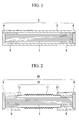
- FIG. 1 is a cross-sectional view showing an optical fiber bundle unit for transmitting ultraviolet light according to one embodiment of the present invention.
- FIG. 2 is a cross-sectional view showing an optical fiber bundle unit for transmitting ultraviolet light according to another embodiment of the present invention.
- FIG. 1 is a cross-sectional view showing an optical fiber bundle unit for transmitting ultraviolet light according to one embodiment of the present invention.
- the optical fiber bundle unit for transmitting ultraviolet light includes an optical fiber bundle 1, a sealed container 2 holding the optical fiber bundle 1, and stopper members 5 and 5 fastening the optical fiber bundle 1 to both ends of the sealed container 2.
- the optical fiber bundle 1 includes a plurality of pure quartz glass core optical fibers each having a pure quartz glass core portion and a cladding portion doped with fluorine, which are bundled together.
- the optical fiber bundle unit for transmitting ultraviolet light the optical fiber bundle 1 is fastened to the both ends of the sealed container 2 by the stopper members 5 and 5 and is held in the sealed container 2.
- the stopper member 5 is preferably produced from metal such as stainless steel, brass, aluminum, or the like, or ceramic such as alumina ceramic, quartz, or the like.
- the optical fiber bundle 1 is preferably pretreated in the hydrogen atmosphere in which the pressure is set to 1 to 500 kgf/cm 2 , more preferably 10 to 100 kgf/cm 2 , and the temperature is set to 80 to 300°C, more preferably 100 to 150°C.
- the optical fiber bundle 1 is exposed to hydrogen under the conditions in which the pressure is set to 1 to 500 kgf/cm 2 and the temperature is set to 80 to 300°C, hydrogen efficiently enters and diffuses into the optical fibers of the optical fiber bundle 1.
- the optical fiber bundle 1 is put in the sealed container 2 and hydrogen gas is filled in the sealed container 2. Thereby, even when radicals are generated in the optical fiber bundle 1, hydrogen can immediately react with the radicals, as a result of which the energy state of the optical fiber bundle 1 can be maintained to be stable.
- the sealed container 2 includes a cylindrical member 3 and tabular sealing members 4 and 4 which seal both ends of the cylindrical member 3.
- the optical fiber bundle 1 is held and hydrogen gas is filled up to a predetermined pressure, preferably 1 to 500 kgf/cm 2 , and more preferably 10 to 100 kgf/cm 2 .
- the cylindrical member 3 is produced from a material through which hydrogen cannot permeate or barely permeates, such as a metal such as stainless steel or the like.
- the cylindrical member 3 is flexible.
- the cylindrical member 3 is preferably produced from a metal pipe, a metal corrugated pipe, or the like, such as a accordion pleated copper, an accordion pleated stainless steel, or the like, which is flexibly worked so as to have a structure in which the cross-sectional shape in the longitudinal direction is in a wavy shape and the external shape is a frilled shape.
- the optical fiber bundle unit for transmitting ultraviolet light can be laid at various locations and can be broadly applied for various purposes.
- the thickness of the cylindrical member 3 is determined in compliance with the material thereof.
- the thickness of the cylindrical member 3 is preferably 50 to 1,000 ⁇ m, and more preferably 100 to 500 ⁇ m.
- the length of the cylindrical member 3 can preferably be adjustable in the longitudinal direction.
- the cylindrical member 3 is preferably flexibly worked so as to have a structure in which the cross-sectional shape in the longitudinal direction is a wavy shape and the external shape is a frilled shape.
- an adjusting member for adjusting the length of the cylindrical member 3 to the length of the optical fiber bundle 1 may be disposed at the cylindrical member 3.
- This adjusting member comprises, for example, a tube member and a sleeve which is inserted into the tube member so as to slidably move along the longitudinal direction of the tube member.
- the adjusting member is disposed at the cylindrical member 3 so as to possess the same axis with the cylindrical member 3 and to connect the tube member or sleeve with the end of the cylindrical member 3, and the length of the cylindrical member 3 can be adjusted by moving the sleeve.
- the tube member and the sleeve are airtightly joined by an airtight joint or a seal using a technique such as adhesion, welding, or caulking after moving the sleeve, for example.
- the adjusting member can also be disposed at the midway of the cylindrical member 3.
- the length of the cylindrical member 3 When the length of the cylindrical member 3 is adjustable in the longitudinal direction, the length of the cylindrical member 3 can be adjusted in accordance with the length of the optical fiber bundle 1 held in the cylindrical member 3, as a result of which both ends of the optical fiber bundle 1 can be adapted to inner surfaces of sealing members 4 and 4 disposed at both ends of the cylindrical member 3. Thereby, the loss increase of light which is incident on one end of the optical fiber bundle 1 through one of the sealing members 4 and 4 and which is emitted from the other end of the optical fiber bundle 1 through the other of the sealing members 4 and 4 can be suppressed.
- the sealing member 4 is produced from a light-transmitting material, preferably from a material which can transmit a high proportion of ultraviolet light, such as magnesium fluoride, quartz glass, or the like, in order that light can efficiently enter the optical fiber bundle 1 held in the sealed container 2.
- a material which can transmit a high proportion of ultraviolet light such as magnesium fluoride, quartz glass, or the like
- the sealing member 4 is preferably exposed to hydrogen in the same manner as the optical fiber bundle 1 described above so as to eliminate radicals generated in the sealing member 4.
- an AR (anti reflect) coating is performed on the sealing member 4.
- the sealing member 4 has a strength which can resist the pressure of the gas filled up in the sealed container 2.
- the thickness of the sealing member 4 is determined in compliance with factors such as an effective diameter of the sealing member 4 and a safety factor required to the effective diameter which is estimated at 3 - 10 times and more, for example.
- seals are formed between the sealing members 4 and 4 and the cylindrical member 3 by using a sealant such as an O-ring, various adhesives, an indium wire, or the like, or by brazing.
- a sealant such as an O-ring, various adhesives, an indium wire, or the like, or by brazing.
- a suitable sealing material such as glasses such as low temperature melt glass, resins, metals, or the like may be filled between the optical fibers of the optical fiber bundle 1 or between the optical fiber bundle 1 and the sealed container 2, so as to improve the air tightness therebetween.
- the air tightness can also be improved by performing fusion welding of a plurality of pure quartz glass core optical fibers of the optical fiber bundle 1.
- the inside of the sealed container 2 has an improved sealed structure.
- the sealing members 4 and 4 may not be disposed in the sealed container 2 and both ends of the optical fiber bundle 1 may be bare.
- the both ends of the optical fiber bundle 1 can be bare, the loss of ultraviolet light incident on optical fiber bundle 1 can be suppressed because ultraviolet light is not blocked off by the sealing member 4.
- the concentration and the pressure of the hydrogen gas filled in the sealed container 2 together with the optical fiber bundle 1 is set to be high, in order to improve optical properties and durability by sufficiently eliminating radicals generated in the optical fiber bundle 1.
- the hydrogen gas is preferably one component of a mixed gas including the hydrogen gas and a gas which is not combustible, will not support combustion, and will not explode, in order to ensure safety when the sealed container 2 is broken. By mixing the gas which is not combustible, will not support combustion, and will not explode with the hydrogen gas, an explosion can be prevented even when the gas filled in the sealed container 2 leaks from the sealed container 2.
- gas which is not combustible will not support combustion, and will not explode include rare gases such as helium (He) gas, neon (Ne) gas, and argon (Ar) gas, nitrogen (N 2 ) gas, carbon dioxide (CO 2 ) gas, mixed gases thereof, and the like.
- rare gases such as helium (He) gas, neon (Ne) gas, and argon (Ar) gas, nitrogen (N 2 ) gas, carbon dioxide (CO 2 ) gas, mixed gases thereof, and the like.
- the pressure of the hydrogen gas can also be increased.
- the concentration of the hydrogen gas is suitably determined so as to improve optical properties and durability and not to cause explosions.
- the concentration of the hydrogen gas is preferably 4% and below by volume, and more preferably 1 to 3.5 % by volume, relative to the total volume of the mixed gas. When the concentration of the hydrogen gas is over 4% by volume (in the atmosphere), the risk of generating an explosion may tend to increase when the gas leaks from the sealed container 2.
- the pressure of the hydrogen gas is also determined preferably 1 to 500 kgf/cm 2 , and more preferably 10 to 100 kgf/cm 2 , for example, so as to improve optical properties and durability.
- the pressure of the hydrogen gas is preferably 1 times atmospheric pressure or less, more preferably 0.01 to 1 atmospheric pressure for considering the safety.
- the molecular size of the gas which is not combustible, will not support combustion, and will not explode is preferably larger than the size of an aperture portion formed in a net-like molecular structure of the quartz glass included in the optical fiber bundle 1.
- the molecular size of the gas which is not combustible, will not support combustion, and will not explode is preferably 1.5 angstrom and more, more preferably 2 to 10 angstrom.
- the gas contained in the mixed gas in addition to the hydrogen gas can prevent the hydrogen gas from diffusing from the optical fiber bundle 1.
- the concentration of the hydrogen gas kept in the optical fiber bundle 1 can be increased without increasing the concentration of the hydrogen gas in the sealed container 2.
- the pressure of the mixed gas can be suitably determined in accordance with the size of the sealed container 2 or the like, the pressure of the mixed gas is preferably within a range from 1 to 500 kgf/cm 2 , and more preferably 10 to 100 kgf/cm 2 , for example.
- the concentration of the hydrogen gas in the optical fiber bundle 1 can be maintained to a predetermined level by mixing the hydrogen gas with appropriate rare gas of which the molecular size is sufficiently smaller than that of the aperture portion in the net-like molecular structure of the quartz glass of the optical fibers and which does not substantially influence optical characteristics of the optical fibers of the optical fiber bundle 1.
- the optical fiber bundle 1 pretreated by the hydrogen gas is inserted into the sealed container 2, followed by filling the sealed container 2 with air or the gas in addition to the hydrogen gas at 0.5 to 100 atmospheric pressure, more preferably at 10 to 100 atmospheric pressure, as a result of which the diffusion of the hydrogen gas can be prevented.
- the sealed container 2 In order to fill the gas into the sealed container 2, the sealed container 2 is sealed in the gas atmosphere by means of the sealing members 4 and 4.
- the gas may be filled into the sealed container 2 through a valve provided with a check valve, which is disposed at at least one of the sealing members 4 and 4.
- a check valve By using the valve provided with the check valve, it is possible to prevent the leakage of the mixed gas during filling of the gas into the sealed container 2.
- FIG. 2 is a cross-sectional view showing another embodiment of the optical fiber bundle unit for transmitting ultraviolet light according to the present invention.
- This optical fiber bundle unit for transmitting ultraviolet light is different from the optical fiber bundle unit for transmitting ultraviolet light shown in FIG. 1 in that a cylindrical member 10 included in a sealed container 20 includes a flexible member 11 and fixing members 12 and 12.
- the flexible member 11 has flexibility and is produced from a metal pipe such as a stainless steel pipe flexibly worked to have an accordion pleated structure in which the cross-sectional shape in the longitudinal direction is a wavy shape and the external shape is a frilled shape.
- the aforementioned optical fiber bundle unit can be applied for transmitting the light under the radial rays such as ⁇ -rays in addition to ultraviolet light without increasing the transmission loss of the optical fiber bundle. Moreover, even when the optical fiber bundle unit is used for transmitting intense ultraviolet light such those from as an excimer laser, the optical transmittance and the durability of the optical fiber bundle scarcely decrease.
- the optical fiber bundle unit for transmitting ultraviolet light includes the optical fiber bundle and the sealed container holding the optical fiber bundle and the hydrogen gas, radicals generated by irradiating or transmitting ultraviolet light into the optical fiber bundle can be eliminated by reaction between hydrogen and radicals, as a result of which the energy state of the optical fiber bundle can be maintained so as to be stable, and the increase of the transmission loss can be suppressed.
- the optical fiber bundle is pretreated in the hydrogen atmosphere in which the pressure is set to 1 to 500 kgf/cm 2 and the temperature is set to 80 to 300°C, even when radicals are generated in the optical fibers of the optical fiber bundle, the radicals are more effectively eliminated by immediately reacting with the hydrogen gas and the energy state is recovered so as to be stable.
- the optical fiber bundle unit can be layed on various places.
- the sealing members produced from the light-transmittable material are formed at the both ends of the sealed container, the loss increase of light incident on the optical fiber bundle can be emitted therefrom.
- the length of the sealed container can be adjusted in accordance with the length of the optical fiber bundle held in the sealed container, as a result of which both ends of the optical fiber bundle can appropriately be adapted to the inner surfaces of the sealing members at both ends of the sealed container.
- the hydrogen gas is one component of the mixed gas filled into the sealed container and including the gas which is not combustible, will not support combustion, and will not explode, the safety of the optical fiber bundle unit can be increased even when the gas leaks out from the sealed container.
- the pressure of the hydrogen gas contained in the sealed container is 1 times atmospheric pressure or less, the hydrogen gas is pushed back into the sealed container by atmospheric pressure even when the air tightness of the sealed container is lost by breaking the sealed container. As a result, the safety of the optical fiber bundle unit can be increased.
- the molecular size of the gas which is not combustible, will not support combustion, and will not explode is larger than the size of the aperture portion formed in a net-like molecular structure of the quartz glass, the gas except for the hydrogen gas cannot significantly penetrate into the optical fiber bundle and the hydrogen gas can mostly penetrate into the optical fiber bundle, as a result of which the optical fiber bundle is scarcely influenced by the gas except for the hydrogen gas.
Landscapes
- Physics & Mathematics (AREA)
- General Physics & Mathematics (AREA)
- Optics & Photonics (AREA)
- Health & Medical Sciences (AREA)
- Toxicology (AREA)
- Optical Fibers, Optical Fiber Cores, And Optical Fiber Bundles (AREA)
Abstract
Description
Claims (9)
- An optical fiber bundle unit for transmitting ultraviolet light including:wherein the sealed container contains a hydrogen gas.an optical fiber bundle; anda sealed container in which the optical fiber bundle is held,
- An optical fiber bundle unit for transmitting ultraviolet light according to claim 1,
wherein the optical fiber bundle is pretreated in a hydrogen atmosphere in which the pressure is set to 1 to 500 kgf/cm2 and the temperature is set to 80 to 300°C. - An optical fiber bundle unit for transmitting ultraviolet light according to claim 1,
wherein the sealed container is flexible. - An optical fiber bundle unit for transmitting ultraviolet light according to claim 1,
wherein sealing members produced from a light-transmittable material are formed at both ends of the sealed container. - An optical fiber bundle unit for transmitting ultraviolet light according to claim 1,
wherein the length of the sealed container is adjustable in the longitudinal direction. - An optical fiber bundle unit for transmitting ultraviolet light according to claim 1,
wherein the sealed container contains a mixed gas including the hydrogen gas and a gas which is not combustible, will not support combustion, and will not explode. - An optical fiber bundle unit for transmitting ultraviolet light according to claim 1,
wherein the pressure of the hydrogen gas contained in the sealed container is set to a pressure of 1 atmosphere or less. - An optical fiber bundle unit for transmitting ultraviolet light according to claim 1,
wherein the molecular size of the gas which is not combustible, will not support combustion, and will not explode is larger than the size of an aperture portion formed in a net-like molecular structure of a quartz glass included in the optical fiber bundle. - An optical fiber bundle unit for transmitting ultraviolet light including:wherein a diffusion of hydrogen gas is suppressed by putting the optical fiber bundle pretreated in a hydrogen atmosphere into the sealed container, followed by filling the sealed container with a gas which is not combustible, will not support combustion, and will not explode.an optical fiber bundle; anda sealed container in which the optical fiber bundle is held,
Applications Claiming Priority (2)
| Application Number | Priority Date | Filing Date | Title |
|---|---|---|---|
| JP2001149953 | 2001-05-18 | ||
| JP2001149953 | 2001-05-18 |
Publications (3)
| Publication Number | Publication Date |
|---|---|
| EP1258754A2 true EP1258754A2 (en) | 2002-11-20 |
| EP1258754A3 EP1258754A3 (en) | 2004-07-14 |
| EP1258754B1 EP1258754B1 (en) | 2006-10-04 |
Family
ID=18995057
Family Applications (1)
| Application Number | Title | Priority Date | Filing Date |
|---|---|---|---|
| EP02008000A Expired - Lifetime EP1258754B1 (en) | 2001-05-18 | 2002-04-10 | Optical fiber bundle unit for transmitting ultraviolet light |
Country Status (3)
| Country | Link |
|---|---|
| US (2) | US6892012B2 (en) |
| EP (1) | EP1258754B1 (en) |
| DE (1) | DE60215072T2 (en) |
Cited By (2)
| Publication number | Priority date | Publication date | Assignee | Title |
|---|---|---|---|---|
| WO2003098291A1 (en) * | 2002-05-17 | 2003-11-27 | Sumitomo Electric Industries, Ltd. | Optical fiber bundle and method for manufacture thereof |
| EP4621454A1 (en) * | 2024-03-20 | 2025-09-24 | Technische Universität Dresden, Körperschaft des öffentlichen Rechts | Method for compensating the difference in propagation time of optical waveguides |
Families Citing this family (1)
| Publication number | Priority date | Publication date | Assignee | Title |
|---|---|---|---|---|
| JP7167223B2 (en) * | 2021-03-19 | 2022-11-08 | 日立建機株式会社 | hydraulic system |
Family Cites Families (30)
| Publication number | Priority date | Publication date | Assignee | Title |
|---|---|---|---|---|
| US3279902A (en) * | 1963-07-11 | 1966-10-18 | William L Gardner | Fluid tight sealing of glass fiber devices |
| JPS61210302A (en) | 1985-03-14 | 1986-09-18 | Furukawa Electric Co Ltd:The | Radiation resistant optical transmission body |
| JPS6214604A (en) | 1985-07-12 | 1987-01-23 | Furukawa Electric Co Ltd:The | Radiation-resisting fiber scope |
| JPS6214602A (en) | 1985-07-12 | 1987-01-23 | Stanley Electric Co Ltd | Preparation of color filter |
| GB8519426D0 (en) | 1985-08-01 | 1985-09-04 | Ici Plc | Composition for personal care products |
| US4792347A (en) * | 1986-09-25 | 1988-12-20 | Corning Glass Works | Method for coating optical waveguide fiber |
| JPS63129034A (en) | 1986-11-14 | 1988-06-01 | Fujikura Ltd | Treatment of optical fiber |
| FR2641616B1 (en) | 1989-01-12 | 1993-07-09 | Thomson Csf | FIBER OPTIC DEVICE AND ITS PROTECTIVE SHEATH |
| US5059229A (en) * | 1990-09-24 | 1991-10-22 | Corning Incorporated | Method for producing optical fiber in a hydrogen atmosphere to prevent attenuation |
| US5061035A (en) * | 1990-09-27 | 1991-10-29 | Hughes Aircraft Company | Hermetically sealed optical fiber arrays and method for forming same |
| US5203896A (en) * | 1992-04-02 | 1993-04-20 | Ceramoptec, Inc. | Process for producing hard plastic clad optical fiber with improved ultraviolet transmission |
| JPH0634830A (en) | 1992-07-21 | 1994-02-10 | Fujikura Ltd | Fiber for ultraviolet ray transmission |
| US5267343A (en) * | 1992-09-03 | 1993-11-30 | The United States Of America As Represented By The United States Department Of Energy | Enhanced radiation resistant fiber optics |
| JPH06277227A (en) * | 1993-03-26 | 1994-10-04 | Toshiba Medical Eng Co Ltd | Laser medical treatment device |
| JPH0894871A (en) | 1994-07-29 | 1996-04-12 | Bridgestone Corp | Light transmission tube |
| US5657404A (en) * | 1995-05-25 | 1997-08-12 | Eastman Chemical Company | Robust spectroscopic optical probe |
| JPH09171118A (en) | 1995-12-20 | 1997-06-30 | Bridgestone Corp | Optical transmission tube protection structure |
| EP0780707A1 (en) * | 1995-12-21 | 1997-06-25 | Heraeus Quarzglas GmbH | Element for UV high energy radiation transmission and method of fabrication of such an element and its utilisation |
| US6333283B1 (en) * | 1997-05-16 | 2001-12-25 | Sumitomo Electric Industries, Ltd. | Silica glass article and manufacturing process therefor |
| JP2000203856A (en) | 1999-01-12 | 2000-07-25 | Sumitomo Electric Ind Ltd | Quartz glass article and method for producing the same |
| JP2980094B2 (en) | 1997-05-16 | 1999-11-22 | 住友電気工業株式会社 | Quartz glass article and method for producing the same |
| JP3456449B2 (en) | 1997-05-16 | 2003-10-14 | 住友電気工業株式会社 | Quartz glass article and method for producing the same |
| US5901264A (en) * | 1997-06-12 | 1999-05-04 | Fiberguide Industries | Solar resistant optical fiber and method |
| US6130981A (en) | 1998-03-20 | 2000-10-10 | Polymicro Technologies, Llc | Gamma radiation sterilized fiber optic UV delivery systems |
| JP2000321445A (en) | 1999-05-10 | 2000-11-24 | Kitagawa Ind Co Ltd | Optical fiber equipment |
| JP2000086273A (en) | 1998-09-14 | 2000-03-28 | Fujikura Ltd | Manufacturing method of optical fiber for ultraviolet transmission |
| US6188814B1 (en) * | 1999-08-03 | 2001-02-13 | Lucent Technologies Inc. | Packaged microelectromechanical devices and systems |
| US6587625B1 (en) * | 2000-02-15 | 2003-07-01 | Lucent Technologies Inc. | Optical fiber apparatus for high-radiation environments |
| US6496627B1 (en) * | 2000-07-14 | 2002-12-17 | Tyco Telecommunications (Us) Inc. | Device and method for improved long term signal attenuation performance of fiber optic cable and apparatus interfaces |
| JP3995000B2 (en) * | 2002-05-17 | 2007-10-24 | 住友電気工業株式会社 | Optical fiber bundle and manufacturing method thereof |
-
2002
- 2002-04-09 US US10/119,916 patent/US6892012B2/en not_active Expired - Fee Related
- 2002-04-10 DE DE60215072T patent/DE60215072T2/en not_active Expired - Lifetime
- 2002-04-10 EP EP02008000A patent/EP1258754B1/en not_active Expired - Lifetime
-
2005
- 2005-03-17 US US11/084,515 patent/US7813607B2/en not_active Expired - Fee Related
Cited By (3)
| Publication number | Priority date | Publication date | Assignee | Title |
|---|---|---|---|---|
| WO2003098291A1 (en) * | 2002-05-17 | 2003-11-27 | Sumitomo Electric Industries, Ltd. | Optical fiber bundle and method for manufacture thereof |
| US7277616B2 (en) | 2002-05-17 | 2007-10-02 | Sumitomo Electric Industries, Ltd. | Optical fiber bundle and method of manufacturing the same |
| EP4621454A1 (en) * | 2024-03-20 | 2025-09-24 | Technische Universität Dresden, Körperschaft des öffentlichen Rechts | Method for compensating the difference in propagation time of optical waveguides |
Also Published As
| Publication number | Publication date |
|---|---|
| EP1258754A3 (en) | 2004-07-14 |
| US6892012B2 (en) | 2005-05-10 |
| US7813607B2 (en) | 2010-10-12 |
| DE60215072T2 (en) | 2007-04-05 |
| EP1258754B1 (en) | 2006-10-04 |
| US20050238302A1 (en) | 2005-10-27 |
| DE60215072D1 (en) | 2006-11-16 |
| US20020172479A1 (en) | 2002-11-21 |
Similar Documents
| Publication | Publication Date | Title |
|---|---|---|
| US5223014A (en) | Method for splicing and reinforcing carbon coated optical fibers | |
| JPH1129335A (en) | Quartz glass article and method for producing the same | |
| JP2000203856A (en) | Quartz glass article and method for producing the same | |
| US20090238215A1 (en) | Method Of Inducing Refractive Index Structures In A Micro-Structured Fiber, A Micro-Structured Fiber And An Article | |
| WO2005003827A1 (en) | Optical fiber, optical fiber connecting method, and optical connector | |
| US6892012B2 (en) | Optical fiber bundle unit for transmitting ultraviolet light | |
| NO953751L (en) | Manufacture of optical cable with metal or steel pipe casing | |
| US5664040A (en) | Fiber optic assembly and method of making same | |
| CA2541735C (en) | Conditioning optical fibers for improved ionizing radiation response | |
| US20080190146A1 (en) | Optical fiber bundle and method of manufacture the same | |
| US6661957B1 (en) | Diffusion barriers for holey fibers | |
| GB1575134A (en) | Fibre-optic cable | |
| JP2003035829A (en) | Optical fiber bundle for ultraviolet transmission | |
| EP1394128B1 (en) | Optical apparatus | |
| EP0950032B1 (en) | Apparatus and method for reducing break sources in drawn fibers | |
| CN1802577A (en) | Method and apparatus for the photosensitization of optical fiber | |
| EP0773195A1 (en) | Glass body for optical fiber, use thereof, optical fiber, and method of making it | |
| JP2003021731A (en) | Bundle fiber for ultraviolet light transmission | |
| JP2007272251A (en) | Fiber optic bundle | |
| JP4008116B2 (en) | Manufacturing method of optical fiber for ultraviolet transmission | |
| US6587625B1 (en) | Optical fiber apparatus for high-radiation environments | |
| JPH02220003A (en) | Optical fiber cable | |
| JPH04347805A (en) | Fusion-splicing connection method for carbon-coated optical fiber | |
| JPH05246740A (en) | Method for recoating carbon film on exposed silica fiber of carbon-coated optical fiber | |
| JPH05246741A (en) | Carbon coated optical fiber recoating method |
Legal Events
| Date | Code | Title | Description |
|---|---|---|---|
| PUAI | Public reference made under article 153(3) epc to a published international application that has entered the european phase |
Free format text: ORIGINAL CODE: 0009012 |
|
| AK | Designated contracting states |
Kind code of ref document: A2 Designated state(s): AT BE CH CY DE DK ES FI FR GB GR IE IT LI LU MC NL PT SE TR |
|
| AX | Request for extension of the european patent |
Free format text: AL;LT;LV;MK;RO;SI |
|
| PUAL | Search report despatched |
Free format text: ORIGINAL CODE: 0009013 |
|
| AK | Designated contracting states |
Kind code of ref document: A3 Designated state(s): AT BE CH CY DE DK ES FI FR GB GR IE IT LI LU MC NL PT SE TR |
|
| AX | Request for extension of the european patent |
Extension state: AL LT LV MK RO SI |
|
| RIC1 | Information provided on ipc code assigned before grant |
Ipc: 7G 02B 6/16 A Ipc: 7G 02B 6/36 B Ipc: 7G 02B 6/40 B |
|
| 17P | Request for examination filed |
Effective date: 20041216 |
|
| AKX | Designation fees paid |
Designated state(s): DE NL |
|
| 17Q | First examination report despatched |
Effective date: 20050405 |
|
| GRAP | Despatch of communication of intention to grant a patent |
Free format text: ORIGINAL CODE: EPIDOSNIGR1 |
|
| RIC1 | Information provided on ipc code assigned before grant |
Ipc: G02B 6/06 20060101ALI20060419BHEP Ipc: G02B 6/44 20060101AFI20060419BHEP |
|
| GRAS | Grant fee paid |
Free format text: ORIGINAL CODE: EPIDOSNIGR3 |
|
| GRAA | (expected) grant |
Free format text: ORIGINAL CODE: 0009210 |
|
| AK | Designated contracting states |
Kind code of ref document: B1 Designated state(s): DE NL |
|
| REF | Corresponds to: |
Ref document number: 60215072 Country of ref document: DE Date of ref document: 20061116 Kind code of ref document: P |
|
| PLBE | No opposition filed within time limit |
Free format text: ORIGINAL CODE: 0009261 |
|
| STAA | Information on the status of an ep patent application or granted ep patent |
Free format text: STATUS: NO OPPOSITION FILED WITHIN TIME LIMIT |
|
| 26N | No opposition filed |
Effective date: 20070705 |
|
| PGFP | Annual fee paid to national office [announced via postgrant information from national office to epo] |
Ref country code: DE Payment date: 20140430 Year of fee payment: 13 Ref country code: NL Payment date: 20140308 Year of fee payment: 13 |
|
| REG | Reference to a national code |
Ref country code: DE Ref legal event code: R119 Ref document number: 60215072 Country of ref document: DE |
|
| REG | Reference to a national code |
Ref country code: NL Ref legal event code: MM Effective date: 20150501 |
|
| PG25 | Lapsed in a contracting state [announced via postgrant information from national office to epo] |
Ref country code: DE Free format text: LAPSE BECAUSE OF NON-PAYMENT OF DUE FEES Effective date: 20151103 |
|
| PG25 | Lapsed in a contracting state [announced via postgrant information from national office to epo] |
Ref country code: NL Free format text: LAPSE BECAUSE OF NON-PAYMENT OF DUE FEES Effective date: 20150501 |