EP1258583A1 - Door unlocking system for vehicles - Google Patents
Door unlocking system for vehicles Download PDFInfo
- Publication number
- EP1258583A1 EP1258583A1 EP20010120200 EP01120200A EP1258583A1 EP 1258583 A1 EP1258583 A1 EP 1258583A1 EP 20010120200 EP20010120200 EP 20010120200 EP 01120200 A EP01120200 A EP 01120200A EP 1258583 A1 EP1258583 A1 EP 1258583A1
- Authority
- EP
- European Patent Office
- Prior art keywords
- key
- switch
- link
- door
- driver
- Prior art date
- Legal status (The legal status is an assumption and is not a legal conclusion. Google has not performed a legal analysis and makes no representation as to the accuracy of the status listed.)
- Withdrawn
Links
Images

Classifications
-
- E—FIXED CONSTRUCTIONS
- E05—LOCKS; KEYS; WINDOW OR DOOR FITTINGS; SAFES
- E05B—LOCKS; ACCESSORIES THEREFOR; HANDCUFFS
- E05B85/00—Details of vehicle locks not provided for in groups E05B77/00 - E05B83/00
-
- E—FIXED CONSTRUCTIONS
- E05—LOCKS; KEYS; WINDOW OR DOOR FITTINGS; SAFES
- E05B—LOCKS; ACCESSORIES THEREFOR; HANDCUFFS
- E05B77/00—Vehicle locks characterised by special functions or purposes
- E05B77/46—Locking several wings simultaneously
- E05B77/48—Locking several wings simultaneously by electrical means
-
- E—FIXED CONSTRUCTIONS
- E05—LOCKS; KEYS; WINDOW OR DOOR FITTINGS; SAFES
- E05B—LOCKS; ACCESSORIES THEREFOR; HANDCUFFS
- E05B81/00—Power-actuated vehicle locks
- E05B81/54—Electrical circuits
-
- Y—GENERAL TAGGING OF NEW TECHNOLOGICAL DEVELOPMENTS; GENERAL TAGGING OF CROSS-SECTIONAL TECHNOLOGIES SPANNING OVER SEVERAL SECTIONS OF THE IPC; TECHNICAL SUBJECTS COVERED BY FORMER USPC CROSS-REFERENCE ART COLLECTIONS [XRACs] AND DIGESTS
- Y10—TECHNICAL SUBJECTS COVERED BY FORMER USPC
- Y10S—TECHNICAL SUBJECTS COVERED BY FORMER USPC CROSS-REFERENCE ART COLLECTIONS [XRACs] AND DIGESTS
- Y10S292/00—Closure fasteners
- Y10S292/25—Remote control
-
- Y—GENERAL TAGGING OF NEW TECHNOLOGICAL DEVELOPMENTS; GENERAL TAGGING OF CROSS-SECTIONAL TECHNOLOGIES SPANNING OVER SEVERAL SECTIONS OF THE IPC; TECHNICAL SUBJECTS COVERED BY FORMER USPC CROSS-REFERENCE ART COLLECTIONS [XRACs] AND DIGESTS
- Y10—TECHNICAL SUBJECTS COVERED BY FORMER USPC
- Y10T—TECHNICAL SUBJECTS COVERED BY FORMER US CLASSIFICATION
- Y10T70/00—Locks
- Y10T70/50—Special application
- Y10T70/5889—For automotive vehicles
- Y10T70/5894—Plural point
- Y10T70/5898—With switch
-
- Y—GENERAL TAGGING OF NEW TECHNOLOGICAL DEVELOPMENTS; GENERAL TAGGING OF CROSS-SECTIONAL TECHNOLOGIES SPANNING OVER SEVERAL SECTIONS OF THE IPC; TECHNICAL SUBJECTS COVERED BY FORMER USPC CROSS-REFERENCE ART COLLECTIONS [XRACs] AND DIGESTS
- Y10—TECHNICAL SUBJECTS COVERED BY FORMER USPC
- Y10T—TECHNICAL SUBJECTS COVERED BY FORMER US CLASSIFICATION
- Y10T70/00—Locks
- Y10T70/50—Special application
- Y10T70/5889—For automotive vehicles
- Y10T70/5969—Other element with switch
-
- Y—GENERAL TAGGING OF NEW TECHNOLOGICAL DEVELOPMENTS; GENERAL TAGGING OF CROSS-SECTIONAL TECHNOLOGIES SPANNING OVER SEVERAL SECTIONS OF THE IPC; TECHNICAL SUBJECTS COVERED BY FORMER USPC CROSS-REFERENCE ART COLLECTIONS [XRACs] AND DIGESTS
- Y10—TECHNICAL SUBJECTS COVERED BY FORMER USPC
- Y10T—TECHNICAL SUBJECTS COVERED BY FORMER US CLASSIFICATION
- Y10T70/00—Locks
- Y10T70/60—Systems
- Y10T70/625—Operation and control
- Y10T70/65—Central control
Definitions
- This invention relates to a door unlocking system of vehicles, and more particularly, to the door unlocking system in which a switch for simultaneously unlocking the front and rear doors is installed regardless of a door chassis and a key rotor.
- the driver's door includes a switch for transmitting a signal to a central processing unit, wherein the driver inserts the key into the key box and turns the key to one direction to simultaneously unlock the front door and rear door while the driver turns the key inserted in the key box to the other direction to simultaneously lock the front door and rear door.
- FIG. 1 shows installation of the switch rearward the key box 20, which is disadvantageous in that the narrow space between a door chassis and a key rotor does not allows the switch 10 be installed rearward the key box 20.
- a door unlocking system for unlocking the front and rear doors by outputting to the central processing unit from the switch in the directions from the neutral position of the key inserted into the key box, in which the switch is installed at the door latch for unlocking the driver's door, and the switch transmits the signal to the central processing unit according to the signal input in the key rod clip to unlock the other doors.
- the key rod clip and the switch are connected by a key rod link, link and a switch link.
- the key rod link is connected to the key rod clip at one end, the link is connected to the key rod link at the other end, and switch link is connected to the link 34 and the switch, respectively.
- the door unlocking system of the present invention adopts the conventional switch 10 transmitting the signal to the central processing unit, dependent on the activating direction of the ignition key inserted in the key box, to unlock the front and rear doors.
- the switch 10 is installed at the door latch 30 for unlocking the driver's seat door and transmits the signal to the central processing unit according to the signal input in the key rod clip 31, to unlock the other doors.
- the key rod clip 31 and the switch 10 are connected by a key rod link 32, link 34 and a switch link 33.
- the key rod link 32 is connected to the key rod clip 31 at one end
- the link 34 is connected to the key rod link 32 at the other end
- switch link 33 is connected to the link 34 and the switch 10, respectively.
- the rotation force of the key is transmitted to the key rod clip 31.
- the rotation force of the key transmitted to the key rod clip 31 allows the key rod link 32 to actuate.
- the actuating force of the key rod link is transmitted to the switch link 33 via the link 34.
- the switch link 33 After the switch link 33 receives the rotation force from the key, the switch transmits the signal to the central processing unit to unlock the front door and the rear door as well as the driver's door.
- the switch 10 is fixed at the door latch 30 and connected to the key rod link 32, link 34 and switch link 33, so that the switch 10 is installed regardless of the door chassis and the key rotor.
- the invention provides a door unlocking system with the switch 10 transmitting the signal to the central processing unit according to the rotary direction of the key inserted into the key box to unlock the front and rear doors, wherein the switch is installed at the door latch 30 unlocking the driver's door and the switch transmits the signal to the central processing unit according to the signal input in the key rod clip 31 to unlock the other doors, in the inserted status, the key turns to one direction to operate the switch, thereby installing the switch in the driver's door regardless of the door chassis and the key rotor.
- Fig. 1 With the axis of a key rotating, the axis of a switch 10 and connection portion are rotated to connect terminals formed at the switch fixing portion, thereby effecting on/off operation.
- the key rod Since the switch is integrally formed in the latch, the key rod functions to deliver actuation of the key to the latch by the switch. That is to say, when the key is turned in a predetermined direction, the key rod performs a rectilinear movement to rotate the link 32.
- the rotated link 32 enables the link 34 to perform a rectilinear movement and the link 34 to rotate a link 33, so that the switch contact connected to the link 32 connects the terminals formed at the switch fixing portion, thereby effecting on/off operation.
- Fig. 2 Since the key box is installed in the neighboring steering wheel, Fig. 2 does not show the key box.
- the turning actuation of the key is delivered by mechanical means to the key rod clip and the actuation is further delivered to the switch, thereby effecting the switch on/off according to the key actuation.
- the driver inserts the key into the key box and turns the inserted key. With the key rotating, the key axis and the bracket are rotated and the rotary movement is received by the key rod. Then the key rod performs a rectilinear movement to deliver the rotary movement to the link 32 and to rotate the link 32. The movement further leads the link 34 to rectilinear movement and the link 33 to rotary movement. Since the link 33 is connected to the switch 10, the switch contact becomes on/off in rotating the link 33.
- an electronic control unit unlocks only the driver's door to open.
- the electronic control unit unlocks all the doors of the vehicle to open.
Landscapes
- Lock And Its Accessories (AREA)
Abstract
The invention provides a door unlocking system with the switch (10)
transmitting the signal to the central processing unit according to the rotary
direction of the key inserted into the key box to unlock the front and rear doors,
wherein the switch is installed at the door latch (30) unlocking the driver's door an
d the switch transmits the signal to the central processing unit according to the sign
al input in the key rod clip (31) to unlock the other doors, in the inserted status, the
key turns to one direction to operate the switch, thereby installing the switch in the
driver's door regardless of the door chassis and the key rotor.
Description
- This invention relates to a door unlocking system of vehicles, and more particularly, to the door unlocking system in which a switch for simultaneously unlocking the front and rear doors is installed regardless of a door chassis and a key rotor.
- Generally, the driver's door includes a switch for transmitting a signal to a central processing unit, wherein the driver inserts the key into the key box and turns the key to one direction to simultaneously unlock the front door and rear door while the driver turns the key inserted in the key box to the other direction to simultaneously lock the front door and rear door.
- The prior art (Fig. 1) shows installation of the switch rearward the
key box 20, which is disadvantageous in that the narrow space between a door chassis and a key rotor does not allows theswitch 10 be installed rearward thekey box 20. - Accordingly, it is an object of the present invention to provide a door unlocking system for unlocking the front and rear doors by outputting to the central processing unit from the switch in the directions from the neutral position of the key inserted into the key box, in which the switch is installed at the door latch for unlocking the driver's door, and the switch transmits the signal to the central processing unit according to the signal input in the key rod clip to unlock the other doors. The key rod clip and the switch are connected by a key rod link, link and a switch link. The key rod link is connected to the key rod clip at one end, the link is connected to the key rod link at the other end, and switch link is connected to the
link 34 and the switch, respectively. - The present invention will become more fully understood from the detailed description given hereinbelow and the accompanying drawings, which are given by way of illustration only, and thus, are not limitative of the present invention, and wherein:
- Fig. 1 is a sectional view showing the installation of the conventional switch; and
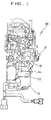
- Fig. 2 is a sectional view showing the installation according to the present invention.
-
- As shown in Fig. 2, the door unlocking system of the present invention adopts the
conventional switch 10 transmitting the signal to the central processing unit, dependent on the activating direction of the ignition key inserted in the key box, to unlock the front and rear doors. - In the present invention, however, the
switch 10 is installed at thedoor latch 30 for unlocking the driver's seat door and transmits the signal to the central processing unit according to the signal input in thekey rod clip 31, to unlock the other doors. - The
key rod clip 31 and theswitch 10 are connected by akey rod link 32,link 34 and aswitch link 33. Thekey rod link 32 is connected to thekey rod clip 31 at one end, thelink 34 is connected to thekey rod link 32 at the other end, andswitch link 33 is connected to thelink 34 and theswitch 10, respectively. - According to the present invention, when the driver in a car inserts the key into the key box and turns the key in one direction, the rotation force of the key is transmitted to the
key rod clip 31. The rotation force of the key transmitted to thekey rod clip 31 allows thekey rod link 32 to actuate. The actuating force of the key rod link is transmitted to theswitch link 33 via thelink 34. - After the
switch link 33 receives the rotation force from the key, the switch transmits the signal to the central processing unit to unlock the front door and the rear door as well as the driver's door. - Accordingly, the
switch 10 is fixed at thedoor latch 30 and connected to thekey rod link 32,link 34 andswitch link 33, so that theswitch 10 is installed regardless of the door chassis and the key rotor. - The present invention is not limited to these embodiments, and it should be clear to those skilled in the art that other embodiments are possible within the spirit and scope of the invention claimed.
- The invention provides a door unlocking system with the
switch 10 transmitting the signal to the central processing unit according to the rotary direction of the key inserted into the key box to unlock the front and rear doors, wherein the switch is installed at thedoor latch 30 unlocking the driver's door and the switch transmits the signal to the central processing unit according to the signal input in thekey rod clip 31 to unlock the other doors, in the inserted status, the key turns to one direction to operate the switch, thereby installing the switch in the driver's door regardless of the door chassis and the key rotor. - In Fig. 1: With the axis of a key rotating, the axis of a
switch 10 and connection portion are rotated to connect terminals formed at the switch fixing portion, thereby effecting on/off operation. - Regarding the key rod clip: Since the switch is integrally formed in the latch, the key rod functions to deliver actuation of the key to the latch by the switch. That is to say, when the key is turned in a predetermined direction, the key rod performs a rectilinear movement to rotate the
link 32. The rotatedlink 32 enables thelink 34 to perform a rectilinear movement and thelink 34 to rotate alink 33, so that the switch contact connected to thelink 32 connects the terminals formed at the switch fixing portion, thereby effecting on/off operation. - In Fig. 2: Since the key box is installed in the neighboring steering wheel, Fig. 2 does not show the key box. The turning actuation of the key is delivered by mechanical means to the key rod clip and the actuation is further delivered to the switch, thereby effecting the switch on/off according to the key actuation.
- The driver inserts the key into the key box and turns the inserted key. With the key rotating, the key axis and the bracket are rotated and the rotary movement is received by the key rod. Then the key rod performs a rectilinear movement to deliver the rotary movement to the
link 32 and to rotate thelink 32. The movement further leads thelink 34 to rectilinear movement and thelink 33 to rotary movement. Since thelink 33 is connected to theswitch 10, the switch contact becomes on/off in rotating thelink 33. - Therefore, when the driver rotates the key one time, an electronic control unit unlocks only the driver's door to open. When the driver rotates the rotated key one more time within three seconds, the electronic control unit unlocks all the doors of the vehicle to open.
Claims (2)
- A door unlocking system of vehicles for unlocking the front and rear doors by outputting to the central processing unit from the switch (10) in the directions from the neutral position of the key inserted into the key box, characterized in that the switch is installed at the door latch (30) for unlocking the driver's door, and the switch transmits the signal to the central processing unit according to the signal input in the key rod clip to unlock the other doors.
- A door unlocking system of vehicles as claimed in claim 1, characterized in that the key rod clip (31) and the switch are connected by a key rod link (32), link (34) and a switch link (34), whereby the key rod link (32) is connected to the key rod clip (31) at one end, the link (34) is connected to the key rod link (32) at the other end, and switch link (33) is connected to the link (34) and the switch (10), respectively.
Applications Claiming Priority (2)
| Application Number | Priority Date | Filing Date | Title |
|---|---|---|---|
| KR2001026760 | 2001-05-16 | ||
| KR10-2001-0026760A KR100394715B1 (en) | 2001-05-16 | 2001-05-16 | Door unlock system for vehicle |
Publications (1)
| Publication Number | Publication Date |
|---|---|
| EP1258583A1 true EP1258583A1 (en) | 2002-11-20 |
Family
ID=19709542
Family Applications (1)
| Application Number | Title | Priority Date | Filing Date |
|---|---|---|---|
| EP20010120200 Withdrawn EP1258583A1 (en) | 2001-05-16 | 2001-08-23 | Door unlocking system for vehicles |
Country Status (6)
| Country | Link |
|---|---|
| US (1) | US6598437B2 (en) |
| EP (1) | EP1258583A1 (en) |
| JP (1) | JP3586862B2 (en) |
| KR (1) | KR100394715B1 (en) |
| CN (1) | CN1205402C (en) |
| MY (1) | MY128291A (en) |
Families Citing this family (2)
| Publication number | Priority date | Publication date | Assignee | Title |
|---|---|---|---|---|
| DE102008059104B4 (en) * | 2008-11-26 | 2011-03-10 | Audi Ag | Method for controlling a locking system of a motor vehicle and motor vehicle |
| JP5727850B2 (en) * | 2011-04-22 | 2015-06-03 | 株式会社ユーシン | Door lock device |
Citations (3)
| Publication number | Priority date | Publication date | Assignee | Title |
|---|---|---|---|---|
| US4364249A (en) * | 1979-03-24 | 1982-12-21 | Kiekert Gmbh & Co. Kommanditgesellschaft | Central door-lock system for motor vehicles |
| US5005392A (en) * | 1989-06-22 | 1991-04-09 | Mitsui Kinzoku Kogyo Kabushiki Kaisha | Switch device in car lock device |
| EP0686745A2 (en) * | 1994-06-08 | 1995-12-13 | General Motors Corporation | Door latch with integral switch |
Family Cites Families (12)
| Publication number | Priority date | Publication date | Assignee | Title |
|---|---|---|---|---|
| DE3827564C2 (en) * | 1988-08-13 | 1993-12-23 | Daimler Benz Ag | Locking device for vehicles |
| DE4015522A1 (en) * | 1989-09-14 | 1991-03-28 | Bosch Gmbh Robert | DEVICE FOR LOCKING AND UNLOCKING CLOSED DOORS TO THE INTERIOR OF A MOTOR VEHICLE |
| DE4006122A1 (en) * | 1990-02-27 | 1991-08-29 | Daimler Benz Ag | METHOD FOR CONTROLLING A CENTRAL LOCKING SYSTEM AND A SECURING DEVICE FOR MOTOR VEHICLES, AND A CENTRAL LOCKING SYSTEM AND SECURING DEVICE |
| DE4008834C1 (en) * | 1990-03-20 | 1991-07-11 | Mercedes-Benz Aktiengesellschaft, 7000 Stuttgart, De | Interrogator for car door lock - has switch trip coupled to cylinder and connected to adjacent control switch |
| JP2614377B2 (en) | 1991-07-23 | 1997-05-28 | 株式会社東海理化電機製作所 | Door unlocking device |
| DE4222868A1 (en) * | 1992-07-11 | 1994-01-13 | Bosch Gmbh Robert | Locking device for doors of a motor vehicle |
| GB2285476B (en) * | 1994-01-11 | 1997-09-24 | Rockwell Body & Chassis Syst | Vehicle door lock actuator |
| DE19530720B4 (en) * | 1995-08-18 | 2004-07-22 | Kiekert Ag | central locking system |
| KR970028664A (en) * | 1995-11-23 | 1997-06-24 | 김태구 | Central locking device of the car |
| JPH1171950A (en) * | 1997-08-29 | 1999-03-16 | Honda Motor Co Ltd | Door lock device for automobile |
| US6072403A (en) | 1997-12-05 | 2000-06-06 | Kabushiki Kaisha Tokai Rika Denki Seisakusho | Door unlocking device for vehicle |
| KR20000020200U (en) * | 1999-04-30 | 2000-11-25 | 이관기 | Door switch assembly for vehicle |
-
2001
- 2001-05-16 KR KR10-2001-0026760A patent/KR100394715B1/en not_active Expired - Fee Related
- 2001-07-24 JP JP2001223598A patent/JP3586862B2/en not_active Expired - Fee Related
- 2001-08-02 MY MYPI20013657 patent/MY128291A/en unknown
- 2001-08-09 CN CNB011245867A patent/CN1205402C/en not_active Expired - Fee Related
- 2001-08-23 EP EP20010120200 patent/EP1258583A1/en not_active Withdrawn
- 2001-10-11 US US09/977,891 patent/US6598437B2/en not_active Expired - Fee Related
Patent Citations (3)
| Publication number | Priority date | Publication date | Assignee | Title |
|---|---|---|---|---|
| US4364249A (en) * | 1979-03-24 | 1982-12-21 | Kiekert Gmbh & Co. Kommanditgesellschaft | Central door-lock system for motor vehicles |
| US5005392A (en) * | 1989-06-22 | 1991-04-09 | Mitsui Kinzoku Kogyo Kabushiki Kaisha | Switch device in car lock device |
| EP0686745A2 (en) * | 1994-06-08 | 1995-12-13 | General Motors Corporation | Door latch with integral switch |
Also Published As
| Publication number | Publication date |
|---|---|
| JP2002349111A (en) | 2002-12-04 |
| US6598437B2 (en) | 2003-07-29 |
| MY128291A (en) | 2007-01-31 |
| JP3586862B2 (en) | 2004-11-10 |
| KR20020087760A (en) | 2002-11-23 |
| CN1385591A (en) | 2002-12-18 |
| CN1205402C (en) | 2005-06-08 |
| US20020170325A1 (en) | 2002-11-21 |
| KR100394715B1 (en) | 2003-08-14 |
Similar Documents
| Publication | Publication Date | Title |
|---|---|---|
| JP2550309B2 (en) | Unauthorized driving prevention device for automobile | |
| US20050179323A1 (en) | Remote start system for a vehicle having a data communications bus and related methods | |
| US20030150416A1 (en) | Remote start system including an engine speed data bus reader and related methods | |
| WO2003004810A2 (en) | Latch arrangement | |
| US20010022549A1 (en) | Motor vehicle door lock, motor vehicle door lock system and process for controlling a motor vehicle door lock | |
| US6225582B1 (en) | Steering column assembly | |
| CN101595005B (en) | Circuit of the electric actuation of the two-part tailgate for motor vehicles | |
| US6236004B1 (en) | Steering column assembly | |
| US20040244294A1 (en) | Drive | |
| US6467320B1 (en) | Door locking apparatus of automobile | |
| US6598437B2 (en) | Door unlocking system for vehicles | |
| JPH04228783A (en) | Central chain locking and safety devices for car, and controlling method therefor | |
| US6032496A (en) | Door lock arrangement for motor vehicles | |
| JP2006328690A (en) | Unlocking device | |
| NL2021839B1 (en) | Lock of the steering rod of a motor vehicle | |
| US5636879A (en) | Coupling structure between door lock and door lock-actuator | |
| JP2000054708A (en) | Door lock operating device | |
| KR100719748B1 (en) | Car starter | |
| KR102937394B1 (en) | Car door handles with built-in sensors | |
| JPH0512117Y2 (en) | ||
| CA2415038C (en) | Remote start system for a vehicle having a data communications bus and related methods | |
| KR100233823B1 (en) | Anti-theft device for automotive tailgate release handle | |
| JP2003212067A (en) | Vehicle control device | |
| KR970062240A (en) | Car Door Locking System | |
| KR100401880B1 (en) | mounting structure of parking break switch and hood latch switch of vehicle in having foot-parking break |
Legal Events
| Date | Code | Title | Description |
|---|---|---|---|
| PUAI | Public reference made under article 153(3) epc to a published international application that has entered the european phase |
Free format text: ORIGINAL CODE: 0009012 |
|
| AK | Designated contracting states |
Kind code of ref document: A1 Designated state(s): AT BE CH CY DE DK ES FI FR GB GR IE IT LI LU MC NL PT SE TR |
|
| AX | Request for extension of the european patent |
Free format text: AL;LT;LV;MK;RO;SI |
|
| 17P | Request for examination filed |
Effective date: 20021120 |
|
| AKX | Designation fees paid |
Designated state(s): DE FR GB |
|
| 17Q | First examination report despatched |
Effective date: 20031218 |
|
| STAA | Information on the status of an ep patent application or granted ep patent |
Free format text: STATUS: THE APPLICATION IS DEEMED TO BE WITHDRAWN |
|
| 18D | Application deemed to be withdrawn |
Effective date: 20070301 |