EP1257122A2 - System for selectively extinguishing a light source that illuminates a television power button - Google Patents
System for selectively extinguishing a light source that illuminates a television power button Download PDFInfo
- Publication number
- EP1257122A2 EP1257122A2 EP02009661A EP02009661A EP1257122A2 EP 1257122 A2 EP1257122 A2 EP 1257122A2 EP 02009661 A EP02009661 A EP 02009661A EP 02009661 A EP02009661 A EP 02009661A EP 1257122 A2 EP1257122 A2 EP 1257122A2
- Authority
- EP
- European Patent Office
- Prior art keywords
- illumination
- power indicator
- power button
- user
- lamp
- Prior art date
- Legal status (The legal status is an assumption and is not a legal conclusion. Google has not performed a legal analysis and makes no representation as to the accuracy of the status listed.)
- Granted
Links
Images

Classifications
-
- H—ELECTRICITY
- H04—ELECTRIC COMMUNICATION TECHNIQUE
- H04N—PICTORIAL COMMUNICATION, e.g. TELEVISION
- H04N21/00—Selective content distribution, e.g. interactive television or video on demand [VOD]
- H04N21/40—Client devices specifically adapted for the reception of or interaction with content, e.g. set-top-box [STB]; Operations thereof
- H04N21/43—Processing of content or additional data, e.g. demultiplexing additional data from a digital video stream; Elementary client operations, e.g. monitoring of home network or synchronising decoder's clock; Client middleware
- H04N21/431—Generation of visual interfaces for content selection or interaction; Content or additional data rendering
-
- H—ELECTRICITY
- H04—ELECTRIC COMMUNICATION TECHNIQUE
- H04N—PICTORIAL COMMUNICATION, e.g. TELEVISION
- H04N5/00—Details of television systems
- H04N5/63—Generation or supply of power specially adapted for television receivers
-
- H—ELECTRICITY
- H04—ELECTRIC COMMUNICATION TECHNIQUE
- H04N—PICTORIAL COMMUNICATION, e.g. TELEVISION
- H04N21/00—Selective content distribution, e.g. interactive television or video on demand [VOD]
- H04N21/40—Client devices specifically adapted for the reception of or interaction with content, e.g. set-top-box [STB]; Operations thereof
- H04N21/47—End-user applications
- H04N21/485—End-user interface for client configuration
Definitions
- the present invention pertains to televisions, and more particularly to a system of allowing a user to selectively turning off a power indicator light.
- this power indicator light may also be used for indicating the operating status of an apparatus such as a television system, even if the user has selected it to be turned off.
- a video apparatus such as for example, televisions (TVs) that employ Liquid Crystal On Silicon (LCOS) or other projection technology have a viewerreplaceable lamp that creates the light of the projected picture.
- Certain of these televisions have a power button on their front that is illuminated with a light source, such as an LED, when the TV is powered on.
- a light source such as an LED
- Conventional systems have attempted to indicate that the lamp is dead through visual indicators, typically by employing a blinking LED to indicate lamp status.
- the present inventors recognize that it would be desirable to be able to allow a user to selectively turn off the power indicator light even thought the system is on. This allows a viewer to remove the power indicator light source if he or she finds the light source to be distracting. This is especially helpful when a viewer likes to view a program in a darken room.
- a system for selectively extinguishing a power indicator light source if the light source is distracting to a viewer.
- extinguishing the power button light source does not affect the ability of the light source to become illuminated to provide information to a viewer regarding the operating status of a video apparatus, such as, for example, indicating that a TV lamp has failed.
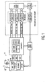
- Fig. 1 shows a block diagram of an LCOS projection television (TV) 10 having a viewer replaceable light source 11, e.g., a TV lamp, and a power button 12 that is selectively illuminated by a light source 13, such as an LED.
- the illumination of the power button is selectively controlled through a microprocessor 14 and an on-screen menu selection according to the present invention.
- FIG. 2 shows an example of such a menu 20. Should the viewer not want the power button on the front of the television to be continuously illuminated when the TV is on, the viewer can use the TV's on-screen menu 20 to turn off the LED.
- the "On When TV Is On” setting 21 in the menu 20 turns the LED 13 on only when the TV is powered on.
- the "On When TV Is On” setting 21 is preferably the default setting.
- the power button light setting is retained permanently even at power cycle or power removal.
- the power button menu 20 is set to "Off Always" to disable the power button LED 13, it does not disable the other indicator functions of the LED.
- the power button LED 13 can still be illuminated to indicate different information regarding the status of the TV, such as when, for example, the TV lamp is dead, an attempt to restart the TV lamp has failed, or the TV lamp is in its cool down mode and can therefore not be turned back on immediately.
- the system of the present invention may use any number of LEDs to both selectively illuminate the power button and serve as indication of the operating status of a video apparatus.
- at least one LED can be selectively programmed to blink for different periods of time, a different number of times and/or at a different speed to indicate different operating information regarding the status of the TV lamp.
- the duration, speed and number of times the at least one LED blinks are each selectively controllable. They can be selectively programmed by the manufacturer when the TV is fabricated. In an alternative embodiment these items can be selectively set or varied by the viewer.
- the system is typically software controlled by a programmable microprocessor, microcontroller or microcomputer, as represented by element 14 of Fig. 1.
- a system can operate as follows.
- the power button LED 13 will blink at an attention-getting rate, e.g., on for 200 msec, off for 200 msec, and then repeat.
- an attention-getting rate e.g., on for 200 msec, off for 200 msec, and then repeat.
- the assumption is that all other systems continue to operate normally (audio is heard, channels can be changed, power remains on, etc.) which will enable the viewer to diagnose the problem as an expired lamp module.
- This is advantageous because if the software turned off the television when the lamp module burned out, that would only further confuse the viewer since they might wrongly believe that a power surge, bad power supply or some other failure caused the picture to go out instead of the TV lamp.
- the blinking LED 13 in combination with the loss of picture will indicate to the viewer that something undesirable has occurred and that the viewer should read the viewer manual or call a service center for advice. Due to the possibility of false positives, e.g., the power button LED coming on when the lamp is actually working, the LED should blink only for one minute. However, if the TV is turned off, the blinking also stops. If the consumer tries to turn the TV on again when the TV is already on and the lamp has burned out, then the LED will blink for another minute. Under normal operation, the power button LED does not blink in response to IR commands.
- the power button LED also illuminates when a TV is in "cool down" mode. Cool down mode is at a time after the viewer has sent a power-off command to the TV and the TV cannot be turned back on instantaneously. This occurs because the high-intensity lamp of the TV must first de-energize before it can be relit otherwise the lamp life is shortened.
- the power button LED can be made to blink slowly, e.g., 500msec on/off three times, to let the viewer know that the command was received but the TV cannot act upon the command immediately.
- a system according to another aspect of the present invention can also include a "lamp restart failed" indicator. Before the TV determines that the lamp has failed, it will try three times to restart the lamp. Each time that it attempts to restart the lamp without success, a power button LED 13 can be made to blink, e.g., 5 times slowly, to indicate that lamp restart was unsuccessful. It will take three lamp restart attempts and up to a minute before the TV determines that the lamp may have failed and indicates this to the viewer by flashing the power button LED at a fast rate for one minute as described above.
- Table 1 below shows examples of different lamp status indicators that may be provided by the power button LED according to the present invention.
- the system of the present invention for selectively illuminating a power button can also be used in other devices to indicate information regarding the operating status of said device such as computers, stereos, medical equipment, manufacturing equipment, etc.
- the illumination source is not limited to LED, but may be an LCD display or other information display device.
Landscapes
- Engineering & Computer Science (AREA)
- Multimedia (AREA)
- Signal Processing (AREA)
- Transforming Electric Information Into Light Information (AREA)
- Circuit Arrangement For Electric Light Sources In General (AREA)
- Control Of Indicators Other Than Cathode Ray Tubes (AREA)
Abstract
Description
| Indicator Name | Blinks of Power Button LED | Speed of blinking |
| Lamp restart failed | Five blinks | "Fast" (200msec on/off) |
| Dead lamp | One minute of blinks | "Fast" (200msec on/off) |
| Cannot restart TV during cool down mode | Three blinks | "Slow" (500msec on/off) |
Claims (9)
- A system for indicating the status of a video apparatus, comprising:a power indicator illumination; anda user interface operative to allow a user to selectively illuminate the power indicator illumination when the video apparatus is powered on.
- The system of claim 1 wherein even when the power indicator illumination has been selected by the user to not be illuminated when the video apparatus is powered on, the power indicator illumination can still be illuminated to provide information to the user regarding operating status of the video apparatus.
- The system of claim 1, wherein the illumination is at least one light emitting diode (LED).
- The system of claim 1, wherein the user interface comprises an on-screen menu.
- The system of claim 4 further comprising a microprocessor for controlling the illumination in response to information entered by the user on the on-screen menu.
- The system of claim 2, wherein the illumination blinks at a plurality of different speeds, each speed indicating a different one of a plurality of operating status of the video apparatus.
- The system of Claim 2, wherein the operating status of the video apparatus comprising at least one of following conditions: non-operating projection lamp and cooling down of projection lamp.
- A method of controlling the power indicator illumination of an apparatus, comprising the steps of:illuminating the power indicator illumination of the apparatus when the apparatus is powered on; andproviding a user interface for allowing a user to selectively turn the power indicator illumination off, even when the apparatus is powered on.
- The method of claim 8 further comprising the step of allowing a microprocessor to illuminate the power indicator illumination of the apparatus, even if the user has selected to turn the power indicator illumination off.
Priority Applications (1)
| Application Number | Priority Date | Filing Date | Title |
|---|---|---|---|
| EP09176184A EP2154883B1 (en) | 2001-05-08 | 2002-04-29 | System for selectively extinguishing a light source that illuminates a television power button |
Applications Claiming Priority (4)
| Application Number | Priority Date | Filing Date | Title |
|---|---|---|---|
| US28941601P | 2001-05-08 | 2001-05-08 | |
| US289416P | 2001-05-08 | ||
| US10/020,421 US7209187B2 (en) | 2001-05-08 | 2001-12-13 | System for selectively extinguishing a light source that illuminates a television power button |
| US20421 | 2001-12-13 |
Related Child Applications (1)
| Application Number | Title | Priority Date | Filing Date |
|---|---|---|---|
| EP09176184A Division EP2154883B1 (en) | 2001-05-08 | 2002-04-29 | System for selectively extinguishing a light source that illuminates a television power button |
Publications (3)
| Publication Number | Publication Date |
|---|---|
| EP1257122A2 true EP1257122A2 (en) | 2002-11-13 |
| EP1257122A3 EP1257122A3 (en) | 2004-01-28 |
| EP1257122B1 EP1257122B1 (en) | 2009-12-30 |
Family
ID=26693415
Family Applications (2)
| Application Number | Title | Priority Date | Filing Date |
|---|---|---|---|
| EP02009661A Expired - Lifetime EP1257122B1 (en) | 2001-05-08 | 2002-04-29 | System for selectively extinguishing a light source that illuminates a television power button |
| EP09176184A Expired - Lifetime EP2154883B1 (en) | 2001-05-08 | 2002-04-29 | System for selectively extinguishing a light source that illuminates a television power button |
Family Applications After (1)
| Application Number | Title | Priority Date | Filing Date |
|---|---|---|---|
| EP09176184A Expired - Lifetime EP2154883B1 (en) | 2001-05-08 | 2002-04-29 | System for selectively extinguishing a light source that illuminates a television power button |
Country Status (7)
| Country | Link |
|---|---|
| US (1) | US7209187B2 (en) |
| EP (2) | EP1257122B1 (en) |
| JP (1) | JP4398136B2 (en) |
| KR (1) | KR100878542B1 (en) |
| CN (1) | CN1266928C (en) |
| DE (1) | DE60234892D1 (en) |
| MX (1) | MXPA02004677A (en) |
Cited By (1)
| Publication number | Priority date | Publication date | Assignee | Title |
|---|---|---|---|---|
| WO2004098181A1 (en) * | 2003-04-25 | 2004-11-11 | Thomson Licensing S.A. | Variable intensity illumination device with detection and control circuit for a front panel of a television apparatus |
Families Citing this family (13)
| Publication number | Priority date | Publication date | Assignee | Title |
|---|---|---|---|---|
| JP3693112B2 (en) * | 2003-01-23 | 2005-09-07 | 船井電機株式会社 | Digital broadcast receiver |
| US8384651B2 (en) * | 2003-04-24 | 2013-02-26 | Thomson Licensing | Lamp protection system and method |
| KR100686028B1 (en) * | 2005-02-21 | 2007-02-22 | 엘지전자 주식회사 | Light control device and method of the projector |
| US20060189347A1 (en) * | 2005-02-22 | 2006-08-24 | Bollman William H | Wireless phone device flashlight |
| KR100688666B1 (en) * | 2005-11-02 | 2007-03-02 | 엘지전자 주식회사 | Wireless transmitter, wireless television, and wireless television system having auto-off transmission / reception light emitting unit and control method thereof |
| US7654858B2 (en) * | 2007-02-12 | 2010-02-02 | Microsoft Corporation | Indicator light for connector |
| US20090122045A1 (en) * | 2007-11-09 | 2009-05-14 | Kabushiki Kaisha Toshiba | Power Source Display Apparatus, Power Source Display Method, and Electronic Apparatus |
| US20100289942A1 (en) * | 2009-05-18 | 2010-11-18 | Sony Corporation And Sony Electronics | Feedback system for optimizing exposure |
| US8770815B2 (en) * | 2009-05-18 | 2014-07-08 | Sony Corporation | Active bezel edge lighting with diffuser layer |
| WO2012164769A1 (en) * | 2011-06-03 | 2012-12-06 | 株式会社ソニー・コンピュータエンタテインメント | Video display device |
| KR20150090181A (en) * | 2012-12-05 | 2015-08-05 | 캐논 가부시끼가이샤 | Image forming apparatus, and method for controlling image forming apparatus |
| JP2023177610A (en) | 2022-06-02 | 2023-12-14 | キヤノン株式会社 | Image processing device, image processing method and computer program |
| JP7809626B2 (en) | 2022-11-07 | 2026-02-02 | キヤノン株式会社 | Information processing device, information processing method, and computer program |
Family Cites Families (21)
| Publication number | Priority date | Publication date | Assignee | Title |
|---|---|---|---|---|
| US4989081A (en) * | 1988-11-14 | 1991-01-29 | Sony Corporation | Home-bus-information system |
| US5136397A (en) | 1989-10-31 | 1992-08-04 | Seiko Epson Corporation | Liquid crystal video projector having lamp and cooling control and remote optics and picture attribute controls |
| US5612749A (en) * | 1994-06-27 | 1997-03-18 | Bacher; Emil G. | Apparatus and method for receiving messages from a central transmitter with a television receiver |
| US5548832A (en) * | 1994-07-28 | 1996-08-20 | Uniden America Corporation | Automatic display illumination in a receiver |
| JPH0965224A (en) * | 1995-08-24 | 1997-03-07 | Hitachi Ltd | TV receiver |
| US5929943A (en) * | 1995-12-28 | 1999-07-27 | Thomson Consumer Electronics, Inc. | Automatic plug-in indicator dimmer |
| KR100245202B1 (en) * | 1997-03-07 | 2000-02-15 | 윤종용 | An apparatus for power control and its method in a computer system |
| JPH10274950A (en) * | 1997-03-31 | 1998-10-13 | Sony Corp | Electronics |
| JPH11220678A (en) | 1998-01-30 | 1999-08-10 | Sanyo Electric Co Ltd | Television receiver |
| JPH11289502A (en) | 1998-04-03 | 1999-10-19 | Sanyo Electric Co Ltd | Television receiver |
| US6593972B1 (en) * | 1998-05-12 | 2003-07-15 | Clark E. Johnson, Jr. | Interactive display system |
| JP3282721B2 (en) * | 1999-02-02 | 2002-05-20 | 日本電気株式会社 | Portable wireless communication device |
| JP2001086233A (en) * | 1999-07-13 | 2001-03-30 | Denso Corp | Mobile device with lighting function |
| US6456421B1 (en) * | 1999-09-01 | 2002-09-24 | Polaroid Corporation | System for printing with programmable spatial light modulator and method |
| JP3496589B2 (en) * | 1999-09-21 | 2004-02-16 | 日本電気株式会社 | Information processing equipment |
| JP4024444B2 (en) * | 1999-12-27 | 2007-12-19 | 株式会社東芝 | Wireless telephone equipment |
| US6224216B1 (en) * | 2000-02-18 | 2001-05-01 | Infocus Corporation | System and method employing LED light sources for a projection display |
| GB0015542D0 (en) | 2000-06-27 | 2000-08-16 | Pace Micro Tech Plc | Front panel display |
| US6556971B1 (en) * | 2000-09-01 | 2003-04-29 | Snap-On Technologies, Inc. | Computer-implemented speech recognition system training |
| US6704061B2 (en) * | 2001-01-04 | 2004-03-09 | Rhomson Licensing S.A. | Temporary simulated off state in a restart of a video display |
| US7117019B2 (en) * | 2001-03-30 | 2006-10-03 | Motorola, Inc. | Display and keypad backlight management for portable electronic devices |
-
2001
- 2001-12-13 US US10/020,421 patent/US7209187B2/en not_active Expired - Lifetime
-
2002
- 2002-04-29 EP EP02009661A patent/EP1257122B1/en not_active Expired - Lifetime
- 2002-04-29 EP EP09176184A patent/EP2154883B1/en not_active Expired - Lifetime
- 2002-04-29 DE DE60234892T patent/DE60234892D1/en not_active Expired - Lifetime
- 2002-05-01 JP JP2002130135A patent/JP4398136B2/en not_active Expired - Lifetime
- 2002-05-06 KR KR1020020024757A patent/KR100878542B1/en not_active Expired - Lifetime
- 2002-05-08 CN CNB021190526A patent/CN1266928C/en not_active Expired - Lifetime
- 2002-05-08 MX MXPA02004677A patent/MXPA02004677A/en active IP Right Grant
Cited By (2)
| Publication number | Priority date | Publication date | Assignee | Title |
|---|---|---|---|---|
| WO2004098181A1 (en) * | 2003-04-25 | 2004-11-11 | Thomson Licensing S.A. | Variable intensity illumination device with detection and control circuit for a front panel of a television apparatus |
| US7532251B2 (en) | 2003-04-25 | 2009-05-12 | Thomson Licensing | Variable intensity illumination device with detection and control circuit for a front panel of a television apparatus |
Also Published As
| Publication number | Publication date |
|---|---|
| DE60234892D1 (en) | 2010-02-11 |
| US20020186325A1 (en) | 2002-12-12 |
| MXPA02004677A (en) | 2004-07-16 |
| KR100878542B1 (en) | 2009-01-14 |
| CN1266928C (en) | 2006-07-26 |
| KR20020085813A (en) | 2002-11-16 |
| JP4398136B2 (en) | 2010-01-13 |
| EP1257122B1 (en) | 2009-12-30 |
| JP2002354363A (en) | 2002-12-06 |
| EP2154883B1 (en) | 2011-06-22 |
| EP2154883A1 (en) | 2010-02-17 |
| EP1257122A3 (en) | 2004-01-28 |
| CN1386008A (en) | 2002-12-18 |
| US7209187B2 (en) | 2007-04-24 |
Similar Documents
| Publication | Publication Date | Title |
|---|---|---|
| US7209187B2 (en) | System for selectively extinguishing a light source that illuminates a television power button | |
| US5136397A (en) | Liquid crystal video projector having lamp and cooling control and remote optics and picture attribute controls | |
| USRE36060E (en) | Liquid crystal video projector having lamp and cooling control and remote optics and picture attribute controls | |
| US6459938B1 (en) | Remote supervisory control system | |
| US7824039B2 (en) | Projector | |
| US6874892B1 (en) | Color setting monitoring system for a digital projector | |
| US20100107019A1 (en) | Remote control unit of air conditioning apparatus | |
| CN102043311A (en) | Image display apparatus with external-equipment-link unit | |
| US7461941B2 (en) | Uninterrupted power supply for projection lamp protection | |
| US20100053475A1 (en) | Illuminated status indicator for an image display device | |
| JP2008278253A (en) | Camera status display device | |
| JP2004309691A (en) | Projection device | |
| JP4747606B2 (en) | Lighting device and lighting system | |
| EP1616437A2 (en) | Lamp protection system and method | |
| JP2003280088A (en) | Projector device | |
| JPH10318591A (en) | Air conditioner | |
| JP2005128712A (en) | Electronics | |
| JP2010008452A (en) | Image display device | |
| JP4744274B2 (en) | Video camera equipment | |
| CA2193185A1 (en) | Light-incorporated video camera | |
| TWI224303B (en) | Temporary simulated off state in a restart of a video display | |
| KR100932747B1 (en) | LCD video display device displaying OSD screen with lamp OFF | |
| JP2004294852A (en) | Optical device | |
| JPH0851650A (en) | Self-diagnosis display device | |
| JPH04163586A (en) | Projection type image display device |
Legal Events
| Date | Code | Title | Description |
|---|---|---|---|
| PUAI | Public reference made under article 153(3) epc to a published international application that has entered the european phase |
Free format text: ORIGINAL CODE: 0009012 |
|
| AK | Designated contracting states |
Kind code of ref document: A2 Designated state(s): AT BE CH CY DE DK ES FI FR GB GR IE IT LI LU MC NL PT SE TR |
|
| AX | Request for extension of the european patent |
Free format text: AL;LT;LV;MK;RO;SI |
|
| RIN1 | Information on inventor provided before grant (corrected) |
Inventor name: JOHNSON, GENE HARLOW Inventor name: GOSPEL, THOMAS EDWARD Inventor name: MEARS, MARK GILMORE Inventor name: MUNSON, WESLEY GUY |
|
| PUAL | Search report despatched |
Free format text: ORIGINAL CODE: 0009013 |
|
| AK | Designated contracting states |
Kind code of ref document: A3 Designated state(s): AT BE CH CY DE DK ES FI FR GB GR IE IT LI LU MC NL PT SE TR |
|
| AX | Request for extension of the european patent |
Extension state: AL LT LV MK RO SI |
|
| 17P | Request for examination filed |
Effective date: 20040701 |
|
| AKX | Designation fees paid |
Designated state(s): DE GB |
|
| 17Q | First examination report despatched |
Effective date: 20050118 |
|
| RAP1 | Party data changed (applicant data changed or rights of an application transferred) |
Owner name: THOMSON LICENSING |
|
| 17Q | First examination report despatched |
Effective date: 20050118 |
|
| GRAP | Despatch of communication of intention to grant a patent |
Free format text: ORIGINAL CODE: EPIDOSNIGR1 |
|
| GRAS | Grant fee paid |
Free format text: ORIGINAL CODE: EPIDOSNIGR3 |
|
| GRAA | (expected) grant |
Free format text: ORIGINAL CODE: 0009210 |
|
| AK | Designated contracting states |
Kind code of ref document: B1 Designated state(s): DE GB |
|
| REG | Reference to a national code |
Ref country code: GB Ref legal event code: FG4D |
|
| REF | Corresponds to: |
Ref document number: 60234892 Country of ref document: DE Date of ref document: 20100211 Kind code of ref document: P |
|
| RAP2 | Party data changed (patent owner data changed or rights of a patent transferred) |
Owner name: THOMSON LICENSING |
|
| REG | Reference to a national code |
Ref country code: GB Ref legal event code: 746 Effective date: 20100202 |
|
| PLBE | No opposition filed within time limit |
Free format text: ORIGINAL CODE: 0009261 |
|
| STAA | Information on the status of an ep patent application or granted ep patent |
Free format text: STATUS: NO OPPOSITION FILED WITHIN TIME LIMIT |
|
| 26N | No opposition filed |
Effective date: 20101001 |
|
| REG | Reference to a national code |
Ref country code: DE Ref legal event code: R081 Ref document number: 60234892 Country of ref document: DE Owner name: INTERDIGITAL MADISON PATENT HOLDINGS, FR Free format text: FORMER OWNER: THOMSON LICENSING, ISSY-LES-MOULINEAUX, FR Ref country code: DE Ref legal event code: R082 Ref document number: 60234892 Country of ref document: DE Representative=s name: DEHNS, DE Ref country code: DE Ref legal event code: R082 Ref document number: 60234892 Country of ref document: DE Representative=s name: ROSSMANITH, MANFRED, DIPL.-PHYS. DR.RER.NAT., DE Ref country code: DE Ref legal event code: R081 Ref document number: 60234892 Country of ref document: DE Owner name: THOMSON LICENSING DTV SAS, FR Free format text: FORMER OWNER: THOMSON LICENSING, ISSY-LES-MOULINEAUX, FR Ref country code: DE Ref legal event code: R082 Ref document number: 60234892 Country of ref document: DE Representative=s name: HOFSTETTER, SCHURACK & PARTNER PATENT- UND REC, DE |
|
| REG | Reference to a national code |
Ref country code: DE Ref legal event code: R082 Ref document number: 60234892 Country of ref document: DE Representative=s name: DEHNS, DE Ref country code: DE Ref legal event code: R082 Ref document number: 60234892 Country of ref document: DE Representative=s name: DEHNS PATENT AND TRADEMARK ATTORNEYS, DE Ref country code: DE Ref legal event code: R082 Ref document number: 60234892 Country of ref document: DE Representative=s name: HOFSTETTER, SCHURACK & PARTNER PATENT- UND REC, DE |
|
| REG | Reference to a national code |
Ref country code: GB Ref legal event code: 732E Free format text: REGISTERED BETWEEN 20170717 AND 20170719 |
|
| REG | Reference to a national code |
Ref country code: GB Ref legal event code: 732E Free format text: REGISTERED BETWEEN 20180927 AND 20181005 |
|
| REG | Reference to a national code |
Ref country code: DE Ref legal event code: R082 Ref document number: 60234892 Country of ref document: DE Representative=s name: DEHNS, DE Ref country code: DE Ref legal event code: R081 Ref document number: 60234892 Country of ref document: DE Owner name: INTERDIGITAL MADISON PATENT HOLDINGS, FR Free format text: FORMER OWNER: THOMSON LICENSING DTV SAS, LSSY-LES-MOULINEAUX, FR Ref country code: DE Ref legal event code: R082 Ref document number: 60234892 Country of ref document: DE Representative=s name: DEHNS PATENT AND TRADEMARK ATTORNEYS, DE |
|
| PGFP | Annual fee paid to national office [announced via postgrant information from national office to epo] |
Ref country code: DE Payment date: 20210428 Year of fee payment: 20 |
|
| PGFP | Annual fee paid to national office [announced via postgrant information from national office to epo] |
Ref country code: GB Payment date: 20210426 Year of fee payment: 20 |
|
| REG | Reference to a national code |
Ref country code: DE Ref legal event code: R071 Ref document number: 60234892 Country of ref document: DE |
|
| REG | Reference to a national code |
Ref country code: GB Ref legal event code: PE20 Expiry date: 20220428 |
|
| PG25 | Lapsed in a contracting state [announced via postgrant information from national office to epo] |
Ref country code: GB Free format text: LAPSE BECAUSE OF EXPIRATION OF PROTECTION Effective date: 20220428 |