EP1257040A2 - Fractional-slot winding motor - Google Patents
Fractional-slot winding motor Download PDFInfo
- Publication number
- EP1257040A2 EP1257040A2 EP02076492A EP02076492A EP1257040A2 EP 1257040 A2 EP1257040 A2 EP 1257040A2 EP 02076492 A EP02076492 A EP 02076492A EP 02076492 A EP02076492 A EP 02076492A EP 1257040 A2 EP1257040 A2 EP 1257040A2
- Authority
- EP
- European Patent Office
- Prior art keywords
- slot
- slots
- beginning
- stator
- motor
- Prior art date
- Legal status (The legal status is an assumption and is not a legal conclusion. Google has not performed a legal analysis and makes no representation as to the accuracy of the status listed.)
- Granted
Links
Images


Classifications
-
- H—ELECTRICITY
- H02—GENERATION; CONVERSION OR DISTRIBUTION OF ELECTRIC POWER
- H02K—DYNAMO-ELECTRIC MACHINES
- H02K3/00—Details of windings
- H02K3/04—Windings characterised by the conductor shape, form or construction, e.g. with bar conductors
- H02K3/28—Layout of windings or of connections between windings
-
- H—ELECTRICITY
- H02—GENERATION; CONVERSION OR DISTRIBUTION OF ELECTRIC POWER
- H02K—DYNAMO-ELECTRIC MACHINES
- H02K29/00—Motors or generators having non-mechanical commutating devices, e.g. discharge tubes or semiconductor devices
- H02K29/03—Motors or generators having non-mechanical commutating devices, e.g. discharge tubes or semiconductor devices with a magnetic circuit specially adapted for avoiding torque ripples or self-starting problems
-
- Y—GENERAL TAGGING OF NEW TECHNOLOGICAL DEVELOPMENTS; GENERAL TAGGING OF CROSS-SECTIONAL TECHNOLOGIES SPANNING OVER SEVERAL SECTIONS OF THE IPC; TECHNICAL SUBJECTS COVERED BY FORMER USPC CROSS-REFERENCE ART COLLECTIONS [XRACs] AND DIGESTS
- Y10—TECHNICAL SUBJECTS COVERED BY FORMER USPC
- Y10T—TECHNICAL SUBJECTS COVERED BY FORMER US CLASSIFICATION
- Y10T29/00—Metal working
- Y10T29/49—Method of mechanical manufacture
- Y10T29/49002—Electrical device making
- Y10T29/49009—Dynamoelectric machine
Definitions
- Polyphase permanent magnet, brushless motors driven by a sinusoidal current offer the capability of providing low torque ripple, noise and vibration in comparison with those driven by a square wave current.
- a motor controller can produce polyphase sinusoidal currents with the same frequency as that of the sinusoidal back EMFs, the torque output of the motor will be a constant, and zero torque ripple can be achieved.
- Cogging torque is a result of the magnetic interaction between the permanent magnets of the rotor and the slotted structure of the armature. As the leading edge of a magnet approaches an individual stator tooth, a positive torque is produced by the magnetic attraction force exerted therebetween. However, as the magnet leading edge passes and the trailing edge approaches, a negative torque is produced.
- the instantaneous value of the cogging torque varies with rotor position and alternates at a frequency that is proportional to the motor speed and the number of slots. The amplitude of the cogging torque is affected by certain design parameters such as slot opening/slot pitch ratio, magnet strength and air gap length.
- One approach to reduce cogging torque is to skew either the stator teeth or the rotor magnet longitudinally, which provides for a gradual transition as the magnet moves under a stator tooth.
- An alternative approach is to employ a slotless armature, which allows for precise winding patterns in order to achieve a pure sinusoidal back EMF.
- the absence of slots in the armature eliminates the cogging torque resulting therefrom.
- the manufacturing process for slotless motors is not well defined and thus the manufacturing costs thereof may be prohibitive.
- the motor includes a permanent magnet rotor having a plurality of magnetic poles thereupon and a stator.
- the stator further includes a plurality of stacked laminations defining a plurality of slots therein, and a plurality of fractional-pitch phase windings disposed within the plurality of slots.
- the motor has a non-integer slots-per-pole ratio, and a magnitude of 5 th and 7 th harmonic components of a fundamental frequency component of the motor are less than 0.3% and 0.1% of a magnitude of the fundamental frequency component, respectively.
- the stator is wound with three separate phase windings. Each of the three separate phase windings further includes three parallel branches, with each parallel branch having a plurality of serially connected coil segments.
- each of the phase windings are wound in the stator according to the following pattern:
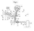
- Electric power steering system 12 may include a conventional rack and pinion steering mechanism 14 having a toothed rack 15 and a pinion gear (not shown) under a gear housing 16.
- an upper steering shaft 20 turns a lower shaft 22 through a universal joint 24.
- Lower steering shaft 22 turns the pinion gear.
- the rotation of the pinion gear moves the pinion rack 15, which then moves tie rods 28 (only one shown).
- tie rods 28 move steering knuckles 30 (only one shown) to turn wheels 32.
- Controller 34 receives electric power from a vehicle electric power source 38 through a line 40.
- the controller 34 also receives a signal representative of the vehicle velocity on line 41, as well as steering pinion gear angle from a rotational position sensor 42 on line 44.
- a torque sensor 46 senses the torque applied to steering wheel 18 by the vehicle operator and provides an operator torque signal to controller 34 on line 48.
- rotor position signals for each phase are generated within motor 36 and provided over bus 50 to controller 34.
- the controller 34 derives desired motor phase currents.
- the motor phase currents are provided to motor 36 through a bus 52 to motor 36, which thereby provides torque assist to steering shaft 20 through worm 54 and worm gear 56.
- brushless motor 36 in accordance with an embodiment of the invention has a six-pole, permanent magnet rotor 60, which is mounted on a shaft 62 and has six magnetic poles 64.
- a stator 66 features stacked laminations 68 defining twenty-seven slots 70.
- Each of the twenty-seven slots 70 are individually numbered in Figure 2, beginning at slot 1 and proceeding clockwise to slot 27.
- each slot 70 houses two phase coils. As is described in further detail later, some slots will contain coils from the same phase, while other slots will have coils from two different phases. Because the number of slots/number of poles ratio is a non-integer, motor 36 is a fractional-slot winding motor.
- brushless motor 36 being a fractional-slot winding motor, may have a different number of poles (e.g., 4) or a different number of slots (e.g., 18) so long as the slots per pole ratio thereby is a non-integer.
- Either the rotor poles 64 or the stator slots 70 may be skewed from the motor axis in a normal manner, such that the poles 64 and slots 70 are skewed by one slot pitch axially across the stator. It should be understood that, according to conventional industry practice, the skew may be slightly more or less (up to 5%) than one slot pitch to compensate for certain fringing effects. Any such variations in skew are intended to be included in the commonly understood meaning of the phrase "one slot pitch".
- each of the three phases has three parallel branches of windings.
- Each parallel winding branch in turn, has three serially connected coil segments 72.
- each winding phase “A”, “B” and “C” has three branches of windings designated as A 1 , A 2 and A 3 ; B 1 , B 2 and B 3 ; C 1 , C 2 and C 3 .
- the designations shown on each coil segment 72 represent the starting slot and the finishing slot for each segment. Specifically, the number in the designation represents the slot number and the letter (S or F) indicates whether the coil segment starts or finishes at that slot number.
- winding branch A 1 of phase winding "A” has a first coil segment starting at slot 1 (1S) and ending at slot 24 (24F).
- a second coil segment is thereafter connected in series with the first coil segment, and starting again at slot 1 (1S) and ending at slot 5 (5F). Finally, a third coil segment is connected in series with the second coil segment. Third coil segment begins at slot 2 (2S) and ends at slot 6 (6F).
- winding branch A 1 begins by traveling inward through slot 1. Accordingly, the designation A 1 x is shown in the outer layer of slot 1. Following the above described pattern, winding A 1 then travels back outward in slot 24, which is four slots counterclockwise from slot 1. Thus, the designation A 1 • appears in the outer layer of slot 24. Continuing with the above winding pattern, the remaining segments of winding A 1 are represented by: A 1 x in slot 1 (again), A 1 • in slot 5, A 1 x in slot 2, and finally A 1 • in slot 6.
- winding branches for a given phase are spaced apart from one another by 9 slots, or 120 mechanical degrees, while the winding branches of corresponding phases (e.g., A 1 , B 1 , C 1 ) are spaced apart by 3 slots, or 30 mechanical degrees.
- the magnitude of the 5 th & 7 th harmonic components are reduced to less than 0.3% and 0.1% of the fundamental frequency component, respectively.
Landscapes
- Engineering & Computer Science (AREA)
- Power Engineering (AREA)
- Windings For Motors And Generators (AREA)
- Permanent Magnet Type Synchronous Machine (AREA)
- Iron Core Of Rotating Electric Machines (AREA)
Abstract
Description
While the invention has been described with reference to a preferred embodiment, it will be understood by those skilled in the art that various changes may be made and equivalents may be substituted for elements thereof without departing from the scope of the invention. In addition, many modifications may be made to adapt a particular situation or material to the teachings of the invention without departing from the essential scope thereof. Therefore, it is intended that the invention not be limited to the particular embodiment disclosed as the best mode contemplated for carrying out this invention, but that the invention will include all embodiments falling within the scope of the appended claims.
Claims (13)
- A brushless electric motor (36), comprising:wherein the motor (36) has a non-integer slots-per-pole ratio, anda permanent magnet rotor (60), said rotor (60) having a plurality of magnetic poles (64) thereupon; anda stator (66), said stator (66) further comprising a plurality of stacked laminations (68) defining a plurality of slots (70) therein; anda plurality of fractional-pitch phase windings disposed within said plurality of slots (70);a magnitude of 5th and 7th harmonic components of a fundamental frequency component of the motor are less than 0.3% and 0.1% of a magnitude of said fundamental frequency component, respectively.
- The brushless motor (36) of claim 1, wherein said stator (66) is wound with three separate phase windings.
- The brushless motor (36) of claim 2, wherein each of said three separate phase windings further comprises:a plurality of parallel branches, with each parallel branch having a plurality of serially connected coil segments (72).
- The brushless motor (36) of claim 3, wherein each of said three separate phase windings further comprises:three parallel branches, with each parallel branch having three serially connected coil segments (72).
- The brushless motor (36) of claim 2, wherein each of said phase windings are wound in said stator (66) according to the following pattern:traveling inward, through a beginning slot, then;traveling outward, through a second slot which is four slots counterclockwise from said beginning slot, then;traveling inward, through said beginning slot, then;traveling outward, through a third slot which is four slots clockwise from said beginning slot, then;traveling inward, through a fourth slot which is one slot clockwise from said beginning slot; thentraveling outward, through a fifth slot which is five slots clockwise from said beginning slot.
- The brushless motor (36) of claim 5, wherein said stator (66) further comprises 27 slots (70) and said rotor (60) further comprises 6 poles (64).
- A power assist actuator for an electric power steering system (12), the actuator comprising:wherein said motor (36) has a non-integer slots-per-pole ratio, anda brushless motor (36) coupled to a steering shaft (20), (22) and providing an assist torque thereon, said motor (36) further comprising:a permanent magnet rotor (60), said rotor (60) having a plurality of magnetic poles (64) thereupon; anda stator (66), said stator (66) further comprising a plurality of stacked laminations (68) defining a plurality of slots (70) therein; anda plurality of fractional-pitch phase windings disposed within said plurality of slots (70);a magnitude of 5th and 7th harmonic components of a fundamental frequency component of said motor (36) are less than 0.3% and 0.1% of a magnitude of said fundamental frequency component, respectively.
- The power assist actuator of claim 7, wherein said stator (66) is wound with three separate phase windings.
- The power assist actuator of claim 8, wherein each of said three separate phase windings further comprises:a plurality of parallel branches, with each parallel branch having a plurality of serially connected coil segments (72).
- The power assist actuator of claim 9, wherein each of said three separate phase windings further comprises:three parallel branches, with each parallel branch having three serially connected coil segments (72).
- The power assist actuator of claim 8, wherein each of said phase windings are wound in said stator (66) according to the following pattern:traveling inward, through a beginning slot, then;traveling outward, through a second slot which is four slots counterclockwise from said beginning slot, then;traveling inward, through said beginning slot, then;traveling outward, through a third slot which is four slots clockwise from said beginning slot, then;traveling inward, through a fourth slot which is one slot clockwise from said beginning slot; thentraveling outward, through a fifth slot which is five slots clockwise from said beginning slot.
- The power assist actuator of claim 11, wherein said stator (66) further comprises 27 slots (70) and said rotor (60) further comprises 6 poles (64).
- A method for winding a stator (66) of a brushless motor (36) having a permanent magnet rotor (60) and a plurality of slots (70) formed within the stator (66), the method comprising:starting at a beginning slot, running a winding branch through said beginning slot in an inward direction; thenrunning said branch through a second slot in an outward direction, said second slot being four slots counterclockwise from said beginning slot; thenrunning said branch through said beginning slot in said inward direction; thenrunning said branch through a third slot in said outward direction, said third slot being four slots clockwise from said beginning slot; thenrunning said branch through a fourth slot in said inward direction, said fourth slot being one slot clockwise from said beginning slot; andrunning said branch through a fifth slot in said outward direction, said fifth slot being five slots clockwise from said beginning slot.
Applications Claiming Priority (2)
| Application Number | Priority Date | Filing Date | Title |
|---|---|---|---|
| US09/850,758 US6759780B2 (en) | 2001-05-08 | 2001-05-08 | Fractional-slot winding motor |
| US850758 | 2001-05-08 |
Publications (4)
| Publication Number | Publication Date |
|---|---|
| EP1257040A2 true EP1257040A2 (en) | 2002-11-13 |
| EP1257040A3 EP1257040A3 (en) | 2004-01-02 |
| EP1257040B1 EP1257040B1 (en) | 2010-12-01 |
| EP1257040B2 EP1257040B2 (en) | 2014-08-13 |
Family
ID=25309031
Family Applications (1)
| Application Number | Title | Priority Date | Filing Date |
|---|---|---|---|
| EP02076492.4A Expired - Lifetime EP1257040B2 (en) | 2001-05-08 | 2002-04-15 | Fractional-slot winding motor |
Country Status (4)
| Country | Link |
|---|---|
| US (1) | US6759780B2 (en) |
| EP (1) | EP1257040B2 (en) |
| JP (1) | JP2002345191A (en) |
| DE (1) | DE60238460D1 (en) |
Cited By (7)
| Publication number | Priority date | Publication date | Assignee | Title |
|---|---|---|---|---|
| FR2869478A1 (en) * | 2004-04-23 | 2005-10-28 | Renault Sas | SYNCHRONOUS MOTOR WITH LOW TORQUE INJULATIONS, PROCESS FOR REALIZING THE WINDING OF THIS MOTOR, AND POWER ASSISTED STEERING OF A MOTOR VEHICLE COMPRISING SUCH AN ENGINE |
| WO2006029671A1 (en) * | 2004-09-18 | 2006-03-23 | Zf Friedrichshafen Ag | Regulating device for a regulating or control element |
| WO2010040785A3 (en) * | 2008-10-09 | 2010-12-02 | Feaam Gmbh | Electric motor |
| US7928624B2 (en) | 2006-12-21 | 2011-04-19 | Kone Corporation | Electric motor |
| DE102010003217A1 (en) * | 2010-03-24 | 2011-09-29 | Brose Fahrzeugteile GmbH & Co. Kommanditgesellschaft, Würzburg | Electric machine and steering device |
| CN108462274A (en) * | 2017-02-17 | 2018-08-28 | 福特全球技术公司 | Motor with the stator winding for reducing torque ripple |
| CN116076004A (en) * | 2020-09-02 | 2023-05-05 | 三菱电机株式会社 | Stator, electric motor, compressor, air conditioner, and stator manufacturing method |
Families Citing this family (43)
| Publication number | Priority date | Publication date | Assignee | Title |
|---|---|---|---|---|
| SE523478C2 (en) * | 2003-04-14 | 2004-04-20 | Swedish Seabased Energy Ab | Wave energy machine, includes linear electric generator with electromagnetic damping devices |
| TWM246600U (en) * | 2003-12-31 | 2004-10-11 | Taigene Metal Industry Co Ltd | Magnetic sensor |
| US20050174006A1 (en) * | 2004-02-06 | 2005-08-11 | Valeo Electrical Systems, Inc. | Winding topologies for stators in brushless motors |
| JP4546112B2 (en) * | 2004-03-02 | 2010-09-15 | 日立オートモティブシステムズ株式会社 | Rotating electric machine |
| US6949901B1 (en) | 2004-08-30 | 2005-09-27 | Delphi Technologies, Inc. | System and method for controlling a steering position of rear vehicle wheels |
| JP4617992B2 (en) * | 2005-04-28 | 2011-01-26 | トヨタ自動車株式会社 | Winding structure of rotating electrical machine |
| US7348705B2 (en) * | 2005-07-21 | 2008-03-25 | Remy Technologies, L.L.C. | Multi-phase fractional slot windings for electric machines having segmented bar-shaped windings |
| CN100405704C (en) * | 2005-08-31 | 2008-07-23 | 北京中科三环高技术股份有限公司 | Fractional slot winding of low-speed large-torque permanent magnet brushless motor |
| JP4745857B2 (en) * | 2006-02-20 | 2011-08-10 | 三菱電機株式会社 | Electric machine |
| US8944783B2 (en) * | 2006-06-27 | 2015-02-03 | Schlumberger Technology Corporation | Electric progressive cavity pump |
| US7549504B2 (en) * | 2006-07-28 | 2009-06-23 | Delphi Technologies, Inc. | Quadrant dependent active damping for electric power steering |
| US7543679B2 (en) | 2006-07-28 | 2009-06-09 | Delphi Technologies, Inc. | Compensation of periodic sensor errors in electric power steering systems |
| US7725227B2 (en) | 2006-12-15 | 2010-05-25 | Gm Global Technology Operations, Inc. | Method, system, and apparatus for providing enhanced steering pull compensation |
| JP5150930B2 (en) * | 2007-11-07 | 2013-02-27 | 本田技研工業株式会社 | Outer rotor type multi-pole generator |
| US7876016B2 (en) * | 2007-11-15 | 2011-01-25 | Sundyne Corporation | Stator winding method and apparatus |
| JP2010130821A (en) * | 2008-11-28 | 2010-06-10 | Hitachi Ltd | Winding structure of rotary electric machine, and drive system of the rotary electric machine |
| US7913375B2 (en) * | 2009-01-19 | 2011-03-29 | Sergey Pulnikov | Method for making electrical windings for electrical machines and winding obtained by said method |
| ITBO20090075A1 (en) * | 2009-02-13 | 2010-08-14 | Magneti Marelli Spa | ELECTRIC MACHINE WITH SINGLE STATOR AND TWO ROTORS BETWEEN THEM INDEPENDENT AND ROAD VEHICLE PROVIDED WITH THIS ELECTRIC MACHINE |
| EP2284978A1 (en) * | 2009-08-03 | 2011-02-16 | Converteam Technology Ltd | Armature windings |
| CN102025248B (en) | 2009-09-18 | 2014-03-12 | 德昌电机(深圳)有限公司 | Motor used for power system of electric vehicle |
| US8689879B2 (en) | 2010-04-08 | 2014-04-08 | Schlumberger Technology Corporation | Fluid displacement methods and apparatus for hydrocarbons in subsea production tubing |
| US20120043846A1 (en) * | 2010-08-23 | 2012-02-23 | Emerson Electric Co | Motor with impedance balanced winding |
| KR101403831B1 (en) * | 2010-09-20 | 2014-06-03 | 한라비스테온공조 주식회사 | Electric motor-driven compressor for vehicle |
| JP5354302B2 (en) * | 2010-12-13 | 2013-11-27 | 株式会社デンソー | Rotating electric machine stator |
| CN102064649B (en) * | 2010-12-27 | 2013-03-13 | 北京华怡净化科技研究所有限公司 | Three-phase rare-earth permanent magnet fractional slot concentrated winding synchronous generator |
| JP5000773B2 (en) * | 2011-03-31 | 2012-08-15 | 三菱電機株式会社 | Electric machine |
| JP2013071550A (en) * | 2011-09-27 | 2013-04-22 | Jtekt Corp | Control unit for vehicle steering system |
| GB2508416A (en) * | 2012-11-30 | 2014-06-04 | Univ Sheffield | Reducing dominant undesirable harmonics in an electric machine |
| US20140167547A1 (en) * | 2012-12-14 | 2014-06-19 | GM Global Technology Operations LLC | Electric machine with fractional slot windings |
| JP2015130724A (en) * | 2014-01-06 | 2015-07-16 | 日本精工株式会社 | Motor core and motor |
| US20150270747A1 (en) * | 2014-03-24 | 2015-09-24 | The Texas A&M University System | System and method for controlling multiphase electric motors |
| JP6117740B2 (en) * | 2014-06-18 | 2017-04-19 | ファナック株式会社 | 3-phase AC motor with torque ripple reduction structure |
| TWI574489B (en) | 2014-08-01 | 2017-03-11 | 飛爾康動力公司 | Propulsion system, motor/generator/transmission device and method of operation thereof |
| US11296638B2 (en) * | 2014-08-01 | 2022-04-05 | Falcon Power, LLC | Variable torque motor/generator/transmission |
| JP6235504B2 (en) | 2015-02-17 | 2017-11-22 | ファナック株式会社 | Radial gap type motor with distributed winding and winding arrangement method thereof |
| JP6550846B2 (en) * | 2015-03-27 | 2019-07-31 | アイシン精機株式会社 | Rotating electric machine |
| US9979248B2 (en) * | 2015-06-29 | 2018-05-22 | General Electric Company | Short circuit fault tolerant permanent magnet machine |
| US10256682B2 (en) * | 2016-09-28 | 2019-04-09 | Emerson Electric Co. | Stator assemblies for three phase dynamoelectric machines and related winding methods |
| US10644558B2 (en) | 2016-12-14 | 2020-05-05 | Transportation Ip Holdings, Llc | System, method, and apparatus for stator and alternator for electric machine |
| CN109861414A (en) * | 2017-11-30 | 2019-06-07 | 日本电产株式会社 | Rotor, motor and the electrical equipment comprising the motor |
| US10734876B2 (en) | 2018-03-19 | 2020-08-04 | Denso International America, Inc. | Brushless motor for HVAC system |
| US11532961B2 (en) | 2018-09-21 | 2022-12-20 | Steering Solutions Ip Holding Corporation | Pole lobed rotor core |
| WO2021061795A1 (en) * | 2019-09-23 | 2021-04-01 | Canoo Inc. | Fractional slot electric motors with coil elements having rectangular cross-sections |
Family Cites Families (17)
| Publication number | Priority date | Publication date | Assignee | Title |
|---|---|---|---|---|
| US3854077A (en) * | 1971-05-19 | 1974-12-10 | Wm Lear Enterprises Inc | Induction motor system with constant torque |
| US4348606A (en) | 1978-09-08 | 1982-09-07 | Tokyo Shibaura Denki Kabushiki Kaisha | Polyphase armature windings |
| US4409507A (en) | 1982-06-28 | 1983-10-11 | Westinghouse Electric Corp. | Dynamoelectric machines for multiples of three phases with unbalanced fractional-slot windings |
| US4692646A (en) * | 1984-08-01 | 1987-09-08 | Matsushita Electric Industrial Co., Ltd. | Rotating electric motor with reduced cogging torque |
| SE8404354D0 (en) | 1984-08-31 | 1984-08-31 | Elmo Ab | synchronous |
| DE3501247A1 (en) * | 1985-01-16 | 1986-07-17 | Bayer Ag, 5090 Leverkusen | AMINO ACRYLIC ACID DERIVATIVES |
| JPS62233048A (en) * | 1986-04-01 | 1987-10-13 | Nippon Electric Ind Co Ltd | Three-phase induction motor |
| US4896063A (en) * | 1986-08-27 | 1990-01-23 | S.P.C. Holding Co., Inc. | Electromagnetic induction devices with multi-form winding and reflected magnetizing impedance |
| US5723930A (en) * | 1995-01-05 | 1998-03-03 | Industrial Technology Research Institute | Stators incorporating blank winding slots for a permanent magnet brushless motor and method of winding thereof |
| US5982067A (en) * | 1996-05-20 | 1999-11-09 | General Motors Corporation | Brushless DC motor having reduced torque ripple for electric power steering |
| US6008561A (en) * | 1996-10-31 | 1999-12-28 | Emerson Electric Co. | Switched reluctance motor with damping windings |
| US5821660A (en) * | 1997-03-05 | 1998-10-13 | Mts Systems Corporation | Brushless direct current motor having adjustable motor characteristics |
| US6051898A (en) * | 1998-01-02 | 2000-04-18 | Japan Servo Co., Ltd. | Stepping motor having external rotor and electromagnetic-combined-permanent-magnet stator |
| GB9903308D0 (en) * | 1999-02-13 | 1999-04-07 | Trw Lucas Varity Electric | Improvements relating to electrical power assisted steering assemblies |
| US6133663A (en) * | 1999-04-01 | 2000-10-17 | A. O. Smith Corporation | Brushless permanent magnet machine |
| EP1045509A1 (en) * | 1999-04-16 | 2000-10-18 | Newage International Limited | An alternating current machine |
| US6459189B1 (en) * | 2000-05-08 | 2002-10-01 | Emerson Electric Co. | Diecast rotor with compound short-circuit loops and method of manufacture |
-
2001
- 2001-05-08 US US09/850,758 patent/US6759780B2/en not_active Expired - Lifetime
-
2002
- 2002-04-15 DE DE60238460T patent/DE60238460D1/en not_active Expired - Lifetime
- 2002-04-15 EP EP02076492.4A patent/EP1257040B2/en not_active Expired - Lifetime
- 2002-05-08 JP JP2002132647A patent/JP2002345191A/en active Pending
Cited By (12)
| Publication number | Priority date | Publication date | Assignee | Title |
|---|---|---|---|---|
| FR2869478A1 (en) * | 2004-04-23 | 2005-10-28 | Renault Sas | SYNCHRONOUS MOTOR WITH LOW TORQUE INJULATIONS, PROCESS FOR REALIZING THE WINDING OF THIS MOTOR, AND POWER ASSISTED STEERING OF A MOTOR VEHICLE COMPRISING SUCH AN ENGINE |
| WO2006029671A1 (en) * | 2004-09-18 | 2006-03-23 | Zf Friedrichshafen Ag | Regulating device for a regulating or control element |
| US7806013B2 (en) | 2004-09-18 | 2010-10-05 | Zf Friedrichshafen Ag | Regulating device for a regulating or control element |
| CN101023287B (en) * | 2004-09-18 | 2011-05-18 | Zf腓德烈斯哈芬股份公司 | Regulating device for a regulating or control element |
| US7928624B2 (en) | 2006-12-21 | 2011-04-19 | Kone Corporation | Electric motor |
| WO2010040785A3 (en) * | 2008-10-09 | 2010-12-02 | Feaam Gmbh | Electric motor |
| US8536754B2 (en) | 2008-10-09 | 2013-09-17 | Feaam Gmbh | Electric motor |
| DE102010003217A1 (en) * | 2010-03-24 | 2011-09-29 | Brose Fahrzeugteile GmbH & Co. Kommanditgesellschaft, Würzburg | Electric machine and steering device |
| US9461512B2 (en) | 2010-03-24 | 2016-10-04 | Brose Fahrzeugteile GmbH & Co. Kommanditgesellschaft, Würzburg | Electric machine and steering device |
| CN108462274A (en) * | 2017-02-17 | 2018-08-28 | 福特全球技术公司 | Motor with the stator winding for reducing torque ripple |
| CN108462274B (en) * | 2017-02-17 | 2022-01-04 | 福特全球技术公司 | Electric machine with stator winding having reduced torque ripple |
| CN116076004A (en) * | 2020-09-02 | 2023-05-05 | 三菱电机株式会社 | Stator, electric motor, compressor, air conditioner, and stator manufacturing method |
Also Published As
| Publication number | Publication date |
|---|---|
| JP2002345191A (en) | 2002-11-29 |
| EP1257040B2 (en) | 2014-08-13 |
| US20020167242A1 (en) | 2002-11-14 |
| EP1257040B1 (en) | 2010-12-01 |
| EP1257040A3 (en) | 2004-01-02 |
| US6759780B2 (en) | 2004-07-06 |
| DE60238460D1 (en) | 2011-01-13 |
Similar Documents
| Publication | Publication Date | Title |
|---|---|---|
| EP1257040B1 (en) | Fractional-slot winding motor | |
| JP3169276B2 (en) | Hybrid type stepping motor | |
| US4703211A (en) | Slotless brushless DC motor | |
| US9705443B2 (en) | Motor, electric power steering device, and vehicle | |
| EP3121954B1 (en) | Electric motor control device, electric power steering device, and vehicle | |
| US20080024028A1 (en) | Permanent magnet electric motor | |
| WO2010014844A2 (en) | Interior permanent magnet motor including rotor with unequal poles | |
| US6713921B2 (en) | Permanent magnet structure for brushless motor and power assist actuator using the same | |
| JPH1198791A (en) | Brushless dc motor | |
| US20040070300A1 (en) | Low torque ripple surface mounted magnet synchronous motors for electric power assisted steering | |
| JP2003061272A (en) | Permanent magnet type rotating electric machine and electric power steering device | |
| JP4600860B2 (en) | Permanent magnet synchronous motor | |
| KR100565219B1 (en) | Rotating Magnet Type Induction Motor | |
| US20030230947A1 (en) | Fault tolerant motor actuator for steer by wire system | |
| JP2011223676A (en) | Permanent magnet type motor | |
| JP3117164B2 (en) | Permanent magnet rotating electric machine, control method and control device thereof, and electric vehicle using the same | |
| EP0814558A2 (en) | Switched reluctance motor | |
| US8049449B2 (en) | Brushless motor control method and brushless motor | |
| JPH083188Y2 (en) | Brushless motor | |
| JP4212983B2 (en) | Rotating electric machine | |
| JP2015162983A (en) | switched reluctance motor | |
| JP4056514B2 (en) | Permanent magnet type three-phase rotating electric machine | |
| US20020135253A1 (en) | Rotor assembly for variable torque constant brushless motors | |
| JPH1023724A (en) | Permanent magnet rotating electric machine | |
| JPH0556586A (en) | Winding structure for ac servo motor |
Legal Events
| Date | Code | Title | Description |
|---|---|---|---|
| PUAI | Public reference made under article 153(3) epc to a published international application that has entered the european phase |
Free format text: ORIGINAL CODE: 0009012 |
|
| AK | Designated contracting states |
Kind code of ref document: A2 Designated state(s): AT BE CH CY DE DK ES FI FR GB GR IE IT LI LU MC NL PT SE TR |
|
| AX | Request for extension of the european patent |
Free format text: AL;LT;LV;MK;RO;SI |
|
| PUAL | Search report despatched |
Free format text: ORIGINAL CODE: 0009013 |
|
| AK | Designated contracting states |
Kind code of ref document: A3 Designated state(s): AT BE CH CY DE DK ES FI FR GB GR IE IT LI LU MC NL PT SE TR |
|
| AX | Request for extension of the european patent |
Extension state: AL LT LV MK RO SI |
|
| 17P | Request for examination filed |
Effective date: 20040702 |
|
| AKX | Designation fees paid |
Designated state(s): DE FR GB IT |
|
| GRAP | Despatch of communication of intention to grant a patent |
Free format text: ORIGINAL CODE: EPIDOSNIGR1 |
|
| GRAS | Grant fee paid |
Free format text: ORIGINAL CODE: EPIDOSNIGR3 |
|
| GRAA | (expected) grant |
Free format text: ORIGINAL CODE: 0009210 |
|
| AK | Designated contracting states |
Kind code of ref document: B1 Designated state(s): DE FR GB IT |
|
| REG | Reference to a national code |
Ref country code: GB Ref legal event code: FG4D |
|
| RAP2 | Party data changed (patent owner data changed or rights of a patent transferred) |
Owner name: GM GLOBAL TECHNOLOGY OPERATIONS, INC. |
|
| REF | Corresponds to: |
Ref document number: 60238460 Country of ref document: DE Date of ref document: 20110113 Kind code of ref document: P |
|
| REG | Reference to a national code |
Ref country code: DE Ref legal event code: R081 Ref document number: 60238460 Country of ref document: DE Owner name: GM GLOBAL TECHNOLOGY OPERATIONS LLC (N. D. GES, US Free format text: FORMER OWNER: DELPHI TECHNOLOGIES, INC., TROY, MICH., US Effective date: 20110412 Ref country code: DE Ref legal event code: R081 Ref document number: 60238460 Country of ref document: DE Owner name: STEERING SOLUTIONS IP HOLDING CORP., SAGINAW, US Free format text: FORMER OWNER: DELPHI TECHNOLOGIES, INC., TROY, MICH., US Effective date: 20110412 |
|
| RAP2 | Party data changed (patent owner data changed or rights of a patent transferred) |
Owner name: GM GLOBAL TECHNOLOGY OPERATIONS LLC |
|
| PLBI | Opposition filed |
Free format text: ORIGINAL CODE: 0009260 |
|
| 26 | Opposition filed |
Opponent name: KONE CORPORATION Effective date: 20110831 |
|
| PLAX | Notice of opposition and request to file observation + time limit sent |
Free format text: ORIGINAL CODE: EPIDOSNOBS2 |
|
| PLAZ | Examination of admissibility of opposition: despatch of communication + time limit |
Free format text: ORIGINAL CODE: EPIDOSNOPE2 |
|
| PLBA | Examination of admissibility of opposition: reply received |
Free format text: ORIGINAL CODE: EPIDOSNOPE4 |
|
| REG | Reference to a national code |
Ref country code: DE Ref legal event code: R026 Ref document number: 60238460 Country of ref document: DE Effective date: 20110831 |
|
| GBPC | Gb: european patent ceased through non-payment of renewal fee |
Effective date: 20110415 |
|
| PG25 | Lapsed in a contracting state [announced via postgrant information from national office to epo] |
Ref country code: IT Free format text: LAPSE BECAUSE OF FAILURE TO SUBMIT A TRANSLATION OF THE DESCRIPTION OR TO PAY THE FEE WITHIN THE PRESCRIBED TIME-LIMIT Effective date: 20101201 |
|
| PLBB | Reply of patent proprietor to notice(s) of opposition received |
Free format text: ORIGINAL CODE: EPIDOSNOBS3 |
|
| PG25 | Lapsed in a contracting state [announced via postgrant information from national office to epo] |
Ref country code: GB Free format text: LAPSE BECAUSE OF NON-PAYMENT OF DUE FEES Effective date: 20110415 |
|
| REG | Reference to a national code |
Ref country code: DE Ref legal event code: R082 Ref document number: 60238460 Country of ref document: DE Representative=s name: MANITZ, FINSTERWALD & PARTNER GBR, DE |
|
| REG | Reference to a national code |
Ref country code: DE Ref legal event code: R082 Ref document number: 60238460 Country of ref document: DE Representative=s name: MANITZ FINSTERWALD PATENTANWAELTE PARTMBB, DE Effective date: 20121019 Ref country code: DE Ref legal event code: R081 Ref document number: 60238460 Country of ref document: DE Owner name: GM GLOBAL TECHNOLOGY OPERATIONS LLC (N. D. GES, US Free format text: FORMER OWNER: GM GLOBAL TECHNOLOGY OPERATIONS, INC., DETROIT, US Effective date: 20121019 Ref country code: DE Ref legal event code: R082 Ref document number: 60238460 Country of ref document: DE Representative=s name: MANITZ, FINSTERWALD & PARTNER GBR, DE Effective date: 20121019 Ref country code: DE Ref legal event code: R081 Ref document number: 60238460 Country of ref document: DE Owner name: STEERING SOLUTIONS IP HOLDING CORP., US Free format text: FORMER OWNER: GM GLOBAL TECHNOLOGY OPERATIONS, INC., DETROIT, US Effective date: 20121019 Ref country code: DE Ref legal event code: R081 Ref document number: 60238460 Country of ref document: DE Owner name: GM GLOBAL TECHNOLOGY OPERATIONS LLC (N. D. GES, US Free format text: FORMER OWNER: GM GLOBAL TECHNOLOGY OPERATIONS, INC., DETROIT, MICH., US Effective date: 20121019 Ref country code: DE Ref legal event code: R081 Ref document number: 60238460 Country of ref document: DE Owner name: STEERING SOLUTIONS IP HOLDING CORP., SAGINAW, US Free format text: FORMER OWNER: GM GLOBAL TECHNOLOGY OPERATIONS, INC., DETROIT, MICH., US Effective date: 20121019 |
|
| REG | Reference to a national code |
Ref country code: DE Ref legal event code: R082 Ref document number: 60238460 Country of ref document: DE Representative=s name: MANITZ, FINSTERWALD & PARTNER GBR, DE |
|
| REG | Reference to a national code |
Ref country code: DE Ref legal event code: R082 Ref document number: 60238460 Country of ref document: DE Representative=s name: MANITZ FINSTERWALD PATENTANWAELTE PARTMBB, DE Effective date: 20130313 Ref country code: DE Ref legal event code: R081 Ref document number: 60238460 Country of ref document: DE Owner name: GM GLOBAL TECHNOLOGY OPERATIONS LLC (N. D. GES, US Free format text: FORMER OWNER: GM GLOBAL TECHNOLOGY OPERATIONS LLC (N. D. GES. D. STAATES DELAWARE), DETROIT, US Effective date: 20130313 Ref country code: DE Ref legal event code: R082 Ref document number: 60238460 Country of ref document: DE Representative=s name: MANITZ, FINSTERWALD & PARTNER GBR, DE Effective date: 20130313 Ref country code: DE Ref legal event code: R081 Ref document number: 60238460 Country of ref document: DE Owner name: STEERING SOLUTIONS IP HOLDING CORP., US Free format text: FORMER OWNER: GM GLOBAL TECHNOLOGY OPERATIONS LLC (N. D. GES. D. STAATES DELAWARE), DETROIT, US Effective date: 20130313 Ref country code: DE Ref legal event code: R081 Ref document number: 60238460 Country of ref document: DE Owner name: STEERING SOLUTIONS IP HOLDING CORP., SAGINAW, US Free format text: FORMER OWNER: GM GLOBAL TECHNOLOGY OPERATIONS LLC (N. D. GES. D. STAATES DELAWARE), DETROIT, MICH., US Effective date: 20130313 Ref country code: DE Ref legal event code: R081 Ref document number: 60238460 Country of ref document: DE Owner name: GM GLOBAL TECHNOLOGY OPERATIONS LLC (N. D. GES, US Free format text: FORMER OWNER: GM GLOBAL TECHNOLOGY OPERATIONS LLC (N. D. GES. D. STAATES DELAWARE), DETROIT, MICH., US Effective date: 20130313 |
|
| APBM | Appeal reference recorded |
Free format text: ORIGINAL CODE: EPIDOSNREFNO |
|
| APBP | Date of receipt of notice of appeal recorded |
Free format text: ORIGINAL CODE: EPIDOSNNOA2O |
|
| APAH | Appeal reference modified |
Free format text: ORIGINAL CODE: EPIDOSCREFNO |
|
| APBU | Appeal procedure closed |
Free format text: ORIGINAL CODE: EPIDOSNNOA9O |
|
| APAN | Information on closure of appeal procedure modified |
Free format text: ORIGINAL CODE: EPIDOSCNOA9O |
|
| PUAH | Patent maintained in amended form |
Free format text: ORIGINAL CODE: 0009272 |
|
| STAA | Information on the status of an ep patent application or granted ep patent |
Free format text: STATUS: PATENT MAINTAINED AS AMENDED |
|
| 27A | Patent maintained in amended form |
Effective date: 20140813 |
|
| AK | Designated contracting states |
Kind code of ref document: B2 Designated state(s): DE FR GB IT |
|
| REG | Reference to a national code |
Ref country code: DE Ref legal event code: R102 Ref document number: 60238460 Country of ref document: DE |
|
| REG | Reference to a national code |
Ref country code: DE Ref legal event code: R102 Ref document number: 60238460 Country of ref document: DE Effective date: 20140813 |
|
| REG | Reference to a national code |
Ref country code: FR Ref legal event code: TQ Owner name: GM GLOBAL TECHNOLOGY OPERATIONS LLC, US Effective date: 20150723 Ref country code: FR Ref legal event code: TQ Owner name: STEERING SOLUTIONS IP HOLDING CORPORATION, US Effective date: 20150723 |
|
| REG | Reference to a national code |
Ref country code: FR Ref legal event code: PLFP Year of fee payment: 15 |
|
| PGFP | Annual fee paid to national office [announced via postgrant information from national office to epo] |
Ref country code: DE Payment date: 20160427 Year of fee payment: 15 |
|
| PGFP | Annual fee paid to national office [announced via postgrant information from national office to epo] |
Ref country code: FR Payment date: 20160425 Year of fee payment: 15 |
|
| REG | Reference to a national code |
Ref country code: DE Ref legal event code: R119 Ref document number: 60238460 Country of ref document: DE |
|
| REG | Reference to a national code |
Ref country code: FR Ref legal event code: ST Effective date: 20171229 |
|
| PG25 | Lapsed in a contracting state [announced via postgrant information from national office to epo] |
Ref country code: DE Free format text: LAPSE BECAUSE OF NON-PAYMENT OF DUE FEES Effective date: 20171103 Ref country code: FR Free format text: LAPSE BECAUSE OF NON-PAYMENT OF DUE FEES Effective date: 20170502 |