EP1256999A2 - LAN antenna and reflector therefor - Google Patents
LAN antenna and reflector therefor Download PDFInfo
- Publication number
- EP1256999A2 EP1256999A2 EP02252953A EP02252953A EP1256999A2 EP 1256999 A2 EP1256999 A2 EP 1256999A2 EP 02252953 A EP02252953 A EP 02252953A EP 02252953 A EP02252953 A EP 02252953A EP 1256999 A2 EP1256999 A2 EP 1256999A2
- Authority
- EP
- European Patent Office
- Prior art keywords
- reflector
- antenna
- reflecting
- reflecting surface
- lan antenna
- Prior art date
- Legal status (The legal status is an assumption and is not a legal conclusion. Google has not performed a legal analysis and makes no representation as to the accuracy of the status listed.)
- Granted
Links
Images



Classifications
-
- H—ELECTRICITY
- H01—ELECTRIC ELEMENTS
- H01Q—ANTENNAS, i.e. RADIO AERIALS
- H01Q3/00—Arrangements for changing or varying the orientation or the shape of the directional pattern of the waves radiated from an antenna or antenna system
- H01Q3/12—Arrangements for changing or varying the orientation or the shape of the directional pattern of the waves radiated from an antenna or antenna system using mechanical relative movement between primary active elements and secondary devices of antennas or antenna systems
- H01Q3/16—Arrangements for changing or varying the orientation or the shape of the directional pattern of the waves radiated from an antenna or antenna system using mechanical relative movement between primary active elements and secondary devices of antennas or antenna systems for varying relative position of primary active element and a reflecting device
- H01Q3/20—Arrangements for changing or varying the orientation or the shape of the directional pattern of the waves radiated from an antenna or antenna system using mechanical relative movement between primary active elements and secondary devices of antennas or antenna systems for varying relative position of primary active element and a reflecting device wherein the primary active element is fixed and the reflecting device is movable
-
- H—ELECTRICITY
- H01—ELECTRIC ELEMENTS
- H01Q—ANTENNAS, i.e. RADIO AERIALS
- H01Q15/00—Devices for reflection, refraction, diffraction or polarisation of waves radiated from an antenna, e.g. quasi-optical devices
- H01Q15/14—Reflecting surfaces; Equivalent structures
- H01Q15/141—Apparatus or processes specially adapted for manufacturing reflecting surfaces
- H01Q15/142—Apparatus or processes specially adapted for manufacturing reflecting surfaces using insulating material for supporting the reflecting surface
-
- H—ELECTRICITY
- H01—ELECTRIC ELEMENTS
- H01Q—ANTENNAS, i.e. RADIO AERIALS
- H01Q3/00—Arrangements for changing or varying the orientation or the shape of the directional pattern of the waves radiated from an antenna or antenna system
- H01Q3/12—Arrangements for changing or varying the orientation or the shape of the directional pattern of the waves radiated from an antenna or antenna system using mechanical relative movement between primary active elements and secondary devices of antennas or antenna systems
Definitions
- the present invention relates to a LAN antenna having a directivity in a specific direction, and a reflector therefor.
- Japanese Unexamined Patent Publication (KOKAI) No. 6-350334 discloses the technique in which a reflecting element is subjected to an arcuate motion on an axis of an antenna element so as to provide the directivity in a specific direction.
- Japanese Unexamined Patent Publication (KOKAI) No. 10-502220 discloses the configuration in which a plurality of monopole antenna elements uniformly spaced on the circumference are electrically operated so as to achieve an optimum directivity.
- non-directivity antenna is used in the case where a plurality of access points exist in a wide area, there arises a problem of the interference between the access points or a problem of which point a terminal located between the access points should access to.
- the antenna radiation directivity that is, the beam shape, beam width, side lobe characteristics, gain or the like
- the pattern of a beam radiated from the antenna can be adjusted irrespectively of an elevation angle direction or a bearing direction
- the interference in the above-described situation can be alleviated and the throughput can be improved.
- the technique disclosed in Japanese Unexamined Patent Publication (KOKAI) No. 6-350334 or Japanese Unexamined Patent Publication (KOKAI) No. 10-502220 does not at all suggest, in particular, the adjustment of the elevation angle direction of the radiation pattern, and thus, cannot solve the above-described problems.
- An object of the present invention is to provide a LAN antenna in which an interference or the like can be alleviated and a throughput can be improved, and a reflector therefor.
- the present invention provides a LAN antenna having a directivity, comprising:
- a first preferred embodiment is a LAN antenna having a directivity comprising: a base table, a projection member for enclosing an antenna element which projects from the base table, a cylindrical member having a through hole, in which the projection member is fitted; and a reflector disposed on a side surface of the cylindrical member.
- a second preferred embodiment is a LAN antenna having a directivity comprising: a base table, a projection member for enclosing an antenna element which projects from the base table; a cylindrical member having a through hole, in which the projection member is fitted; and a reflector disposed on a side surface of the cylindrical member wherein the cylindrical member is detachably fitted to the projection member.
- the reflector may comprise one or more flat plates and/or curved plates.
- the reflector may be disposed in such a manner that a reflecting surface of the reflector approaches a center thereof as the reflector goes to a bottom surface of the reflector.
- the reflector may be disposed in such a manner that a reflecting surface of the reflector approaches a center thereof as the reflector goes to a top surface of the reflector.
- the reflecting surface of the reflector may have a W-shape in a horizontal or vertical cross section.
- the reflecting surface of the reflector may have a V-shape in a horizontal or vertical cross section.
- the reflecting surface of the reflector may have a parabolic curve in a vertical or horizontal cross section.
- the reflector may be parabolic reflector.
- the present invention also provides a reflector for a LAN antenna having a base and enclosure means for enclosing an antenna element projecting from said base, said reflector comprising receiving means having a through hole for receiving said enclosure means, and reflecting means disposed on a side surface of said receiving means.
- the present invention further provides a directional LAN antenna comprising an elongate antenna element and a reflector moveable angularly about a longitudinal axis of the antenna element.
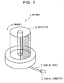
- Fig. 1 is a perspective view showing the configuration of a LAN antenna 1 in a preferred embodiment according to the present invention.
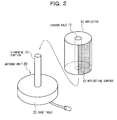
- Fig. 2 is a perspective view showing the configuration in which a reflector 10 is detached from the LAN antenna 1 in the preferred embodiment according to the present invention.
- a coaxial cable and a coaxial connector 3 to the antenna 1 are connected a coaxial cable and a coaxial connector 3.
- the LAN antenna 1 is constituted of the cylindrical reflector 10 and an antenna unit 20.
- a through hole 11 which is fitted to an elemental portion 21 in the antenna unit 20.
- a reflecting surface 12 is constituted of the surface (inclusive of a curved surface) formed by a conductor made of metal or the like.
- the antenna unit 20 includes the elemental portion 21 and a base table 22.
- the reflector 10 is detachably fitted to the antenna unit 20, and further, is configured in a turnable manner in a bearing direction.
- Figs. 3(a) and 3(b) are perspective views showing the configuration of an antenna element which is used inside of the LAN antenna 1 in the preferred embodiment according to the present invention.
- Fig. 3(a) shows an example in which the elemental portion 21 is constituted of a sleeve antenna.
- Fig. 3(b) shows an example in which the elemental portion 21 is constituted of a Brown antenna.
- the sleeve antenna 30 shown in Fig. 3(a) includes a radiation element 31 and a sleeve 33.
- RF power is supplied to the sleeve antenna 30 via a coaxial cable consisting of a coaxial center conductor 32, a dielectric 35 and a coaxial outer conductor 34.
- the sleeve 33 is connected to the coaxial outer conductor 34, and the radiation element 31 is connected to the coaxial center conductor 32.
- the Brown antenna 40 shown in Fig. 3(b) includes a radiation element 41 and a ground plane 43.
- RF power is supplied to the Brown antenna 40 via a coaxial cable consisting of a coaxial center conductor 42, a dielectric 45 and a coaxial outer conductor 44.
- the ground plane 43 is connected to the coaxial outer conductor 44, and the radiation element 41 is connected to the coaxial center conductor 42.
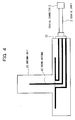
- Fig. 4 is a cross-sectional view showing the configuration of an antenna unit 20 in which a Brown antenna shown in Fig. 3(b) is used.
- the Brown antenna 40 is installed within a casing of the antenna unit 20.
- the coaxial center conductor 42, the dielectric 45 and the coaxial outer conductor 44 are connected to the coaxial connector 3 through the coaxial cable 2 from the side surface of the base table 22.
- Figs. 5 to 7 illustrate various examples of the reflector 10 in the preferred embodiment according to the present invention.
- Figs. 5(a) and 5(b) are views illustrating the details in the case in which the reflector 10 in the preferred embodiment according to the present invention has a cylindrical reflecting surface 12.
- Fig. 5(a) is a perspective view showing the reflector 10; in contrast, Fig. 5(b) is a top view showing the reflector 10.
- the reflecting surface 12 is constituted of a torus-like conductor, and is configured to be stuck around the reflector 10.
- the reflecting surface 12 covers an area at an angle ⁇ of 180° or less with respect to the center of the cylindrical reflector 10.
- Figs. 6(a) and 6(b) are views illustrating the details in the case in which the reflecting surface 12 of the reflector 10 in the preferred embodiment according to the present invention has a shape obtained by cutting a part of a circular cone.
- Fig. 6(a) is a perspective view showing the reflector 10; in contrast, Fig. 6(b) is a top view showing the reflector 10.
- the reflecting surface 12 shown in Figs. 6(a) and 6(b) approaches the center as it goes toward the bottom surface of the reflector 10.
- Figs. 7(a) to 7(f) are cross-sectional views illustrating the preferred embodiment in which the reflecting surface 12 has various shapes, taken on a plane indicated by A-A' of Fig. 6.
- Figs. 7(a) to 7(f) illustrate the relationship between the reflector 10 and the reflecting surface 12.
- Fig. 7(a) illustrates the example shown in Fig. 6.
- Fig. 7(b) illustrates the case in which a reflecting surface 102 reaches the wall surface of a cylinder on the way, wherein an elevation angle of the antenna can be increased in comparison with the example shown in Fig. 7(a).
- Fig. 7(c) illustrates the example in which a reflecting surface 103 shown in Fig. 7(b) reaches the wall surface of the cylinder, and then, extends upward on the wall surface thereof.
- Fig. 7(d) illustrates the example in which a reflecting surface 104 has a parabola or an arbitrary curve similar to the parabola in cross section.
- Fig. 7(e) illustrates the example in which a reflecting surface 105 has a step-like cross section.
- Fig. 7(f) illustrates the example in which a reflecting surface 106 has an inclined cross section leaning on the through hole bored at the center, to the contrary to the example illustrated in Fig. 7(a).
- the reflector 10 is detachably fitted to the antenna unit 20, and is configured in a turnable manner in a bearing direction.
- explanation will be made on the arrangement for obtaining a desired radiation pattern by the use of the configuration.
- Figs. 11(a) to 11(f) are views showing the shapes of the reflecting surfaces disposed in the reflector 10 in the preferred embodiment according to the present invention.
- Figs. 11(a) to 11(f) show various examples of the shape of the reflecting surface (the top views) in the case in which the prescribed radiation pattern in the bearing direction is obtained.
- the shapes of the reflecting surface disposed inside of the reflector 10 are devised as shown in Figs. 11(a) to 11(f).
- Fig. 11(a) shows the reflector 10 viewed from the top, wherein a reflecting surface 601 is constituted of a conductor made of a flat plate.
- Fig. 11(b) shows a reflecting surface 602 which is arranged in a L-shaped manner, and thus, forms a sort of corner reflector.
- a reflecting surface 603 shown in Fig. 11(c) consists of three pieces of flat conductors.
- a reflecting surface 604 shown in Fig. 11(d) consists of a W-shaped conductor. It has been known that when this type of W-shaped reflector is arranged, the radiation pattern becomes a sectorial beam (i.e., a fanned beam). (Paper entitled “Fanned Beam Antenna by Printed Dipole Array with Reflecting Plate", 1988, Spring National Meeting of the Institute of Electronic Information, 1-121)
- a reflecting surface 605 shown in Fig. 11(e) consists of a conductor made of a convex curved plate. This reflecting surface can form a radiation pattern having a broad beam in the bearing direction.
- a reflecting surface 606 shown in Fig. 11(f) consists of a conductor having a shape obtained by arbitrarily adjusting the arc of the reflector 10.
- a designer can design an antenna having a desired radiation pattern by arbitrarily combining the arrangement of the reflecting surface for controlling the direction of the elevation angle of the radiation pattern shown in any of Figs. 7(a) to 7(f) with the arrangement of the reflecting surface for controlling the bearing direction of the radiation pattern shown in any of Figs. 11(a) to 11(f).
- Figs. 8(a) and 8(b) are views illustrating examples of radiation patterns in the LAN antenna 1 in the preferred embodiment according to the present invention.
- the radiation pattern depends upon the shapes of the reflecting surfaces shown in Figs. 5 to 7.
- Fig. 8(a) schematically shows the radiation pattern in the case in which there is no reflector 10.
- Fig. 8(b) schematically shows the radiation pattern in the case in which the reflecting surface 12 is disposed as shown in Fig. 5.
- an upper view illustrates the radiation pattern on a horizontal plane; in contrast, a lower view illustrates the radiation pattern on a vertical plane.
- the antenna unit 20 is added with the reflector 10, so that the beam of the radiation pattern in the bearing direction can be limited in a single direction. Consequently, it is possible to prevent any interference with other access points in the LAN environment, to adjust the beam in a direction in which the condition is more optimum, or to select an access point with little access.
- Fig. 9 is a first view illustrating an example in which the LAN antenna 1 in the preferred embodiment according to the present invention is used in the office. By selecting the radiation pattern shown in Fig. 8(b), the beam of the antenna 1 can be directed to a desired access point antenna 200 illustrated in Fig. 9.
- Figs. 10(a) to 10(d) are cross-sectional views illustrating how the radiation pattern within an elevation angle surface is varied by using the reflector shown in Figs. 7(a), 7(d) and 7(f).
- a radiation pattern 504 symmetric in rotation, can be obtained as illustrated in Fig. 10(d).
- the antenna with the above-described radiation pattern is installed at a location illustrated in Fig. 9, it can communicate with two access points 200 and 201, thereby causing an interference.
- a radiation pattern illustrated in Fig. 10 (a) is a unidirectional beam 501 by the effect of the reflecting surface 101, thus preventing any interference with the right access point 201 illustrated in Fig. 9.
- a radiation pattern illustrated in Fig. 10(b) can provide a sharper beam 502 since the reflecting surface 104 forms the parabolic surface with respect to the surface of the elevation angle.
- the beam width ⁇ 2 of the beam 502 is narrower than the beam width ⁇ 1 of the beam 501, and therefore, the gain of the beam 502 becomes greater by the difference in beam width.
- a radiation pattern illustrated in Fig. 10(c) is effective in the case in which the access point is located somewhat under a terminal station. This is because the radiation pattern illustrated in Fig. 10(c) forms a downward beam 503 by the use of the reflecting surface 105.
- Figs. 12(a) and 12(b) are views illustrating the radiation patterns in Figs. 11(b) and 11(d), respectively.
- the reflector 10 functions as a corner reflector.
- a beam 610 illustrated in Fig. 12(a) radio waves reflected from the radiation elements 31 and 41 disposed at the center of the antenna are synthesized in the same phase in the same direction, thereby forming a unidirectional sharp beam.
- the reflecting surface 604 illustrated in Fig. 11(d) forms a fanned beam 620, as illustrated in Fig. 12(b).
- the above-described beam formation is effective in the environment as illustrated in Fig. 13.
- Fig. 13 is a second view illustrating a use example of the LAN antenna 1 in the preferred embodiment according to the present invention.
- Fig. 13 is a view illustrating the indoor LAN environment, as viewed from the top. In the situation in which there are four access points A to D and a terminal station is located at substantially the center of the four access points, communications cannot be excellently achieved by the adverse influence of an interference if the antenna directivity of the terminal station is non-directivity.
- the antenna 1 has a fanned beam like the beam 620 as illustrated in Fig. 13, the antenna 1 can communicate with only the access point A 301 without any interference with other access points.
- the use of either of the unidirectional sharp beam and the fanned beam is selected case by case, as illustrated in the two examples in Figs. 12(a) and 12(b).
- the terminal station in the case in which the terminal station is of a type which is seldom moved, such as a desktop personal computer, and further, the antenna for the LAN also is seldom moved, it is more advantageous to use the unidirectional antenna having a sharp beam for use.
- the terminal station in the case in which the terminal station is of a type which is frequently carried, such as a notebook personal computer, and further, the antenna connected to the outside also is frequently moved, the fanned beam is considered to be advantageous without any need of a severe direction adjustment.
- the strong directivity from the access point can be obtained under the LAN environment by additionally providing the reflector in the antenna and turning it, thus improving the throughput or BER (i.e., alleviating the interference with other access points or the like).
- the reflector is attached to or detached from the antenna, thus varying the antenna directivity.
- the antenna having the directivity in an arbitrary direction can be configured by attaching the reflector to the antenna; in contrast, the antenna having non-directivity can be configured by detaching the reflector from the antenna. Consequently, a more optimum access point can be selected under the LAN environment.
- the antenna according to the present invention can be used in the same manner as a normal LAN antenna even in the state in which no reflector is provided, and thus, it is excellent in general versatility.
- the radiation pattern can be freely formed in an arbitrary elevation angle or bearing direction according to the shape of the reflecting surface of the reflector.
- the board or sharp beam can be formed or the elevation angle can be changed.
- the bearing direction the board or sharp beam can be formed, or the fanned beam can be formed.
- the center of the beam can be readily changed by turning the reflector.
- a cylindrical reflector having a through hole in conformity with the shape of an elemental portion is fitted to the elemental portion in a LAN antenna in which the elemental portion encloses a linear conductor therein and projects from a base table, and further, the reflector is turned to be set at a position at which the directivity is formed in a specific direction.
- a flat plate or a curved plate forming a reflecting surface of the reflector is arbitrarily set, thus forming a desired radiation pattern of a beam.
Landscapes
- Engineering & Computer Science (AREA)
- Manufacturing & Machinery (AREA)
- Physics & Mathematics (AREA)
- Electromagnetism (AREA)
- Aerials With Secondary Devices (AREA)
- Variable-Direction Aerials And Aerial Arrays (AREA)
Abstract
Description
Claims (13)
- A LAN antenna having a directivity, comprising:a base;enclosure means for enclosing an antenna element projecting from said base;receiving means having a through hole for receiving said enclosure means; andreflecting means disposed on a side surface of said receiving means.
- A LAN antenna according to Claim 1, wherein said receiving means is detachably fitted to said enclosure means.
- A reflector for a LAN antenna having a base and enclosure means for enclosing an antenna element projecting from said base, said reflector comprising:receiving means having a through hole for receiving said enclosure means; andreflecting means disposed on a side surface of said receiving means.
- A reflector according to Claim 3, wherein said receiving means is detachably fittable to said enclosure means.
- A LAN antenna or a reflector therefor according to any preceding claim, wherein said enclosure means comprises a cylindrical member.
- A LAN antenna or reflector therefor according to any preceding claim, wherein said reflecting means comprising one or more flat and/or curved surfaces.
- A LAN antenna or reflector therefor according to any preceding claim, wherein said reflecting means is disposed in such a manner that a reflecting surface thereof rearwardly approaches a central axis of said reflecting means.
- A LAN antenna or reflector therefor according to any preceding claim, wherein said reflecting means is disposed in such a manner that a reflecting surface thereof forwardly approaches a central axis of said reflecting means.
- A LAN antenna or reflector therefor according to any preceding claim, wherein a reflecting surface of said reflecting means has a W-shape in cross section.
- A LAN antenna or reflector therefor according to any of Claims 1 to 8, wherein a reflecting surface of said reflecting means has a V-shape in cross section.
- A LAN antenna or reflector therefor according to any of Claims 1 to 8, wherein a reflecting surface of said reflecting means has a parabolic cross section.
- A LAN antenna or reflector therefor according to any of Claims 1 to 8, wherein said reflecting means is a parabolic reflector.
- A directional LAN antenna comprising an elongate antenna element and a reflector moveable angularly about a longitudinal axis of the antenna element.
Applications Claiming Priority (2)
| Application Number | Priority Date | Filing Date | Title |
|---|---|---|---|
| JP2001129663A JP2002325010A (en) | 2001-04-26 | 2001-04-26 | Lan antenna and its reflector |
| JP2001129663 | 2001-04-26 |
Publications (3)
| Publication Number | Publication Date |
|---|---|
| EP1256999A2 true EP1256999A2 (en) | 2002-11-13 |
| EP1256999A3 EP1256999A3 (en) | 2003-04-16 |
| EP1256999B1 EP1256999B1 (en) | 2007-06-13 |
Family
ID=18978154
Family Applications (1)
| Application Number | Title | Priority Date | Filing Date |
|---|---|---|---|
| EP02252953A Expired - Lifetime EP1256999B1 (en) | 2001-04-26 | 2002-04-25 | LAN antenna and reflector therefor |
Country Status (5)
| Country | Link |
|---|---|
| US (1) | US6816120B2 (en) |
| EP (1) | EP1256999B1 (en) |
| JP (1) | JP2002325010A (en) |
| AU (1) | AU783583B2 (en) |
| CA (1) | CA2383835C (en) |
Cited By (1)
| Publication number | Priority date | Publication date | Assignee | Title |
|---|---|---|---|---|
| US9899737B2 (en) | 2011-12-23 | 2018-02-20 | Sofant Technologies Ltd | Antenna element and antenna device comprising such elements |
Families Citing this family (24)
| Publication number | Priority date | Publication date | Assignee | Title |
|---|---|---|---|---|
| US6956534B2 (en) * | 2000-12-27 | 2005-10-18 | Cocomo Mb Communications, Inc. | Method and apparatus for improving antenna efficiency |
| US7190321B2 (en) * | 2003-07-31 | 2007-03-13 | Microsoft Corporation | Directional enhancement/range extending devices |
| JP4405514B2 (en) * | 2003-09-15 | 2010-01-27 | エルジー テレコム, リミテッド | Beam switching antenna system for mobile communication terminal and control method thereof |
| JP4551641B2 (en) * | 2003-09-29 | 2010-09-29 | シチズンホールディングス株式会社 | Portable electronic device with non-contact data communication function |
| US6977624B1 (en) | 2003-10-17 | 2005-12-20 | Szente Pedro A | Antenna directivity enhancer |
| TWI239121B (en) * | 2004-04-26 | 2005-09-01 | Ind Tech Res Inst | Antenna |
| US7158090B2 (en) * | 2004-06-21 | 2007-01-02 | Industrial Technology Research Institute | Antenna for a wireless network |
| SE528289C2 (en) * | 2004-07-09 | 2006-10-10 | Cellmax Technologies Ab | Antenna with coaxial connector |
| US7551680B2 (en) * | 2004-10-28 | 2009-06-23 | Interdigital Technology Corporation | Wireless communication method and apparatus for forming, steering and selectively receiving a sufficient number of usable beam paths in both azimuth and elevation |
| US20060094449A1 (en) * | 2004-10-28 | 2006-05-04 | Interdigital Technology Corporation | Method and apparatus for preventing communication link degradation due to the disengagement or movement of a self-positioning transceiver |
| US20060094485A1 (en) * | 2004-10-28 | 2006-05-04 | Interdigital Technology Corporation | Method and apparatus for preventing communication link degradation due to the detrimental orientation of a mobile station |
| US7176836B2 (en) * | 2005-03-31 | 2007-02-13 | Z-Com, Inc. | Antenna system designed to enhance power efficiency |
| JP4925891B2 (en) * | 2007-03-29 | 2012-05-09 | Dxアンテナ株式会社 | antenna |
| JP4877155B2 (en) * | 2007-08-24 | 2012-02-15 | 日本電気株式会社 | Antenna device and horizontal plane pattern switching method |
| US20090102733A1 (en) * | 2007-10-17 | 2009-04-23 | Motorola, Inc. | Antenna system and method for controlling an antenna pattern of a communication device |
| DE102008011350A1 (en) * | 2008-02-27 | 2009-09-03 | Loeffler Technology Gmbh | Apparatus and method for real-time detection of electromagnetic THz radiation |
| US8138986B2 (en) * | 2008-12-10 | 2012-03-20 | Sensis Corporation | Dipole array with reflector and integrated electronics |
| JP5769063B2 (en) * | 2011-04-15 | 2015-08-26 | 株式会社サクマアンテナ | antenna |
| JP5782661B2 (en) * | 2011-05-10 | 2015-09-24 | 株式会社サクマアンテナ | antenna |
| JP5473158B2 (en) * | 2011-07-29 | 2014-04-16 | 東芝テック株式会社 | Wireless communication system |
| JP2013219746A (en) * | 2012-03-15 | 2013-10-24 | Seiko Epson Corp | Sleeve antenna and wireless communication device |
| US20170194704A1 (en) * | 2016-01-05 | 2017-07-06 | John Mezzalingua Associates, LLC | Antenna having a beam interrupter for increased throughput |
| US11201392B2 (en) | 2017-04-17 | 2021-12-14 | Yokowo Co., Ltd. | Antenna apparatus |
| JP7097793B2 (en) * | 2018-10-17 | 2022-07-08 | 株式会社Kelk | Detection device |
Family Cites Families (18)
| Publication number | Priority date | Publication date | Assignee | Title |
|---|---|---|---|---|
| US2594839A (en) * | 1946-03-29 | 1952-04-29 | Us Sec War | Electrical apparatus |
| US2452767A (en) * | 1946-04-02 | 1948-11-02 | John D Kraus | Broad-band antenna |
| US3064258A (en) * | 1960-12-06 | 1962-11-13 | Hatkin Leonard | Directive antenna scanning and tracking device and applications thereof |
| US4195301A (en) * | 1977-08-01 | 1980-03-25 | Motorola, Inc. | Disc antenna feed for parabolic reflector |
| US5335366A (en) * | 1993-02-01 | 1994-08-02 | Daniels John J | Radiation shielding apparatus for a radio transmitting device |
| US6034638A (en) | 1993-05-27 | 2000-03-07 | Griffith University | Antennas for use in portable communications devices |
| US5373304A (en) * | 1993-05-27 | 1994-12-13 | Nolan; James F. | Cellular phone antenna reflector |
| JPH06350334A (en) | 1993-06-10 | 1994-12-22 | Mitsubishi Electric Corp | Antenna system |
| JPH0755862A (en) | 1993-08-18 | 1995-03-03 | Hitachi Ltd | Terminal reception status measuring device |
| JP3185513B2 (en) * | 1994-02-07 | 2001-07-11 | 株式会社村田製作所 | Surface mount antenna and method of mounting the same |
| JPH0884148A (en) | 1994-09-09 | 1996-03-26 | Canon Inc | Wireless LAN transceiver |
| DE4438435A1 (en) | 1994-10-28 | 1996-05-02 | Deutsche Telekom Mobil | Operating mobile terminal in mobile radio network |
| JPH08307142A (en) | 1995-04-27 | 1996-11-22 | Nippon Telegr & Teleph Corp <Ntt> | Bidirectional antenna and method for expanding frequency bandwidth of the antenna |
| JPH08321799A (en) | 1995-05-25 | 1996-12-03 | Nippondenso Co Ltd | Radio communication equipment and communication system |
| JPH08335825A (en) | 1995-06-09 | 1996-12-17 | Nippon Telegr & Teleph Corp <Ntt> | Antenna device |
| US6172650B1 (en) * | 1998-07-02 | 2001-01-09 | Kabushiki Kaisha Toyota Chuo Kenkyusho | Antenna system |
| JP2000183796A (en) | 1998-12-17 | 2000-06-30 | Ntt Mobil Communication Network Inc | Wireless communication device |
| DE29915174U1 (en) | 1999-08-30 | 1999-12-23 | Huang, I-Chung, Hsi Chih Chen, Taipeh | Electromagnetic wave absorption and shielding device for an antenna of a cellular phone |
-
2001
- 2001-04-26 JP JP2001129663A patent/JP2002325010A/en active Pending
-
2002
- 2002-04-24 US US10/128,427 patent/US6816120B2/en not_active Expired - Fee Related
- 2002-04-24 AU AU35628/02A patent/AU783583B2/en not_active Ceased
- 2002-04-24 CA CA002383835A patent/CA2383835C/en not_active Expired - Fee Related
- 2002-04-25 EP EP02252953A patent/EP1256999B1/en not_active Expired - Lifetime
Cited By (1)
| Publication number | Priority date | Publication date | Assignee | Title |
|---|---|---|---|---|
| US9899737B2 (en) | 2011-12-23 | 2018-02-20 | Sofant Technologies Ltd | Antenna element and antenna device comprising such elements |
Also Published As
| Publication number | Publication date |
|---|---|
| AU3562802A (en) | 2002-10-31 |
| AU783583B2 (en) | 2005-11-10 |
| US20020158807A1 (en) | 2002-10-31 |
| CA2383835C (en) | 2005-09-20 |
| JP2002325010A (en) | 2002-11-08 |
| EP1256999A3 (en) | 2003-04-16 |
| US6816120B2 (en) | 2004-11-09 |
| EP1256999B1 (en) | 2007-06-13 |
| CA2383835A1 (en) | 2002-10-26 |
Similar Documents
| Publication | Publication Date | Title |
|---|---|---|
| US6816120B2 (en) | LAN antenna and reflector therefor | |
| JP4072552B2 (en) | Thin embedded antenna architecture for wireless devices | |
| CN110915062B (en) | Base station antenna with reflector assembly with RF choke | |
| US7245259B2 (en) | Multiple antenna diversity on mobile telephone handsets, PDAs and other electrically small radio platforms | |
| EP1249893A2 (en) | Broadband antenna using semicircular radiator | |
| US7006053B2 (en) | Adjustable reflector system for fixed dipole antenna | |
| US10164325B1 (en) | Communication device | |
| US20070182642A1 (en) | Antenna apparatus | |
| US7079078B2 (en) | Patch antenna apparatus preferable for receiving ground wave and signal wave from low elevation angle satellite | |
| KR100647214B1 (en) | Antenna device | |
| GB2401994A (en) | Dual band antenna system with diversity | |
| EP0820116B1 (en) | Mobile radio antenna | |
| JP4431360B2 (en) | Multiband antenna | |
| US5539419A (en) | Antenna system for mobile communication | |
| JP2009130451A (en) | Antenna device | |
| JP2004201265A (en) | Planar inverted f antenna | |
| JP2002016427A (en) | Electronically controlled array antenna device | |
| Holda et al. | A novel, FSS-enhanced, pop-up card inspired corner reflector antenna | |
| JPH08335825A (en) | Antenna device | |
| US7250919B2 (en) | Antenna | |
| KR100304077B1 (en) | Antenna unit for suppression radio radiation to high angle of elevation | |
| JP7413464B2 (en) | Communication device | |
| JP2007174158A (en) | Ceiling embedded antenna | |
| KR100525313B1 (en) | A patch antenna using L-Probe feed with Shorting point | |
| JP2004282524A (en) | Reflector device for radio communication card |
Legal Events
| Date | Code | Title | Description |
|---|---|---|---|
| PUAI | Public reference made under article 153(3) epc to a published international application that has entered the european phase |
Free format text: ORIGINAL CODE: 0009012 |
|
| 17P | Request for examination filed |
Effective date: 20020511 |
|
| AK | Designated contracting states |
Kind code of ref document: A2 Designated state(s): AT BE CH CY DE DK ES FI FR GB GR IE IT LI LU MC NL PT SE TR |
|
| AX | Request for extension of the european patent |
Free format text: AL;LT;LV;MK;RO;SI |
|
| PUAL | Search report despatched |
Free format text: ORIGINAL CODE: 0009013 |
|
| AK | Designated contracting states |
Designated state(s): AT BE CH CY DE DK ES FI FR GB GR IE IT LI LU MC NL PT SE TR |
|
| AX | Request for extension of the european patent |
Extension state: AL LT LV MK RO SI |
|
| RIC1 | Information provided on ipc code assigned before grant |
Ipc: 7H 01Q 19/13 B Ipc: 7H 01Q 15/14 B Ipc: 7H 01Q 3/20 B Ipc: 7H 01Q 3/12 A |
|
| AKX | Designation fees paid |
Designated state(s): FR GB |
|
| 17Q | First examination report despatched |
Effective date: 20031204 |
|
| REG | Reference to a national code |
Ref country code: DE Ref legal event code: 8566 |
|
| GRAP | Despatch of communication of intention to grant a patent |
Free format text: ORIGINAL CODE: EPIDOSNIGR1 |
|
| GRAS | Grant fee paid |
Free format text: ORIGINAL CODE: EPIDOSNIGR3 |
|
| GRAA | (expected) grant |
Free format text: ORIGINAL CODE: 0009210 |
|
| AK | Designated contracting states |
Kind code of ref document: B1 Designated state(s): FR GB |
|
| REG | Reference to a national code |
Ref country code: GB Ref legal event code: FG4D |
|
| ET | Fr: translation filed | ||
| PLBE | No opposition filed within time limit |
Free format text: ORIGINAL CODE: 0009261 |
|
| STAA | Information on the status of an ep patent application or granted ep patent |
Free format text: STATUS: NO OPPOSITION FILED WITHIN TIME LIMIT |
|
| 26N | No opposition filed |
Effective date: 20080314 |
|
| PGFP | Annual fee paid to national office [announced via postgrant information from national office to epo] |
Ref country code: FR Payment date: 20120504 Year of fee payment: 11 Ref country code: GB Payment date: 20120425 Year of fee payment: 11 |
|
| GBPC | Gb: european patent ceased through non-payment of renewal fee |
Effective date: 20130425 |
|
| PG25 | Lapsed in a contracting state [announced via postgrant information from national office to epo] |
Ref country code: GB Free format text: LAPSE BECAUSE OF NON-PAYMENT OF DUE FEES Effective date: 20130425 |
|
| REG | Reference to a national code |
Ref country code: FR Ref legal event code: ST Effective date: 20131231 |
|
| PG25 | Lapsed in a contracting state [announced via postgrant information from national office to epo] |
Ref country code: FR Free format text: LAPSE BECAUSE OF NON-PAYMENT OF DUE FEES Effective date: 20130430 |