EP1256818A2 - Steerable transceiver unit for downhole acquisition in a formation - Google Patents
Steerable transceiver unit for downhole acquisition in a formation Download PDFInfo
- Publication number
- EP1256818A2 EP1256818A2 EP02252538A EP02252538A EP1256818A2 EP 1256818 A2 EP1256818 A2 EP 1256818A2 EP 02252538 A EP02252538 A EP 02252538A EP 02252538 A EP02252538 A EP 02252538A EP 1256818 A2 EP1256818 A2 EP 1256818A2
- Authority
- EP
- European Patent Office
- Prior art keywords
- reception
- transmission
- steering
- time
- remote sensor
- Prior art date
- Legal status (The legal status is an assumption and is not a legal conclusion. Google has not performed a legal analysis and makes no representation as to the accuracy of the status listed.)
- Granted
Links
- 230000015572 biosynthetic process Effects 0.000 title claims abstract description 47
- 230000005540 biological transmission Effects 0.000 claims abstract description 34
- 238000000034 method Methods 0.000 claims abstract description 24
- 238000005553 drilling Methods 0.000 claims abstract description 19
- 229910000859 α-Fe Inorganic materials 0.000 claims description 4
- 230000005284 excitation Effects 0.000 claims description 3
- 230000005672 electromagnetic field Effects 0.000 description 9
- 238000010586 diagram Methods 0.000 description 7
- 230000008901 benefit Effects 0.000 description 6
- 230000033001 locomotion Effects 0.000 description 6
- 238000004891 communication Methods 0.000 description 5
- 230000035699 permeability Effects 0.000 description 5
- 238000012546 transfer Methods 0.000 description 5
- 239000004020 conductor Substances 0.000 description 4
- 230000006870 function Effects 0.000 description 4
- 230000002068 genetic effect Effects 0.000 description 4
- 238000005457 optimization Methods 0.000 description 4
- 230000008569 process Effects 0.000 description 4
- 230000000694 effects Effects 0.000 description 3
- 238000005259 measurement Methods 0.000 description 3
- 238000012986 modification Methods 0.000 description 3
- 230000004048 modification Effects 0.000 description 3
- 230000035515 penetration Effects 0.000 description 3
- 230000008859 change Effects 0.000 description 2
- 238000013461 design Methods 0.000 description 2
- 238000011161 development Methods 0.000 description 2
- 238000009826 distribution Methods 0.000 description 2
- 239000002184 metal Substances 0.000 description 2
- 239000000203 mixture Substances 0.000 description 2
- 239000011435 rock Substances 0.000 description 2
- 238000004458 analytical method Methods 0.000 description 1
- 238000013459 approach Methods 0.000 description 1
- 238000010276 construction Methods 0.000 description 1
- 230000008878 coupling Effects 0.000 description 1
- 238000010168 coupling process Methods 0.000 description 1
- 238000005859 coupling reaction Methods 0.000 description 1
- 238000005516 engineering process Methods 0.000 description 1
- 238000011156 evaluation Methods 0.000 description 1
- 238000009472 formulation Methods 0.000 description 1
- 238000004519 manufacturing process Methods 0.000 description 1
- 230000007246 mechanism Effects 0.000 description 1
- 239000003129 oil well Substances 0.000 description 1
- 239000003209 petroleum derivative Substances 0.000 description 1
- 238000003825 pressing Methods 0.000 description 1
- 239000003380 propellant Substances 0.000 description 1
- 238000004080 punching Methods 0.000 description 1
- 230000004044 response Effects 0.000 description 1
- 230000000153 supplemental effect Effects 0.000 description 1
- 238000012360 testing method Methods 0.000 description 1
Images


Classifications
-
- G—PHYSICS
- G01—MEASURING; TESTING
- G01V—GEOPHYSICS; GRAVITATIONAL MEASUREMENTS; DETECTING MASSES OR OBJECTS; TAGS
- G01V3/00—Electric or magnetic prospecting or detecting; Measuring magnetic field characteristics of the earth, e.g. declination, deviation
- G01V3/18—Electric or magnetic prospecting or detecting; Measuring magnetic field characteristics of the earth, e.g. declination, deviation specially adapted for well-logging
- G01V3/26—Electric or magnetic prospecting or detecting; Measuring magnetic field characteristics of the earth, e.g. declination, deviation specially adapted for well-logging operating with magnetic or electric fields produced or modified either by the surrounding earth formation or by the detecting device
- G01V3/28—Electric or magnetic prospecting or detecting; Measuring magnetic field characteristics of the earth, e.g. declination, deviation specially adapted for well-logging operating with magnetic or electric fields produced or modified either by the surrounding earth formation or by the detecting device using induction coils
-
- G—PHYSICS
- G01—MEASURING; TESTING
- G01V—GEOPHYSICS; GRAVITATIONAL MEASUREMENTS; DETECTING MASSES OR OBJECTS; TAGS
- G01V11/00—Prospecting or detecting by methods combining techniques covered by two or more of main groups G01V1/00 - G01V9/00
- G01V11/002—Details, e.g. power supply systems for logging instruments, transmitting or recording data, specially adapted for well logging, also if the prospecting method is irrelevant
-
- G—PHYSICS
- G01—MEASURING; TESTING
- G01V—GEOPHYSICS; GRAVITATIONAL MEASUREMENTS; DETECTING MASSES OR OBJECTS; TAGS
- G01V3/00—Electric or magnetic prospecting or detecting; Measuring magnetic field characteristics of the earth, e.g. declination, deviation
- G01V3/18—Electric or magnetic prospecting or detecting; Measuring magnetic field characteristics of the earth, e.g. declination, deviation specially adapted for well-logging
- G01V3/34—Transmitting data to recording or processing apparatus; Recording data
Definitions
- This invention relates generally to the drilling of wells, such as for the production of petroleum products, and, more particularly, the acquisition of subsurface formation data such as formation pressure, formation permeability and the like.
- a trip typically involves removing the drill string from the well bore, running a formation tester into the well bore to acquire the formation data, and, after retrieving the formation tester, running the drill string back into the well bore for further drilling. Because "tripping the well” uses significant amounts of expensive rig time, it is typically done under circumstances where the formation data is absolutely needed, during a drill bit change, or when the drill string is being removed for some other drilling related reason.
- the data transfer will typically occur, at least some of the time, during drilling operations.
- the drill string in which the drill collar is installed will both rotate and translate during drilling operations.
- the remote sensor by virtue of its deployment into the formation, will neither translate nor rotate in any significant sense.
- the present invention is directed to resolving, or at least reducing, one or all of the problems mentioned above.
- the invention includes a method and apparatus for collecting data downhole in a well bore, even during drilling operations.
- the apparatus generally comprises an antenna and some associated electronic circuitry.
- the antenna includes a plurality of arrayed transceiver elements and the electronic circuitry steers transmission or reception through the antenna by controlling the application of power to the array elements.
- a transceiver unit containing such an antenna is positioned proximate a remote sensor placed into a formation. An electromagnetic signal is then steered to communicate with the remote sensor over a wireless link.
- FIG. 1 depicts one particular embodiment of a drill collar 100.
- the drill collar 100 comprises but one component of a drill string (not otherwise shown) for drilling a well bore 105.
- the drill collar 100 is provided with a sonde section 110 including a power cartridge 200, shown in FIG. 2, incorporating the transmitter/receiver circuitry 300 of FIG. 3.
- the drill collar 100 includes a pressure gauge 205 whose pressure sensor 210 is exposed to borehole pressure in the well bore 105 via a drill collar passage 215.
- the pressure gauge 205 senses ambient pressure at the depth of a selected subsurface formation and is used to verify pressure calibration of remote sensors.
- Electronic signals (not shown) representing ambient well bore pressure are transmitted via the pressure gauge 205 to the circuitry of the power cartridge 200.
- the power cartridge 200 then performs a pressure calibration of a remote sensor 115, shown best in FIG. 1, being deployed at that particular well bore depth.
- the drill collar 100 is also provided with one or more remote sensor receptacles 120, also shown in FIG. 1.
- Each sensor receptacle 120 contains a remote sensor 115 for positioning within a selected subsurface formation of interest intersected by the well bore 105.
- the remote sensor 115 is positioned, in this particular embodiment, while the well bore 105 is being drilled.
- the remote sensor 115 may be previously emplaced and used in conjunction with the steerable transceiver unit of the present invention. In such embodiments, efforts will typically need to be made to identify the location of the remote sensor 115, as is discussed more fully below.
- the remote sensors 115 are encapsulated "intelligent" sensors that are moved from the drill collar 100 to a position within the formation surrounding the well bore 105.
- the remote sensors 115 sense formation characteristics such as pressure, temperature, rock permeability, porosity, conductivity, and dielectric constant, among others.
- the remote sensors 115 are appropriately encapsulated in a sensor housing of sufficient structural integrity to withstand damage during movement from the drill collar 100 into laterally embedded relation with the subsurface formation surrounding the well bore 105.
- FIG. 1 illustrates a single remote sensor 115 embedded in a formation in a roughly perpendicular orientation relative to the well bore 105 and, hence, the drill collar 100.
- Sensor deployment can be achieved utilizing one or more of the following: (1) drilling into the borehole wall 125 and placing the remote sensor 115 into the formation; (2) punching/pressing the encapsulated remote sensors 115 into the formation with a hydraulic press or other mechanical penetration assembly; or (3) shooting the remote sensors 115 into the formation by utilizing propellant charges. Any of these techniques are suitable, depending on the implementation. For instance, although the illustrated embodiment uses a hydraulic mechanism (discussed more fully below), an alternative embodiment emplaces the remote sensor 115 ballistically.
- FIG. 2 illustrates a hydraulically energized ram 220 employed for this purpose in the illustrated embodiment.
- the ram 220 deploys the remote sensor 115 and causes its penetration into the subsurface formation to a sufficient position outwardly from the borehole 130 of the well bore 105 so that it can sense selected characteristics of the formation.
- the drill collar 100 is provided with an internal cylindrical bore 222 within which is positioned a piston element 225 having the ram 220 disposed in driving relation with the encapsulated remote intelligent sensor 115.
- the piston element 225 is exposed to hydraulic pressure communicated to a piston chamber 230 from a hydraulic system 235 via a hydraulic supply passage 240.
- the hydraulic system 235 is selectively activated by the power cartridge 200 so that the remote sensor 115 can be calibrated with respect to ambient borehole pressure at formation depth, as described above.
- the remote sensor 115 can then be moved from the receptacle 120 into the formation beyond the borehole wall 125 so that formation pressure characteristics will be free from borehole effects.
- the power cartridge 200 of the drill collar 100 includes a transceiver unit 305 driven by a transceiver power drive 310 (e . g ., a power amplifier) at a frequency determined by an oscillator 315.
- the transceiver unit 305 will receive signals that will be transmitted to the sonde section 110 of the drill collar 100 by the remote sensor 115 as will be explained hereinbelow. Note that the 2:1 ratio is not necessary to the practice of the invention, and that other ratios may be employed.
- the transceiver unit 305 includes an arrayed antenna 325 and one or more transceivers 330, depending on the implementation, which are also discussed more fully below.
- FIG. 4A, FIG. 4B, FIG. 4C, and FIG. 4D illustrate different implementations of the arrayed antenna 325 of the power cartridge 200.
- Each of these implementations employs multiple transceiver elements 400.
- each transceiver element 400 comprises a coil 405 wound upon a ferrite core 410 in a groove 415 in the ferrite core 410.
- FIG. 4B illustrates an implementation wherein multiple coils 420 are arrayed upon a flexible insulating board 425 that can be wrapped around the interior of the drill collar 100. Power is supplied to each coil 420 by a respective feed terminal 430.
- the coils 420 may be of any shape known to the art.
- the embodiment of FIG. 4C is much the same as the embodiment of FIG.
- FIG. 4D illustrates an implementation wherein multiple slot antennae 440 are arrayed in a metal sheet 445.
- the metal sheet 445 may be conformal to the drill collar 100.
- each of these implementations may be generically referred to as arrayed transceiver elements including (i.e., the coils 405, the coils 420, the coils 435, and the slot antennae 440, respectively) since they can all be used in both transmitting and receiving signals.
- arrayed transceiver elements including (i.e., the coils 405, the coils 420, the coils 435, and the slot antennae 440, respectively) since they can all be used in both transmitting and receiving signals.
- FIG. 4A, FIG. 4B, FIG. 4C, and FIG. 4D may be combined in some embodiments, such as that shown in FIG. 5B and discussed below.
- the array elements 400 may be configured in series, in parallel, or in a combination of in series and in parallel, depending on the implementation. This configuration can be hardwired or controlled by the transceiver power drive 310, as discussed further below in connection with FIG. 5A, FIG. 5B.
- the implementations of the transmitter/receiver elements illustrated in FIG. 4A, FIG. 4B, FIG. 4C, and FIG. 4D are highly scalable in the axial direction. However, certain difficulties arise in exciting an axially long antenna including several coils or slots. In particular, the power requirement can become a limiting factor. This difficulty can be overcome by exciting only a subset of coils or slots at a given time in applications requiring large axial coverage. This design constraint can be realized in a manner discussed more fully below in connection with FIG. 5A, FIG. 5B.
- the configuration of the array antenna 325 affects the generation and propagation of the electromagnetic field.
- FIG. 4A which will produce an axisymmetric electromagnetic field.
- the objective is to find the direction p k of current in each coil and the corresponding location d k that maximize the functional, J (p,d), which is a measure of homogeneity and amplitude of magnetic field where the first term on the right-hand side of Eq. (1) maximizes the mean value of the field and the second term inside the bracket ensures uniformity along the axial direction. From Eq. (1) it is clear that while the distance ( d ) between coils 405 is a continuous variable, the direction of current ( p ) flowing through them can assume only two values - positive or negative.
- One particular implementation uses a genetic algorithm employing a random search method and works with discreet variables for optimization.
- Commercially available genetic algorithms such as the GEATbx genetic and evolutionary algorithm toolbox for use with MATLABTM, are suitable.
- Positive constants C 1 and C 2 are selected to give appropriate weight to each term. Since the genetic algorithm maximizes the objective function, a sufficiently large positive constant C 3 is chosen to make the term in the bracket a positive quantity.
- These constants are empirically selected, primarily based on the requirements of electronic circuits and the signal to noise ratio. For instance, there is a lower limit on the signal level that can be detected by the receiver.
- the magnetic field is computed at every point in the space v . This involves first generating a base field for a single coil 405 and then using superposition to compute the total field for the entire arrayed antenna 325. Although superposition may not hold exactly, it is a reasonable assumption for low-frequency applications if the space v is not too close to the drill collar 100. The total field computation by superposition greatly reduces the computation time.
- a finite element method (“FEM”) analysis of the whole arrayed antenna 325 is performed. The embodiment illustrated in FIG.
- 4A achieves a uniform field whose magnitude depends largely on the availability of power, which is quite restricted for the environment in which well-logging tools usually operate. Note that a well-logging tool often operates at a typical depth of about 5 kilometers and has to withstand high temperature (around 175°C) and high pressure (typically 20,000 psi) environment.
- FIG. 5A and FIG. 5B illustrate how the antenna array elements 500 can be excited individually to produce a desired spatial distribution of electromagnetic fields. Furthermore, these spatial distributions can be changed in real time to keep the collar 100 and the antenna 605 of the remote sensor 115 in constant communication when there is a relative motion between the two antennas.
- the antenna array 505 is axisymmetric, e . g ., such as the embodiment of FIG. 4A discussed above. For this case, only axial controllability of the arrayed antenna 505 is required. That is, given the relative position of the drill collar 100 and the antenna 605 of the remote sensor 115, an appropriate subset of the array elements 500 may be energized using an array 510 of switchable elements, such as switches, 515.
- FIG. 5B illustrates the general case for driving the array elements 500.
- both angular as well as axial controllability of excitation can be achieved.
- the array elements 500 are configured in series.
- the individual array elements can be connected together in series or in parallel or a combination thereof, with some (slight) modification to the embodiment of FIG. 5A.
- the array elements 500 produce an axisymmetric electromagnetic field, and so only axial control is needed, as was mentioned above.
- the array elements 500 are coils wound upon a ferrite core (not shown) as in the embodiment of FIG. 4A.
- the switches 515 provide this control by controlling power to the individual array elements 500.
- the switches 515 are, in turn, controlled by electronic control logic 520. Once the control logic 520 determines the pattern in which it wishes to vary the field, it opens and closes the switches 515 to affect the variations. This determination may be made in real-time, or may be predetermined. For instance, if the primary concern is providing adequate power to all of the array elements 500, the switches 515 may be operated to provide power to them sequentially in series. If the concern is to obtain data from multiple remote sensors 115 through some, but not all, of the array elements, additional selectivity can be shown in which array elements 500 receive power.
- FIG. 5B the embodiment shown therein includes the array elements 500, the array 510 of switches 515, and the control logic 520 of the embodiment in FIG. 5A.
- the embodiment of FIG. 5B exerts axial control over the electromagnetic field in the same manner as described above for the embodiment of FIG. 5A.
- the embodiment of FIG. 5B also includes several layers of array elements 525.
- the array elements 525 may be coils formed in a sheet 530 conformed to the internal surface of the drill collar 100, as in the embodiments of FIG. 4B and FIG. 4C discussed above. Power to the array elements 525 is controlled by a second array 535 of switches 540, whose operation is controlled by the control logic 545.
- control logic 545 can be combined with that of the control logic 520 to create a single control logic block.
- the control logic 545 determines the pattern in which it wishes to vary the field, it opens and closes the switches 540 to effect the variations. This determination may be made in real-time, or may be predetermined, as in the case of axial variations.
- these particular embodiments employ a single transceiver 550 for axial control and a plurality of transceivers 555, one for each level of array elements 525, for angular control.
- the antenna 560 consists of an array of magnetic loop antennas 500, 525, each of which is an "array element" as was discussed above.
- the loops 525 provide a field mainly in a radial or angular orientation and the loops 500 provide a field mainly in an axial direction.
- the loops 500, 525 can be configured by the switches 515, 540 thought the control logic 520, 545. In this manner, virtually any combination of loops 500, 525 can operate in series or in parallel, be switched on or off, or operate with reversed polarity.
- the antenna 560 can therefore be configured to maximize a field in a particular direction and will be more sensitive to receive a field from that particular direction.
- each collar transceiver 555 consists of a transmitter 565, a receiver 570, and a duplexer 575.
- the transceivers 555 detect the tones through the receivers 570 via the arrayed antenna 560 (shown in FIG. 5B ) and the duplexer 575, which are then forwarded to the processor 580.
- the processor 580 is a digital signal processor ("DSP") in the illustrated embodiment.
- the processor 580 then calculates the position of the remote sensor 115 using a triangulation technique. This position information is used for a proper switch selection in an initial configuration phase and later for calculating the amplitude of the different radial loops 525.
- the transmitter 565 consists of a power amplifier.
- the power amplifier 585 is driven from a programmable oscillator (not shown).
- the supply voltage (also not shown) of each power amplifier 585 is also programmable.
- the output amplitude of each transceiver 555 is programmed via the supply voltage. For better efficiency, the supply voltage is generated with programmable switching supplies.
- the output amplitude of the transmitters 565 is varied via the supply voltage by pulse width modulation ("PWM") to steer the signal in the right direction by a superposition fields of different amplitudes generated by several separately driven transmitter loops.
- PWM pulse width modulation
- the electronic circuitry of the remote "smart sensor" 115 is shown by a block diagram generally at 600 and includes at least one transmitter/receiver coil 605 or RF antenna, with the receiver thereof providing an output 610 from a detector 615 to a controller circuit 620.
- the controller circuit 620 is provided with one of its controlling outputs 625 being fed to a pressure gauge 630 so that gauge output signals will be conducted to an analog-to-digital converter (“ADC")/memory 635, which receives signals from the pressure gauge via a conductor 640 and also receives control signals from the controller circuit 620 via a conductor 645.
- ADC analog-to-digital converter
- a battery 650 is provided within the remote sensor circuitry 600 and is coupled with the various circuitry components of the sensor 115 by power conductors 655, 670 and 675.
- a memory output 680 of the ADC/memory circuit 635 is fed to a receiver coil control circuit 685.
- the receiver coil control circuit 685 functions as a driver circuit via conductor 690 for transmitter/receiver coil 605 to transmit data to the transmitter/receiver circuitry 300.
- the transceiver unit 305 shown in FIG. 3 , is also used as a receiver.
- the remote sensor 115 is located in close proximity for optimum transmission between the drill collar 100 and the remote sensor 115.
- the remote sensor 115 in operation, once the remote sensor 115 is emplaced, it begins collecting data.
- the remote sensor 115 includes a timer that periodically initiates a power up of the electronic circuitry 600 (shown in FIG. 6). The remote sensor 115 then acquires data, stores it in the ADC/memory 635, and goes back to sleep.
- the collar transmitter 700 which contains a power amplifier (not shown), sends a wakeup tone to the remote sensor 115 through the arrayed antenna 325.
- the wakeup tone is transmitted at a frequency close to the resonant frequency of the remote sensor 115.
- the remote sensor 115 receives the tone through its antenna 605 if the arrayed antenna 325 is close enough, detects the received signal through the receiver wakeup electronics 705, and wakes up if the signal is of the right frequency. The remote sensor 115 then sends an acknowledge signal to the collar transmitter 700 and waits to receive a command.
- the remote sensor 115 When awakened by the collar transmitter 700, the remote sensor 115 is capable of receiving and executing a number of commands, such as acquire data, transmit data, memory read, and memory write. Most commonly, the collar transmitter 700 will instruct the remote sensor 115 to transmit data.
- the remote sensor 115 transmits measurement data from the transmitter 710 through the antenna 605 to the transmitter/receiver circuitry 300 and goes back to sleep.
- the receiver 715 in the transmitter/receiver circuitry 300 amplifies, demodulates and decodes the data.
- a duplexer 720 in the collar electronics protects the receiver 715 in the collar 100.
- the arrayed antenna 325 in the collar 100 is tuned in resonance to the transmit frequency of the remote sensor 115.
- the transmitter/receiver circuitry 300 also contains, in addition to the resonance frequency tuning circuit 725, the array of switches (shown in FIG. 5A, FIG. 5B ) for the selection of the active antenna array elements 400 and their polarity.
- the drill collar 100 is positioned in close proximity of the remote sensor 115.
- the drill collar 100 is actually used to emplace the remote sensor 115, in which case the drill collar 100 will be proximate the remote sensor 115. If the remote sensor 115 was previously emplaced, its location may be determined from records regarding its emplacement.
- the transceiver unit 305 can be used to locate the remote sensor 115 by bobbing the drill collar 100 in the well bore 105. An electromagnetic wave is transmitted from the transmitter/receiver circuitry 300 in the drill collar 100 to 'switch on' the remote sensor 115 and to induce the remote sensor 115 to send back an identifying coded signal.
- This "handshaking" process can be used to identify the location of the remote sensor 115, since the receipt of the handshaking signal from the remote sensor 115 will indicate the drill collar 100 is positioned sufficiently proximate to the location of the remote sensor 115.
- the location of the remote sensor 115 must then be tracked once the location is identified. Communication between the drill collar 100 and the remote sensor 115 will typically occur during drilling operations, although this is not necessary to the practice of the invention. There typically will therefore be some degree of translational and rotational movement of the transceiver unit 305 relative to the remote sensor 115, and this movement should be tracked. This can be accomplished by identifying the array elements 400, or groups of array elements 400, receiving the handshaking signal from the remote sensor 115 over time, assuming the array elements 400 are arrayed both axially and angularly. From this information, the relative positions of the transceiver 305 elements and the remote sensor 115 can be extrapolated. Once the relative positions are extrapolated, control logic ( e .
- control logic 520, 545 in FIG. 5A and FIG. 5B can determine how it wishes to vary the electromagnetic field generated by the transceiver unit 305 to maintain continuous contact between the drill collar 100 and the remote sensor(s) 115.
- the distance from the well bore 105 that the remote sensor 115 is emplaced into the formation should also be determined.
- One approach to this determination is to triangulate from the phase differences of the handshaking signal as received at three or more of the array elements 400. Note that the distance determination should follow the location identification.
- One advantage to identifying the location and emplacement distance of the remote sensor 115 and tracking its location is that it permits the transceiver unit to focus the electromagnetic field that it generates in the direction of the remote sensor 115.
- This advantage will not be appreciated in embodiments where the arrayed antenna 315 generates an axisymmetric field, however, since the field is ⁇ by definition ⁇ axisymmetric.
- the realization of this advantage is not necessary to the practice of the invention. This is true even in embodiments where the generated electromagnetic field is not axisymmetric. Note, however, that in embodiments where this is performed, it is performed in real time and can be implemented during drilling operations.
- the handshaking process initiates the electronics of the remote sensor 115 to go into the acquisition and transmission mode, and pressure data and other data representing selected formation characteristics, as well as the sensor's identification code, are obtained at the level of the remote sensor 115.
- the remote sensor 115 might continuously acquire data even while in a sleep state, such that it will enter a transmission mode only, on awaking.
- pressure gauge data pressure and temperature
- the electronics of the remote sensor 115 convert the data into one or more serial digital signals. This digital signal or signals, as the case may be, is transmitted from the remote sensor 115 back to the drill collar 100 via the transmitter/receiver circuitry 300.
- the transmitter/receiver circuitry 300 located within the drill collar 100 is powered by the transceiver power drive 310.
- An electromagnetic wave is transmitted from the drill collar 100 at a frequency determined by the oscillator 315.
- the frequency can be selected within the range from 100 KHz up to 500 MHz.
- the receiver coil 605 located within the remote sensor 115 will radiate back an electromagnetic wave at twice the original frequency by means of the receiver coil control circuit 685 and the coil 605.
- an eight-turn coil was designed.
- a base field was generated using a commercially available FEM code.
- the FEM code was validated by solving a simpler geometry using an analytical solution for coil response in a cylindrically layered medium.
- the plot indicates good uniformity of the voltage (and hence, the magnetic field) in the optimization region.
Landscapes
- Life Sciences & Earth Sciences (AREA)
- Physics & Mathematics (AREA)
- General Life Sciences & Earth Sciences (AREA)
- General Physics & Mathematics (AREA)
- Geophysics (AREA)
- Remote Sensing (AREA)
- Engineering & Computer Science (AREA)
- Environmental & Geological Engineering (AREA)
- Geology (AREA)
- Electromagnetism (AREA)
- Arrangements For Transmission Of Measured Signals (AREA)
- Geophysics And Detection Of Objects (AREA)
- Selective Calling Equipment (AREA)
- Variable-Direction Aerials And Aerial Arrays (AREA)
Abstract
Description
- This invention relates generally to the drilling of wells, such as for the production of petroleum products, and, more particularly, the acquisition of subsurface formation data such as formation pressure, formation permeability and the like.
- In oil well description services, one part of the standard formation evaluation characteristics is concerned with the reservoir pressure and the permeability of the reservoir rock. Present day operations obtain these characteristics either through wireline logging via a "formation tester" tool or through drill stem tests. Both types of measurements are available in "open-hole" or "cased-hole" applications, and require a supplemental "trip". A trip typically involves removing the drill string from the well bore, running a formation tester into the well bore to acquire the formation data, and, after retrieving the formation tester, running the drill string back into the well bore for further drilling. Because "tripping the well" uses significant amounts of expensive rig time, it is typically done under circumstances where the formation data is absolutely needed, during a drill bit change, or when the drill string is being removed for some other drilling related reason.
- On the other hand, during well drilling activities, the availability of reservoir formation data on a "real time" basis is a valuable asset. Real time formation pressure obtained while drilling will allow a drilling engineer or driller to make decisions concerning changes in drilling mud weight and composition as well as penetration characteristics at a much earlier time to thus promote the selected aspects of drilling. The availability of real time reservoir formation data is also desirable to enable precision control of drill bit weight in relation to formation pressure changes and changes in permeability so that the drilling operation can be carried out with greater efficiency.
- It is therefore desirable to acquire various formation data from a subsurface zone of interest while the drill string is present within the well bore. This eliminates or minimizes the need for tripping the well solely to run formation testers into the well bore to identify formation characteristics such as pressure, temperature, permeability, etc. One such technique is disclosed in United States Letters Patent 6,028,534, issued to Schlumberger Technology Corporation on February 22, 2000, as assignee of the named inventors Ciglenec, et al. This patent is commonly assigned herewith. In this technique, a remote sensor containing sensor instrumentation and associated electronics is deployed into a formation. The remote sensor also contains an antenna and a battery to communicate with a host antenna on the drill collar while the drill string is in the well bore. Once deployed, the remote sensor measures one or more of the formation's characteristics. After the measurement is complete, the data is stored in the remote sensor. A wireless communication channel is subsequently established between the remote sensor and the drill collar for data transfer.
- The data transfer will typically occur, at least some of the time, during drilling operations. The drill string in which the drill collar is installed will both rotate and translate during drilling operations. However, the remote sensor, by virtue of its deployment into the formation, will neither translate nor rotate in any significant sense. Thus, during the data transfer, there may be rotational as well as translational movement of the collar antenna with respect to the remote antenna. Consequently, there frequently are two main aspects in regards to electromagnetic coupling between the collar antenna and the remote antenna ― locating the remote sensor, and maintaining the communication channel for the entire data transfer once the remote sensor has been found.
- The present invention is directed to resolving, or at least reducing, one or all of the problems mentioned above.
- The invention includes a method and apparatus for collecting data downhole in a well bore, even during drilling operations. The apparatus generally comprises an antenna and some associated electronic circuitry. The antenna includes a plurality of arrayed transceiver elements and the electronic circuitry steers transmission or reception through the antenna by controlling the application of power to the array elements. In operation, a transceiver unit containing such an antenna is positioned proximate a remote sensor placed into a formation. An electromagnetic signal is then steered to communicate with the remote sensor over a wireless link.
- The invention may be understood by reference to the following description taken in conjunction with the accompanying drawings, in which like reference numerals identify like elements, and in which:
- FIG. 1 is a diagram of a drill collar positioned in a borehole and equipped with a steerable transceiver unit in accordance with the present invention;
- FIG. 2 is a schematic illustration of the steerable transceiver unit of the drill collar of FIG. 1 showing a hydraulically energized system for emplacing a remote sensor from the borehole into a selected subsurface formation;
- FIG. 3 schematically diagrams the electronic circuitry of the steerable transceiver unit of the drill collar of FIG. 1 for receiving data signals from and transmitting signals to the remote sensor;
- FIG. 4A, FIG. 4B, FIG. 4C, and FIG. 4D illustrate alternative implementations of the arrayed antenna of the steerable transceiver unit of FIG. 3;
- FIG. 5A and FIG. 5B illustrate in electronic block diagrams the electronics employed to steer the transmission from and reception by the transceiver of FIG. 3 in accordance with the present invention in two different implementations;
- FIG. 5C illustrates in an electronic block diagram a portion of the electronic controls in the embodiment of FIG. 5B;
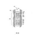
- FIG. 6 is an electronic block diagram schematically illustrating the electronics of a remote sensor;
- FIG. 7 is a block diagram conceptually illustrating operation of the steerable transceiver unit in conjunction with the remote sensor in accordance with the present invention; and
- FIG. 8 graphs the measured voltage received by the remote sensor upon the introduction as a function of coil location in one particular implementation.
-
- While the invention is susceptible to various modifications and alternative forms, specific embodiments thereof have been shown by way of example in the drawings and are herein described in detail. It should be understood, however, that the description herein of specific embodiments is not intended to limit the invention to the particular forms disclosed, but on the contrary, the intention is to cover all modifications, equivalents, and alternatives falling within the spirit and scope of the invention as defined by the appended claims.
- Illustrative embodiments of the invention are described below. In the interest of clarity, not all features of an actual implementation are described in this specification. It will of course be appreciated that in the development of any such actual embodiment, numerous implementation-specific decisions must be made to achieve the developers' specific goals, such as compliance with system-related and business-related constraints, which will vary from one implementation to another. Moreover, it will be appreciated that such a development effort, even if complex and time-consuming, would be a routine undertaking for those of ordinary skill in the art having the benefit of this disclosure.
- FIG. 1 depicts one particular embodiment of a
drill collar 100. Thedrill collar 100 comprises but one component of a drill string (not otherwise shown) for drilling a well bore 105. Thedrill collar 100 is provided with asonde section 110 including apower cartridge 200, shown in FIG. 2, incorporating the transmitter/receiver circuitry 300 of FIG. 3. As shown in FIG. 2, thedrill collar 100 includes apressure gauge 205 whosepressure sensor 210 is exposed to borehole pressure in the well bore 105 via adrill collar passage 215. Thepressure gauge 205 senses ambient pressure at the depth of a selected subsurface formation and is used to verify pressure calibration of remote sensors. Electronic signals (not shown) representing ambient well bore pressure are transmitted via thepressure gauge 205 to the circuitry of thepower cartridge 200. Thepower cartridge 200 then performs a pressure calibration of aremote sensor 115, shown best in FIG. 1, being deployed at that particular well bore depth. - The
drill collar 100 is also provided with one or moreremote sensor receptacles 120, also shown in FIG. 1. Eachsensor receptacle 120 contains aremote sensor 115 for positioning within a selected subsurface formation of interest intersected by thewell bore 105. As will be discussed further below, theremote sensor 115 is positioned, in this particular embodiment, while the well bore 105 is being drilled. Note, however, that theremote sensor 115 may be previously emplaced and used in conjunction with the steerable transceiver unit of the present invention. In such embodiments, efforts will typically need to be made to identify the location of theremote sensor 115, as is discussed more fully below. - The
remote sensors 115 are encapsulated "intelligent" sensors that are moved from thedrill collar 100 to a position within the formation surrounding thewell bore 105. Theremote sensors 115 sense formation characteristics such as pressure, temperature, rock permeability, porosity, conductivity, and dielectric constant, among others. Theremote sensors 115 are appropriately encapsulated in a sensor housing of sufficient structural integrity to withstand damage during movement from thedrill collar 100 into laterally embedded relation with the subsurface formation surrounding thewell bore 105. - FIG. 1 illustrates a single
remote sensor 115 embedded in a formation in a roughly perpendicular orientation relative to the well bore 105 and, hence, thedrill collar 100. Those skilled in the art having the benefit of this disclosure will appreciate that such lateral embedding movement need not be perpendicular to the well bore 105, but may be accomplished through numerous angles of attack into the desired formation position. Sensor deployment can be achieved utilizing one or more of the following: (1) drilling into theborehole wall 125 and placing theremote sensor 115 into the formation; (2) punching/pressing the encapsulatedremote sensors 115 into the formation with a hydraulic press or other mechanical penetration assembly; or (3) shooting theremote sensors 115 into the formation by utilizing propellant charges. Any of these techniques are suitable, depending on the implementation. For instance, although the illustrated embodiment uses a hydraulic mechanism (discussed more fully below), an alternative embodiment emplaces theremote sensor 115 ballistically. - FIG. 2 illustrates a hydraulically energized
ram 220 employed for this purpose in the illustrated embodiment. Theram 220 deploys theremote sensor 115 and causes its penetration into the subsurface formation to a sufficient position outwardly from theborehole 130 of the well bore 105 so that it can sense selected characteristics of the formation. For sensor deployment, thedrill collar 100 is provided with an internalcylindrical bore 222 within which is positioned apiston element 225 having theram 220 disposed in driving relation with the encapsulated remoteintelligent sensor 115. Thepiston element 225 is exposed to hydraulic pressure communicated to apiston chamber 230 from ahydraulic system 235 via ahydraulic supply passage 240. Thehydraulic system 235 is selectively activated by thepower cartridge 200 so that theremote sensor 115 can be calibrated with respect to ambient borehole pressure at formation depth, as described above. Theremote sensor 115 can then be moved from thereceptacle 120 into the formation beyond theborehole wall 125 so that formation pressure characteristics will be free from borehole effects. - Referring now to FIG. 3, the
power cartridge 200 of thedrill collar 100 includes atransceiver unit 305 driven by a transceiver power drive 310 (e.g., a power amplifier) at a frequency determined by anoscillator 315. Thetransceiver unit 305 will receive signals that will be transmitted to thesonde section 110 of thedrill collar 100 by theremote sensor 115 as will be explained hereinbelow. Note that the 2:1 ratio is not necessary to the practice of the invention, and that other ratios may be employed. Thetransceiver unit 305 includes an arrayedantenna 325 and one ormore transceivers 330, depending on the implementation, which are also discussed more fully below. - FIG. 4A, FIG. 4B, FIG. 4C, and FIG. 4D illustrate different implementations of the arrayed
antenna 325 of thepower cartridge 200. Each of these implementations employsmultiple transceiver elements 400. In the implementation of FIG. 4A, eachtransceiver element 400 comprises acoil 405 wound upon aferrite core 410 in agroove 415 in theferrite core 410. FIG. 4B illustrates an implementation whereinmultiple coils 420 are arrayed upon a flexible insulatingboard 425 that can be wrapped around the interior of thedrill collar 100. Power is supplied to eachcoil 420 by arespective feed terminal 430. Thecoils 420 may be of any shape known to the art. The embodiment of FIG. 4C is much the same as the embodiment of FIG. 4B, except that thecircular coils 420 are replaced byspiral coils 435. Note that thecoils 420, 435 may be replaced by coils of virtually any shape or type in alternative embodiments. FIG. 4D illustrates an implementation whereinmultiple slot antennae 440 are arrayed in ametal sheet 445. Themetal sheet 445 may be conformal to thedrill collar 100. Note that each of these implementations may be generically referred to as arrayed transceiver elements including (i.e., thecoils 405, thecoils 420, the coils 435, and theslot antennae 440, respectively) since they can all be used in both transmitting and receiving signals. Note also that various aspects of the embodiments in FIG. 4A, FIG. 4B, FIG. 4C, and FIG. 4D may be combined in some embodiments, such as that shown in FIG. 5B and discussed below. - The
array elements 400 may be configured in series, in parallel, or in a combination of in series and in parallel, depending on the implementation. This configuration can be hardwired or controlled by thetransceiver power drive 310, as discussed further below in connection with FIG. 5A, FIG. 5B. The implementations of the transmitter/receiver elements illustrated in FIG. 4A, FIG. 4B, FIG. 4C, and FIG. 4D are highly scalable in the axial direction. However, certain difficulties arise in exciting an axially long antenna including several coils or slots. In particular, the power requirement can become a limiting factor. This difficulty can be overcome by exciting only a subset of coils or slots at a given time in applications requiring large axial coverage. This design constraint can be realized in a manner discussed more fully below in connection with FIG. 5A, FIG. 5B. - Note that the configuration of the
array antenna 325 affects the generation and propagation of the electromagnetic field. Consider the embodiment of FIG. 4A, which will produce an axisymmetric electromagnetic field. Assuming that each coil has the same amount of current (this is not necessary to the practice of the invention, but is being considered only to explain the method), the objective is to find the direction pk of current in each coil and the corresponding location dk that maximize the functional, J(p,d), which is a measure of homogeneity and amplitude of magnetic fieldwhere the first term on the right-hand side of Eq. (1) maximizes the mean value of the field and the second term inside the bracket ensures uniformity along the axial direction. From Eq. (1) it is clear that while the distance (d) between
coils 405 is a continuous variable, the direction of current (p) flowing through them can assume only two values - positive or negative. - As a result, conventional optimization techniques are either ineffective or inefficient. One particular implementation uses a genetic algorithm employing a random search method and works with discreet variables for optimization. Commercially available genetic algorithms, such as the GEATbx genetic and evolutionary algorithm toolbox for use with MATLAB™, are suitable. Positive constants C1 and C2 are selected to give appropriate weight to each term. Since the genetic algorithm maximizes the objective function, a sufficiently large positive constant C3 is chosen to make the term in the bracket a positive quantity. These constants are empirically selected, primarily based on the requirements of electronic circuits and the signal to noise ratio. For instance, there is a lower limit on the signal level that can be detected by the receiver. Furthermore, there is also a limit on the ability of an electronic circuit to withstand the fluctuation in signal level when the tool moves. These criteria give an idea of the constants that can be used in the formulation. Generally speaking, the values for these constants should range between about 1 and 10, inclusive. In Eq. (1) the number of the
coils 405, configured in series in the illustrated embodiment, is represented by N. The space v represents the region over which the spatial variation of the field is optimized. - During the optimization process, for each parameter set (p, d), the magnetic field is computed at every point in the space v. This involves first generating a base field for a
single coil 405 and then using superposition to compute the total field for the entire arrayedantenna 325. Although superposition may not hold exactly, it is a reasonable assumption for low-frequency applications if the space v is not too close to thedrill collar 100. The total field computation by superposition greatly reduces the computation time. Once an "optimal" set (p, d) is obtained, a finite element method ("FEM") analysis of the whole arrayedantenna 325 is performed. The embodiment illustrated in FIG. 4A achieves a uniform field whose magnitude depends largely on the availability of power, which is quite restricted for the environment in which well-logging tools usually operate. Note that a well-logging tool often operates at a typical depth of about 5 kilometers and has to withstand high temperature (around 175°C) and high pressure (typically 20,000 psi) environment. - Consider now the embodiment of FIG. 4B, the objective function in Eq. (1) is modified towhere
 (r,z) is the desired spatial variation of the field. These fields may be normalized for ease in computation. As mentioned before, the spatial variation of the electromagnetic field may be required to change during the data transfer process to keep bullet and collar antenna in constant communication. As a result there will be several sets of 0 (r,z)
 (r,z) and hence, (p,d), the direction of current and position of a coil. These can be computed and stored for real-time application.
- FIG. 5A and FIG. 5B illustrate how the
antenna array elements 500 can be excited individually to produce a desired spatial distribution of electromagnetic fields. Furthermore, these spatial distributions can be changed in real time to keep thecollar 100 and theantenna 605 of theremote sensor 115 in constant communication when there is a relative motion between the two antennas. In FIG. 5A, the antenna array 505 is axisymmetric, e.g., such as the embodiment of FIG. 4A discussed above. For this case, only axial controllability of the arrayed antenna 505 is required. That is, given the relative position of thedrill collar 100 and theantenna 605 of theremote sensor 115, an appropriate subset of thearray elements 500 may be energized using anarray 510 of switchable elements, such as switches, 515. FIG. 5B illustrates the general case for driving thearray elements 500. Here, both angular as well as axial controllability of excitation can be achieved. Note that, in FIG. 5A, thearray elements 500 are configured in series. However, in both FIG. 5A and FIG. 5B, the individual array elements can be connected together in series or in parallel or a combination thereof, with some (slight) modification to the embodiment of FIG. 5A. - More particularly, and referring first to FIG. 5A, the
array elements 500 produce an axisymmetric electromagnetic field, and so only axial control is needed, as was mentioned above. Note that thearray elements 500 are coils wound upon a ferrite core (not shown) as in the embodiment of FIG. 4A. Theswitches 515 provide this control by controlling power to theindividual array elements 500. Theswitches 515 are, in turn, controlled byelectronic control logic 520. Once thecontrol logic 520 determines the pattern in which it wishes to vary the field, it opens and closes theswitches 515 to affect the variations. This determination may be made in real-time, or may be predetermined. For instance, if the primary concern is providing adequate power to all of thearray elements 500, theswitches 515 may be operated to provide power to them sequentially in series. If the concern is to obtain data from multipleremote sensors 115 through some, but not all, of the array elements, additional selectivity can be shown in whicharray elements 500 receive power. - Turning now to FIG. 5B, the embodiment shown therein includes the
array elements 500, thearray 510 ofswitches 515, and thecontrol logic 520 of the embodiment in FIG. 5A. The embodiment of FIG. 5B exerts axial control over the electromagnetic field in the same manner as described above for the embodiment of FIG. 5A. However, the embodiment of FIG. 5B also includes several layers ofarray elements 525. Thearray elements 525 may be coils formed in asheet 530 conformed to the internal surface of thedrill collar 100, as in the embodiments of FIG. 4B and FIG. 4C discussed above. Power to thearray elements 525 is controlled by asecond array 535 ofswitches 540, whose operation is controlled by thecontrol logic 545. Note that in some embodiments, the functionality of thecontrol logic 545 can be combined with that of thecontrol logic 520 to create a single control logic block. Once thecontrol logic 545 determines the pattern in which it wishes to vary the field, it opens and closes theswitches 540 to effect the variations. This determination may be made in real-time, or may be predetermined, as in the case of axial variations. Note that these particular embodiments employ asingle transceiver 550 for axial control and a plurality oftransceivers 555, one for each level ofarray elements 525, for angular control. - Thus, in the embodiment of FIG. 5B, the
antenna 560 consists of an array ofmagnetic loop antennas loops 525 provide a field mainly in a radial or angular orientation and theloops 500 provide a field mainly in an axial direction. Theloops switches control logic loops antenna 560 can therefore be configured to maximize a field in a particular direction and will be more sensitive to receive a field from that particular direction. - Note again that, for the
axial loops 500, there is only the onetransceiver 550, but that for theradial loops 525 there areseveral transceivers 555. Depending on the position of thecollar antenna 560 relative to theremote sensor 115, theradial loops 525 are driven with a different signal amplitude. To measure the relative position of thecollar antenna 560 to the antenna 606 (shown in FIG. 6) of theremote sensor 115, theantenna 605 of theremote sensor 115 sends short tones whenever thecollar antenna 560 stops transmitting. Thecollar transceivers 555 detect these tones. As shown in FIG 5C, eachcollar transceiver 555 consists of atransmitter 565, areceiver 570, and aduplexer 575. Thetransceivers 555 detect the tones through thereceivers 570 via the arrayed antenna 560 (shown in FIG. 5B) and theduplexer 575, which are then forwarded to theprocessor 580. Theprocessor 580 is a digital signal processor ("DSP") in the illustrated embodiment. - The
processor 580 then calculates the position of theremote sensor 115 using a triangulation technique. This position information is used for a proper switch selection in an initial configuration phase and later for calculating the amplitude of the differentradial loops 525. Thetransmitter 565 consists of a power amplifier. The power amplifier 585 is driven from a programmable oscillator (not shown). The supply voltage (also not shown) of each power amplifier 585 is also programmable. The output amplitude of eachtransceiver 555 is programmed via the supply voltage. For better efficiency, the supply voltage is generated with programmable switching supplies. The output amplitude of thetransmitters 565 is varied via the supply voltage by pulse width modulation ("PWM") to steer the signal in the right direction by a superposition fields of different amplitudes generated by several separately driven transmitter loops. - With reference to FIG. 6, the electronic circuitry of the remote "smart sensor" 115 is shown by a block diagram generally at 600 and includes at least one transmitter/
receiver coil 605 or RF antenna, with the receiver thereof providing anoutput 610 from adetector 615 to acontroller circuit 620. Thecontroller circuit 620 is provided with one of itscontrolling outputs 625 being fed to apressure gauge 630 so that gauge output signals will be conducted to an analog-to-digital converter ("ADC")/memory 635, which receives signals from the pressure gauge via aconductor 640 and also receives control signals from thecontroller circuit 620 via aconductor 645. Abattery 650 is provided within theremote sensor circuitry 600 and is coupled with the various circuitry components of thesensor 115 bypower conductors memory output 680 of the ADC/memory circuit 635 is fed to a receivercoil control circuit 685. The receivercoil control circuit 685 functions as a driver circuit viaconductor 690 for transmitter/receiver coil 605 to transmit data to the transmitter/receiver circuitry 300. - Throughout the complete transmission sequence, the
transceiver unit 305, shown in FIG. 3, is also used as a receiver. When the amplitude of the received signal is at a maximum, theremote sensor 115 is located in close proximity for optimum transmission between thedrill collar 100 and theremote sensor 115. - Turning to FIG. 7, in operation, once the
remote sensor 115 is emplaced, it begins collecting data. In one particular embodiment, the remote sensor 115includes a timer that periodically initiates a power up of the electronic circuitry 600 (shown in FIG. 6). Theremote sensor 115 then acquires data, stores it in the ADC/memory 635, and goes back to sleep. When the arrayedantenna 325 is aligned with theantenna 605 of theremote sensor 115, thecollar transmitter 700, which contains a power amplifier (not shown), sends a wakeup tone to theremote sensor 115 through the arrayedantenna 325. The wakeup tone is transmitted at a frequency close to the resonant frequency of theremote sensor 115. Theremote sensor 115 receives the tone through itsantenna 605 if the arrayedantenna 325 is close enough, detects the received signal through thereceiver wakeup electronics 705, and wakes up if the signal is of the right frequency. Theremote sensor 115 then sends an acknowledge signal to thecollar transmitter 700 and waits to receive a command. - When awakened by the
collar transmitter 700, theremote sensor 115 is capable of receiving and executing a number of commands, such as acquire data, transmit data, memory read, and memory write. Most commonly, thecollar transmitter 700 will instruct theremote sensor 115 to transmit data. Theremote sensor 115 transmits measurement data from the transmitter 710 through theantenna 605 to the transmitter/receiver circuitry 300 and goes back to sleep. Thereceiver 715 in the transmitter/receiver circuitry 300 amplifies, demodulates and decodes the data. Aduplexer 720 in the collar electronics protects thereceiver 715 in thecollar 100. The arrayedantenna 325 in thecollar 100 is tuned in resonance to the transmit frequency of theremote sensor 115. The transmitter/receiver circuitry 300 also contains, in addition to the resonancefrequency tuning circuit 725, the array of switches (shown in FIG. 5A, FIG. 5B) for the selection of the activeantenna array elements 400 and their polarity. - More particularly, the
drill collar 100 is positioned in close proximity of theremote sensor 115. In some implementations, thedrill collar 100 is actually used to emplace theremote sensor 115, in which case thedrill collar 100 will be proximate theremote sensor 115. If theremote sensor 115 was previously emplaced, its location may be determined from records regarding its emplacement. As a last resort, thetransceiver unit 305 can be used to locate theremote sensor 115 by bobbing thedrill collar 100 in thewell bore 105. An electromagnetic wave is transmitted from the transmitter/receiver circuitry 300 in thedrill collar 100 to 'switch on' theremote sensor 115 and to induce theremote sensor 115 to send back an identifying coded signal. This "handshaking" process can be used to identify the location of theremote sensor 115, since the receipt of the handshaking signal from theremote sensor 115 will indicate thedrill collar 100 is positioned sufficiently proximate to the location of theremote sensor 115. - The location of the
remote sensor 115 must then be tracked once the location is identified. Communication between thedrill collar 100 and theremote sensor 115 will typically occur during drilling operations, although this is not necessary to the practice of the invention. There typically will therefore be some degree of translational and rotational movement of thetransceiver unit 305 relative to theremote sensor 115, and this movement should be tracked. This can be accomplished by identifying thearray elements 400, or groups ofarray elements 400, receiving the handshaking signal from theremote sensor 115 over time, assuming thearray elements 400 are arrayed both axially and angularly. From this information, the relative positions of thetransceiver 305 elements and theremote sensor 115 can be extrapolated. Once the relative positions are extrapolated, control logic (e.g., thecontrol logic transceiver unit 305 to maintain continuous contact between thedrill collar 100 and the remote sensor(s) 115. - The distance from the well bore 105 that the
remote sensor 115 is emplaced into the formation should also be determined. One approach to this determination is to triangulate from the phase differences of the handshaking signal as received at three or more of thearray elements 400. Note that the distance determination should follow the location identification. - One advantage to identifying the location and emplacement distance of the
remote sensor 115 and tracking its location is that it permits the transceiver unit to focus the electromagnetic field that it generates in the direction of theremote sensor 115. This advantage will not be appreciated in embodiments where the arrayedantenna 315 generates an axisymmetric field, however, since the field is―by definition―axisymmetric. Thus, the realization of this advantage is not necessary to the practice of the invention. This is true even in embodiments where the generated electromagnetic field is not axisymmetric. Note, however, that in embodiments where this is performed, it is performed in real time and can be implemented during drilling operations. - The handshaking process initiates the electronics of the
remote sensor 115 to go into the acquisition and transmission mode, and pressure data and other data representing selected formation characteristics, as well as the sensor's identification code, are obtained at the level of theremote sensor 115. Note that, in some embodiments, theremote sensor 115 might continuously acquire data even while in a sleep state, such that it will enter a transmission mode only, on awaking. At the same time pressure gauge data (pressure and temperature) and other selected formation characteristics are acquired and the electronics of theremote sensor 115 convert the data into one or more serial digital signals. This digital signal or signals, as the case may be, is transmitted from theremote sensor 115 back to thedrill collar 100 via the transmitter/receiver circuitry 300. This is achieved by synchronizing and coding each individual bit of data into a specific time sequence. Data acquisition and transmission, or at least transmission (depending on the embodiment), is terminated after stable pressure and temperature readings have been obtained and successfully transmitted to the on-board circuitry of thedrill collar 100. - Whenever the sequence above is initiated, the transmitter/
receiver circuitry 300 located within thedrill collar 100 is powered by thetransceiver power drive 310. An electromagnetic wave is transmitted from thedrill collar 100 at a frequency determined by theoscillator 315. The frequency can be selected within the range from 100 KHz up to 500 MHz. As soon as theremote sensor 115 comes within the zone of influence of the transmitter/receiver circuitry 300, thereceiver coil 605 located within theremote sensor 115 will radiate back an electromagnetic wave at twice the original frequency by means of the receivercoil control circuit 685 and thecoil 605. - In one particular implementation of the embodiment in FIG. 4A, an eight-turn coil was designed. A base field was generated using a commercially available FEM code. The FEM code was validated by solving a simpler geometry using an analytical solution for coil response in a cylindrically layered medium. The field was optimized along a line extending from -10 to 10 inches in the axial direction (z) at y = 7 inches. The orientation and position of each coil are shown in FIG. 8 which also gives measured voltage received by the antenna when 1 milliampere current is passed through a coil inside the formation with conductivity σF = 5.55 S/m (ρ = 0.18 Ω - m). The plot indicates good uniformity of the voltage (and hence, the magnetic field) in the optimization region.
- This concludes the detailed description of particular embodiments. The particular embodiments disclosed above are illustrative only, as the invention may be modified and practiced in different but equivalent manners apparent to those skilled in the art having the benefit of the teachings herein. Furthermore, no limitations are intended to the details of construction or design herein shown, other than as described in the claims below. It is therefore evident that the particular embodiments disclosed above may be altered or modified and that such variations are considered within the scope of the invention as claimed. Accordingly, the protection sought herein is as set forth in the claims below.
Claims (41)
- An apparatus for collecting data downhole in a well bore, the apparatus comprising:an antenna including a plurality of arrayed transceiver elements; andelectronic circuitry for steering transmission or reception through the antenna by
controlling the application of power to the array elements. - The apparatus of claim 1, wherein the array elements comprise a plurality of coils or a plurality of slots formed in a conductive sheet.
- The apparatus of claim 2, wherein the plurality of coils are wound on a ferrite core or are arrayed upon a flexible board.
- The apparatus of claim 2, wherein each one of the plurality of coils is a circular coil or a spiral coil.
- The apparatus of claim 1, wherein at least a portion of the array elements is electrically connected in series.
- The apparatus of claim 5, wherein at least a second portion of the array elements is electrically connected in parallel.
- The apparatus of claim 1, wherein at least a portion of the array elements is electrically connected in parallel.
- The apparatus of claim 1, wherein the electronic circuitry includes a plurality of switchable elements capable of controlling excitation power to each individual array element.
- The apparatus of claim 8, wherein the switchable elements may be operated to produce a real-time, time-varying spatial profile of a magnetic field transmitted through the antenna.
- The apparatus of claim 1, wherein the electronic circuitry steers the transmission or reception to produce a real-time, time-varying spatial profile of a magnetic field transmitted through the antenna.
- The apparatus of claim 1, wherein the electronic circuitry steers the transmission or reception axially.
- The apparatus of claim 1, wherein the electronic circuitry furthermore steers the transmission or reception angularly.
- A drill collar, for collecting data downhole in a well bore, the drill collar comprising:at least one transceiver;an apparatus for collecting data downhole in a well bore, including:an antenna including a plurality of arrayed transceiver elements; andelectronic circuitry for steering transmission from or reception by the
transceiver through the antenna by controlling the application of power to the array elements.transceiver power drive for powering the transceiver;an oscillator determining the frequency of the transceiver power drive; andtuned receiver amplifier for use by the transceiver in the steered reception. - The drill collar of claim 13, wherein at least a portion of the array elements is electrically connected in series.
- The drill collar of claim 14, wherein at least a second portion of the array elements is electrically connected in parallel.
- The drill collar of claim 13, wherein at least a portion of the array elements is electrically connected in parallel.
- The drill collar of claim 13, wherein the electronic circuitry steers the transmission or reception to produce a real-time, time-varying spatial profile of a magnetic field transmitted through the antenna.
- The drill collar of claim 13, wherein the electronic circuitry steers the transmission or reception axially.
- The drill collar of claim 13, wherein the electronic circuitry furthermore steers the transmission or reception angularly.
- The drill collar of claim 13, further comprising means for laterally deploying a remote sensor to a location within a subsurface formation beyond the well bore.
- The drill collar of claim 20, wherein the laterally deploying means of the remote intelligent sensor comprises a hydraulic actuator system including a hydraulically energized deployment ram disposed for engagement with the remote sensor.
- A method for collecting data downhole in a well bore, the method comprising:positioning a transceiver unit proximate a remote sensor placed into a formation; andsteering an electromagnetic signal to communicate with the remote sensor over a wireless link.
- The method of claim 22, wherein positioning the transceiver unit includes positioning a transceiver unit during a drilling operation.
- The method of claim 22, wherein positioning the transceiver unit includes locating the remote sensor.
- The method of claim 22, further comprising placing the remote sensor into the formation.
- The method of claim 22, wherein positioning the transceiver unit proximate the remote sensor includes positioning the transceiver unit proximate a sleeping remote sensor.
- The method of claim 22, wherein steering the electromagnetic signal includes steering a transmission or reception to produce a real-time, time-varying spatial profile of a magnetic field.
- The method of claim 27, wherein steering the transmission or reception to produce a real-time, time-varying spatial profile of a magnetic field includes steering the transmission or reception in an axial direction.
- The method of claim 27, wherein steering the transmission or reception to produce a real-time, time-varying spatial profile of a magnetic field includes steering the transmission or reception in an angular direction.
- The method of claim 27, wherein steering the transmission or reception to produce a real-time, time-varying spatial profile of a magnetic field includes steering the transmission or reception in an angular direction.
- An apparatus for collecting data downhole in a well bore, the method comprising:means for positioning a transceiver unit proximate a remote sensor placed into a
formation; andmeans for steering an electromagnetic signal to communicate with the remote sensor
over a wireless link. - The apparatus of claim 31, wherein the means for positioning the transceiver unit includes means for positioning a transceiver unit during a drilling operation.
- The apparatus of claim 31, wherein the means for positioning the transceiver unit includes means for locating the remote sensor.
- The apparatus of claim 31, further comprising means for placing the remote sensor into the formation.
- The apparatus of claim 31, wherein the means for positioning the transceiver unit proximate the remote sensor includes means for positioning the transceiver unit proximate a sleeping remote sensor.
- The apparatus of claim 31, wherein the steering means includes
an antenna including a plurality of arrayed transceiver elements; and
electronic circuitry for steering transmission or reception through the antenna by controlling the application of power to the array elements. - The apparatus of claim 31, wherein the means for steering the electromagnetic signal includes means for steering a transmission or reception to produce a real-time, time-varying spatial profile of a magnetic field.
- The apparatus of claim 37, wherein the means for steering the transmission or reception to produce a real-time, time-varying spatial profile of a magnetic field includes means for steering the transmission or reception in an axial direction.
- The apparatus of claim 37, wherein the means for steering the transmission or reception to produce a real-time, time-varying spatial profile of a magnetic field includes means for steering the transmission or reception in an angular direction.
- The apparatus of claim 37, wherein the means for steering the transmission or reception to produce a real-time, time-varying spatial profile of a magnetic field includes means for steering the transmission or reception in an angular direction.
- The apparatus of claim 37, wherein the means for steering a transmission or reception to produce a real-time, time-varying spatial profile of a magnetic field includes:an antenna including a plurality of arrayed transceiver elements; andelectronic circuitry for steering transmission or reception through the antenna by controlling the application of power to the array elements, including:an array of switchable elements capable of controlling excitation power to each individual array element.
Applications Claiming Priority (4)
| Application Number | Priority Date | Filing Date | Title |
|---|---|---|---|
| US28966701P | 2001-05-09 | 2001-05-09 | |
| US289667P | 2001-05-09 | ||
| US09/899,243 US6822579B2 (en) | 2001-05-09 | 2001-07-03 | Steerable transceiver unit for downhole data acquistion in a formation |
| US899243 | 2001-07-03 |
Publications (3)
| Publication Number | Publication Date |
|---|---|
| EP1256818A2 true EP1256818A2 (en) | 2002-11-13 |
| EP1256818A3 EP1256818A3 (en) | 2004-04-14 |
| EP1256818B1 EP1256818B1 (en) | 2012-12-26 |
Family
ID=26965778
Family Applications (1)
| Application Number | Title | Priority Date | Filing Date |
|---|---|---|---|
| EP02252538A Expired - Lifetime EP1256818B1 (en) | 2001-05-09 | 2002-04-09 | Steerable transceiver unit for downhole acquisition in a formation |
Country Status (6)
| Country | Link |
|---|---|
| US (1) | US6822579B2 (en) |
| EP (1) | EP1256818B1 (en) |
| JP (1) | JP2003014867A (en) |
| KR (1) | KR20020085795A (en) |
| CN (1) | CN100445515C (en) |
| CA (1) | CA2381114C (en) |
Families Citing this family (98)
| Publication number | Priority date | Publication date | Assignee | Title |
|---|---|---|---|---|
| US20040239521A1 (en) | 2001-12-21 | 2004-12-02 | Zierolf Joseph A. | Method and apparatus for determining position in a pipe |
| US7283061B1 (en) | 1998-08-28 | 2007-10-16 | Marathon Oil Company | Method and system for performing operations and for improving production in wells |
| US7014100B2 (en) * | 2001-04-27 | 2006-03-21 | Marathon Oil Company | Process and assembly for identifying and tracking assets |
| US7158049B2 (en) * | 2003-03-24 | 2007-01-02 | Schlumberger Technology Corporation | Wireless communication circuit |
| US7348892B2 (en) * | 2004-01-20 | 2008-03-25 | Halliburton Energy Services, Inc. | Pipe mounted telemetry receiver |
| CA2476787C (en) * | 2004-08-06 | 2008-09-30 | Halliburton Energy Services, Inc. | Integrated magnetic ranging tool |
| US7549489B2 (en) | 2006-03-23 | 2009-06-23 | Hall David R | Jack element with a stop-off |
| US8205688B2 (en) | 2005-11-21 | 2012-06-26 | Hall David R | Lead the bit rotary steerable system |
| US7753144B2 (en) | 2005-11-21 | 2010-07-13 | Schlumberger Technology Corporation | Drill bit with a retained jack element |
| US8408336B2 (en) | 2005-11-21 | 2013-04-02 | Schlumberger Technology Corporation | Flow guide actuation |
| US7967082B2 (en) | 2005-11-21 | 2011-06-28 | Schlumberger Technology Corporation | Downhole mechanism |
| US7641003B2 (en) | 2005-11-21 | 2010-01-05 | David R Hall | Downhole hammer assembly |
| US8297378B2 (en) | 2005-11-21 | 2012-10-30 | Schlumberger Technology Corporation | Turbine driven hammer that oscillates at a constant frequency |
| US8528664B2 (en) | 2005-11-21 | 2013-09-10 | Schlumberger Technology Corporation | Downhole mechanism |
| US8522897B2 (en) | 2005-11-21 | 2013-09-03 | Schlumberger Technology Corporation | Lead the bit rotary steerable tool |
| US8130117B2 (en) | 2006-03-23 | 2012-03-06 | Schlumberger Technology Corporation | Drill bit with an electrically isolated transmitter |
| US8297375B2 (en) | 2005-11-21 | 2012-10-30 | Schlumberger Technology Corporation | Downhole turbine |
| US8225883B2 (en) | 2005-11-21 | 2012-07-24 | Schlumberger Technology Corporation | Downhole percussive tool with alternating pressure differentials |
| US8316964B2 (en) | 2006-03-23 | 2012-11-27 | Schlumberger Technology Corporation | Drill bit transducer device |
| US7571780B2 (en) | 2006-03-24 | 2009-08-11 | Hall David R | Jack element for a drill bit |
| US8360174B2 (en) | 2006-03-23 | 2013-01-29 | Schlumberger Technology Corporation | Lead the bit rotary steerable tool |
| US7900720B2 (en) | 2006-01-18 | 2011-03-08 | Schlumberger Technology Corporation | Downhole drive shaft connection |
| US7661487B2 (en) | 2006-03-23 | 2010-02-16 | Hall David R | Downhole percussive tool with alternating pressure differentials |
| US7694756B2 (en) | 2006-03-23 | 2010-04-13 | Hall David R | Indenting member for a drill bit |
| USD620510S1 (en) | 2006-03-23 | 2010-07-27 | Schlumberger Technology Corporation | Drill bit |
| US7557492B2 (en) | 2006-07-24 | 2009-07-07 | Halliburton Energy Services, Inc. | Thermal expansion matching for acoustic telemetry system |
| US7595737B2 (en) * | 2006-07-24 | 2009-09-29 | Halliburton Energy Services, Inc. | Shear coupled acoustic telemetry system |
| US8240404B2 (en) | 2006-08-11 | 2012-08-14 | Hall David R | Roof bolt bit |
| US7871133B2 (en) | 2006-08-11 | 2011-01-18 | Schlumberger Technology Corporation | Locking fixture |
| US8590644B2 (en) | 2006-08-11 | 2013-11-26 | Schlumberger Technology Corporation | Downhole drill bit |
| US7637574B2 (en) | 2006-08-11 | 2009-12-29 | Hall David R | Pick assembly |
| US9051795B2 (en) | 2006-08-11 | 2015-06-09 | Schlumberger Technology Corporation | Downhole drill bit |
| US8714285B2 (en) | 2006-08-11 | 2014-05-06 | Schlumberger Technology Corporation | Method for drilling with a fixed bladed bit |
| US8616305B2 (en) | 2006-08-11 | 2013-12-31 | Schlumberger Technology Corporation | Fixed bladed bit that shifts weight between an indenter and cutting elements |
| US9316061B2 (en) | 2006-08-11 | 2016-04-19 | David R. Hall | High impact resistant degradation element |
| US8215420B2 (en) | 2006-08-11 | 2012-07-10 | Schlumberger Technology Corporation | Thermally stable pointed diamond with increased impact resistance |
| US7886851B2 (en) * | 2006-08-11 | 2011-02-15 | Schlumberger Technology Corporation | Drill bit nozzle |
| US8449040B2 (en) | 2006-08-11 | 2013-05-28 | David R. Hall | Shank for an attack tool |
| US8622155B2 (en) | 2006-08-11 | 2014-01-07 | Schlumberger Technology Corporation | Pointed diamond working ends on a shear bit |
| US9145742B2 (en) | 2006-08-11 | 2015-09-29 | Schlumberger Technology Corporation | Pointed working ends on a drill bit |
| US7669674B2 (en) | 2006-08-11 | 2010-03-02 | Hall David R | Degradation assembly |
| US20080035389A1 (en) | 2006-08-11 | 2008-02-14 | Hall David R | Roof Mining Drill Bit |
| US8122980B2 (en) | 2007-06-22 | 2012-02-28 | Schlumberger Technology Corporation | Rotary drag bit with pointed cutting elements |
| US8567532B2 (en) | 2006-08-11 | 2013-10-29 | Schlumberger Technology Corporation | Cutting element attached to downhole fixed bladed bit at a positive rake angle |
| US8191651B2 (en) | 2006-08-11 | 2012-06-05 | Hall David R | Sensor on a formation engaging member of a drill bit |
| US8960337B2 (en) | 2006-10-26 | 2015-02-24 | Schlumberger Technology Corporation | High impact resistant tool with an apex width between a first and second transitions |
| US9068410B2 (en) | 2006-10-26 | 2015-06-30 | Schlumberger Technology Corporation | Dense diamond body |
| US7954401B2 (en) | 2006-10-27 | 2011-06-07 | Schlumberger Technology Corporation | Method of assembling a drill bit with a jack element |
| CN101230779B (en) * | 2007-01-23 | 2011-09-14 | 福田雷沃国际重工股份有限公司 | Electric control gear for safely using rotary drilling machine |
| USD674422S1 (en) | 2007-02-12 | 2013-01-15 | Hall David R | Drill bit with a pointed cutting element and a shearing cutting element |
| USD678368S1 (en) | 2007-02-12 | 2013-03-19 | David R. Hall | Drill bit with a pointed cutting element |
| US8839888B2 (en) | 2010-04-23 | 2014-09-23 | Schlumberger Technology Corporation | Tracking shearing cutters on a fixed bladed drill bit with pointed cutting elements |
| US20080237060A1 (en) * | 2007-03-27 | 2008-10-02 | Hegel Rudolph R | Methods and apparatus for electrolytic treatment of water |
| US20080316048A1 (en) * | 2007-03-28 | 2008-12-25 | Vmonitor, Inc. | System and method for monitoring a well |
| US7866416B2 (en) | 2007-06-04 | 2011-01-11 | Schlumberger Technology Corporation | Clutch for a jack element |
| WO2008151635A1 (en) * | 2007-06-14 | 2008-12-18 | Aarhus Universitet | Embedded silage sensor |
| US7967083B2 (en) | 2007-09-06 | 2011-06-28 | Schlumberger Technology Corporation | Sensor for determining a position of a jack element |
| US7721826B2 (en) | 2007-09-06 | 2010-05-25 | Schlumberger Technology Corporation | Downhole jack assembly sensor |
| US10119377B2 (en) | 2008-03-07 | 2018-11-06 | Weatherford Technology Holdings, Llc | Systems, assemblies and processes for controlling tools in a well bore |
| US9194227B2 (en) | 2008-03-07 | 2015-11-24 | Marathon Oil Company | Systems, assemblies and processes for controlling tools in a wellbore |
| US8284073B2 (en) * | 2008-04-17 | 2012-10-09 | Schlumberger Technology Corporation | Downlink while pumps are off |
| US8540037B2 (en) | 2008-04-30 | 2013-09-24 | Schlumberger Technology Corporation | Layered polycrystalline diamond |
| US8701799B2 (en) | 2009-04-29 | 2014-04-22 | Schlumberger Technology Corporation | Drill bit cutter pocket restitution |
| WO2011087400A1 (en) * | 2010-01-15 | 2011-07-21 | Oleg Nikolaevich Zhuravlev | Wireless power and/or data transmission system for downhole equipment monitoring and/or control |
| US8836328B2 (en) * | 2010-02-03 | 2014-09-16 | Baker Hughes Incorporated | Acoustic excitation with NMR pulse |
| US8550190B2 (en) | 2010-04-01 | 2013-10-08 | David R. Hall | Inner bit disposed within an outer bit |
| US8850899B2 (en) | 2010-04-15 | 2014-10-07 | Marathon Oil Company | Production logging processes and systems |
| US8418784B2 (en) | 2010-05-11 | 2013-04-16 | David R. Hall | Central cutting region of a drilling head assembly |
| US8820440B2 (en) | 2010-10-01 | 2014-09-02 | David R. Hall | Drill bit steering assembly |
| US8333254B2 (en) | 2010-10-01 | 2012-12-18 | Hall David R | Steering mechanism with a ring disposed about an outer diameter of a drill bit and method for drilling |
| US8342266B2 (en) | 2011-03-15 | 2013-01-01 | Hall David R | Timed steering nozzle on a downhole drill bit |
| CN103061754B (en) * | 2011-10-19 | 2016-09-14 | 中国石油化工股份有限公司 | A kind of electromagnetic measurement while drilling system wireless remote receiver and measuring method thereof and application |
| KR101203085B1 (en) * | 2012-07-27 | 2012-11-21 | 한국지질자원연구원 | Non-polarizable probe and spectral iduced polarization logging device including the same |
| US10539010B2 (en) * | 2012-10-17 | 2020-01-21 | Transocean Innovation Labs Ltd. | Subsea processor for underwater drilling operations |
| US10100635B2 (en) * | 2012-12-19 | 2018-10-16 | Exxonmobil Upstream Research Company | Wired and wireless downhole telemetry using a logging tool |
| RU2018119150A (en) | 2013-02-28 | 2018-11-08 | ВЕЗЕРФОРД ТЕКНОЛОДЖИ ХОЛДИНГЗ, ЭлЭлСи | WELL COMMUNICATION |
| DK3702582T3 (en) * | 2013-02-28 | 2022-03-14 | Weatherford Tech Holdings Llc | BOREHOLE COMMUNICATION |
| GB201303614D0 (en) | 2013-02-28 | 2013-04-17 | Petrowell Ltd | Downhole detection |
| CN103236144A (en) * | 2013-03-29 | 2013-08-07 | 太原罗克佳华工业有限公司 | Apparatus used for underground data acquisition and wireless transmission |
| WO2014201297A2 (en) * | 2013-06-12 | 2014-12-18 | Well Resolutions Technology | Apparatus and methods for making azimuthal resistivity measurements |
| KR101386024B1 (en) | 2013-08-06 | 2014-04-16 | 미래인더스트리(주) | Realtime data sensing pressure core sampler |
| MX360354B (en) * | 2013-10-03 | 2018-10-30 | Halliburton Energy Services Inc | Downhole multi-pipe scale and corrosion detection using conformable sensors. |
| MX2016002230A (en) * | 2013-10-03 | 2016-11-25 | Halliburton Energy Services Inc | Multi-layer sensors for downhole inspection. |
| EP3033488A1 (en) * | 2013-10-03 | 2016-06-22 | Halliburton Energy Services, Inc. | Downhole measurement and survey tools with conformable sensors |
| WO2015050867A1 (en) * | 2013-10-03 | 2015-04-09 | Halliburton Energy Services, Inc. | Compensated borehole and pipe survey tool with conformable sensors |
| MX2016002362A (en) * | 2013-10-03 | 2016-08-12 | Halliburton Energy Services Inc | Downhole inspection, detection, and imaging using conformable sensors. |
| JP6307177B2 (en) * | 2014-05-13 | 2018-04-04 | バウアー マシーネン ゲーエムベーハー | Underwater excavator for obtaining and analyzing ground samples of water bodies |
| US10211531B2 (en) * | 2014-11-05 | 2019-02-19 | Massachusetts Institute Of Technology | Compact steerable transmit antenna system |
| WO2016209810A1 (en) | 2015-06-22 | 2016-12-29 | Saudi Arabian Oil Company | Systems, methods, and apparatuses for downhole lateral detection using electromagnetic sensors |
| WO2017082929A1 (en) | 2015-11-13 | 2017-05-18 | Halliburton Energy Services, Inc. | Microstrip antenna-based logging tool and method |
| IT201600074309A1 (en) * | 2016-07-15 | 2018-01-15 | Eni Spa | CABLELESS BIDIRECTIONAL DATA TRANSMISSION SYSTEM IN A WELL FOR THE EXTRACTION OF FORMATION FLUIDS. |
| EP3299101A1 (en) | 2016-09-23 | 2018-03-28 | HILTI Aktiengesellschaft | Core drill bit |
| EP3299100A1 (en) | 2016-09-23 | 2018-03-28 | HILTI Aktiengesellschaft | Core drill bit |
| US10735115B2 (en) * | 2018-07-31 | 2020-08-04 | Nxp B.V. | Method and system to enhance accuracy and resolution of system integrated scope using calibration data |
| CN108915675A (en) * | 2018-08-27 | 2018-11-30 | 慧疆科技(天津)有限公司 | Down-hole data communication system |
| CN109211081A (en) * | 2018-11-09 | 2019-01-15 | 美钻深海能源科技研发(上海)有限公司 | Underwater kit environment formation displacement data detection system |
| EP3712373A1 (en) * | 2019-03-22 | 2020-09-23 | FRAUNHOFER-GESELLSCHAFT zur Förderung der angewandten Forschung e.V. | Data communication in the microwave range using electrically conductive elements in a construction machine |
| CN113482594B (en) * | 2021-07-06 | 2023-10-31 | 四川华晖盛世探测技术有限公司 | Drilling radar system |
Citations (6)
| Publication number | Priority date | Publication date | Assignee | Title |
|---|---|---|---|---|
| US4780678A (en) * | 1984-05-31 | 1988-10-25 | Schlumberger Technology Corporation | Apparatus for microinductive investigation of earth formations |
| WO1995024663A1 (en) * | 1994-03-11 | 1995-09-14 | Baker Hughes Incorporated | A borehole measurement system employing electromagnetic wave propagation |
| US5530359A (en) * | 1995-02-03 | 1996-06-25 | Schlumberger Technology Corporation | Borehole logging tools and methods using reflected electromagnetic signals |
| US5563512A (en) * | 1994-06-14 | 1996-10-08 | Halliburton Company | Well logging apparatus having a removable sleeve for sealing and protecting multiple antenna arrays |
| EP0572309B1 (en) * | 1992-05-27 | 1999-12-15 | Schlumberger Limited | Method and apparatus for electromagnetic logging |
| US6163155A (en) * | 1999-01-28 | 2000-12-19 | Dresser Industries, Inc. | Electromagnetic wave resistivity tool having a tilted antenna for determining the horizontal and vertical resistivities and relative dip angle in anisotropic earth formations |
Family Cites Families (20)
| Publication number | Priority date | Publication date | Assignee | Title |
|---|---|---|---|---|
| US4057781A (en) | 1976-03-19 | 1977-11-08 | Scherbatskoy Serge Alexander | Well bore communication method |
| US4806928A (en) | 1987-07-16 | 1989-02-21 | Schlumberger Technology Corporation | Apparatus for electromagnetically coupling power and data signals between well bore apparatus and the surface |
| US5045795A (en) | 1990-07-10 | 1991-09-03 | Halliburton Logging Services Inc. | Azimuthally oriented coil array for MWD resistivity logging |
| US5442294A (en) | 1990-09-10 | 1995-08-15 | Baker Hughes Incorporated | Conductivity method and apparatus for measuring strata resistivity adjacent a borehole |
| US5463319A (en) | 1993-07-28 | 1995-10-31 | Halliburton Energy Services, Inc. | Induction log sonde feedpipe having a plurality of tubes arranged within it and windows to facilitate the passage of the conductors |
| US5829520A (en) | 1995-02-14 | 1998-11-03 | Baker Hughes Incorporated | Method and apparatus for testing, completion and/or maintaining wellbores using a sensor device |
| WO1998037654A2 (en) * | 1997-02-24 | 1998-08-27 | At & T Wireless Services, Inc. | Vertical adaptive antenna array for a discrete multitone spread spectrum communications system |
| US6234257B1 (en) * | 1997-06-02 | 2001-05-22 | Schlumberger Technology Corporation | Deployable sensor apparatus and method |
| US6070662A (en) | 1998-08-18 | 2000-06-06 | Schlumberger Technology Corporation | Formation pressure measurement with remote sensors in cased boreholes |
| US6028534A (en) * | 1997-06-02 | 2000-02-22 | Schlumberger Technology Corporation | Formation data sensing with deployed remote sensors during well drilling |
| US6273736B1 (en) * | 1997-07-22 | 2001-08-14 | Applied Materials, Inc. | Safety guard for an RF connector |
| US6100696A (en) | 1998-01-09 | 2000-08-08 | Sinclair; Paul L. | Method and apparatus for directional measurement of subsurface electrical properties |
| FI980035A (en) * | 1998-01-09 | 1999-07-10 | Nokia Networks Oy | A method for directing an antenna beam and a transceiver |
| JP2000332666A (en) * | 1999-05-24 | 2000-11-30 | Toshiba Tec Corp | Radio communication system |
| US6348890B1 (en) * | 1999-08-26 | 2002-02-19 | Hrl Laboratories, Llc | Phased array antenna beamformer |
| US6697642B1 (en) * | 2000-07-19 | 2004-02-24 | Texas Instruments Incorporated | Wireless communications apparatus |
| US6380893B1 (en) * | 2000-09-05 | 2002-04-30 | Hughes Electronics Corporation | Ground-based, wavefront-projection beamformer for a stratospheric communications platform |
| US6728554B1 (en) * | 2000-09-11 | 2004-04-27 | International Systems, Llc | Wireless communication network |
| US6661375B2 (en) * | 2001-02-15 | 2003-12-09 | Roke Manor Research Limited | Beam steering in sub-arrayed antennae |
| US6710742B1 (en) * | 2001-10-23 | 2004-03-23 | Kathrein-Werke Kg | Active antenna roof top system and method |
-
2001
- 2001-07-03 US US09/899,243 patent/US6822579B2/en not_active Expired - Lifetime
-
2002
- 2002-04-09 EP EP02252538A patent/EP1256818B1/en not_active Expired - Lifetime
- 2002-04-10 CA CA002381114A patent/CA2381114C/en not_active Expired - Fee Related
- 2002-04-30 KR KR1020020023612A patent/KR20020085795A/en not_active Application Discontinuation
- 2002-05-09 JP JP2002172065A patent/JP2003014867A/en active Pending
- 2002-05-09 CN CNB021188874A patent/CN100445515C/en not_active Expired - Fee Related
Patent Citations (6)
| Publication number | Priority date | Publication date | Assignee | Title |
|---|---|---|---|---|
| US4780678A (en) * | 1984-05-31 | 1988-10-25 | Schlumberger Technology Corporation | Apparatus for microinductive investigation of earth formations |
| EP0572309B1 (en) * | 1992-05-27 | 1999-12-15 | Schlumberger Limited | Method and apparatus for electromagnetic logging |
| WO1995024663A1 (en) * | 1994-03-11 | 1995-09-14 | Baker Hughes Incorporated | A borehole measurement system employing electromagnetic wave propagation |
| US5563512A (en) * | 1994-06-14 | 1996-10-08 | Halliburton Company | Well logging apparatus having a removable sleeve for sealing and protecting multiple antenna arrays |
| US5530359A (en) * | 1995-02-03 | 1996-06-25 | Schlumberger Technology Corporation | Borehole logging tools and methods using reflected electromagnetic signals |
| US6163155A (en) * | 1999-01-28 | 2000-12-19 | Dresser Industries, Inc. | Electromagnetic wave resistivity tool having a tilted antenna for determining the horizontal and vertical resistivities and relative dip angle in anisotropic earth formations |
Also Published As
| Publication number | Publication date |
|---|---|
| EP1256818B1 (en) | 2012-12-26 |
| US6822579B2 (en) | 2004-11-23 |
| CA2381114A1 (en) | 2002-11-09 |
| JP2003014867A (en) | 2003-01-15 |
| KR20020085795A (en) | 2002-11-16 |
| EP1256818A3 (en) | 2004-04-14 |
| CN100445515C (en) | 2008-12-24 |
| CA2381114C (en) | 2008-06-17 |
| CN1384272A (en) | 2002-12-11 |
| US20020167418A1 (en) | 2002-11-14 |
Similar Documents
| Publication | Publication Date | Title |
|---|---|---|
| US6822579B2 (en) | Steerable transceiver unit for downhole data acquistion in a formation | |
| US6691779B1 (en) | Wellbore antennae system and method | |
| US7158049B2 (en) | Wireless communication circuit | |
| US8981958B2 (en) | Electric field communication for short range data transmission in a borehole | |
| US7154411B2 (en) | Reservoir management system and method | |
| US8299795B2 (en) | Independently excitable resistivity units | |
| US6426917B1 (en) | Reservoir monitoring through modified casing joint | |
| CA2655200C (en) | Modular geosteering tool assembly | |
| US6788065B1 (en) | Slotted tubulars for subsurface monitoring in directed orientations | |
| US20020195247A1 (en) | Well-bore sensor apparatus and method | |
| US8164339B2 (en) | Apparatus and system for geosteering and formation evaluation utilizing improved antennas | |
| US20090174409A1 (en) | Downhole sensor interrogation employing coaxial cable | |
| NO20190730A1 (en) | Optimization of ranging measurements | |
| AU751676B2 (en) | Wellbore antennae system and method | |
| CA2390706C (en) | Reservoir management system and method | |
| AU4587602A (en) | Wellbore antennae system and method | |
| AU2005202703A1 (en) | Well-bore sensor apparatus and method |
Legal Events
| Date | Code | Title | Description |
|---|---|---|---|
| PUAI | Public reference made under article 153(3) epc to a published international application that has entered the european phase |
Free format text: ORIGINAL CODE: 0009012 |
|
| AK | Designated contracting states |
Kind code of ref document: A2 Designated state(s): AT BE CH CY DE DK ES FI FR GB GR IE IT LI LU MC NL PT SE TR |
|
| AX | Request for extension of the european patent |
Free format text: AL;LT;LV;MK;RO;SI |
|
| PUAL | Search report despatched |
Free format text: ORIGINAL CODE: 0009013 |
|
| AK | Designated contracting states |
Kind code of ref document: A3 Designated state(s): AT BE CH CY DE DK ES FI FR GB GR IE IT LI LU MC NL PT SE TR |
|
| AX | Request for extension of the european patent |
Extension state: AL LT LV MK RO SI |
|
| 17P | Request for examination filed |
Effective date: 20040521 |
|
| AKX | Designation fees paid |
Designated state(s): DE FR GB |
|
| 17Q | First examination report despatched |
Effective date: 20090209 |
|
| GRAP | Despatch of communication of intention to grant a patent |
Free format text: ORIGINAL CODE: EPIDOSNIGR1 |
|
| GRAS | Grant fee paid |
Free format text: ORIGINAL CODE: EPIDOSNIGR3 |
|
| GRAA | (expected) grant |
Free format text: ORIGINAL CODE: 0009210 |
|
| AK | Designated contracting states |
Kind code of ref document: B1 Designated state(s): DE FR GB |
|
| REG | Reference to a national code |
Ref country code: GB Ref legal event code: FG4D |
|
| REG | Reference to a national code |
Ref country code: DE Ref legal event code: R096 Ref document number: 60244274 Country of ref document: DE Effective date: 20130228 |
|
| PLBE | No opposition filed within time limit |
Free format text: ORIGINAL CODE: 0009261 |
|
| STAA | Information on the status of an ep patent application or granted ep patent |
Free format text: STATUS: NO OPPOSITION FILED WITHIN TIME LIMIT |
|
| 26N | No opposition filed |
Effective date: 20130927 |
|
| REG | Reference to a national code |
Ref country code: DE Ref legal event code: R097 Ref document number: 60244274 Country of ref document: DE Effective date: 20130927 |
|
| PGFP | Annual fee paid to national office [announced via postgrant information from national office to epo] |
Ref country code: DE Payment date: 20140430 Year of fee payment: 13 Ref country code: FR Payment date: 20140409 Year of fee payment: 13 |
|
| REG | Reference to a national code |
Ref country code: DE Ref legal event code: R119 Ref document number: 60244274 Country of ref document: DE |
|
| PG25 | Lapsed in a contracting state [announced via postgrant information from national office to epo] |
Ref country code: DE Free format text: LAPSE BECAUSE OF NON-PAYMENT OF DUE FEES Effective date: 20151103 |
|
| REG | Reference to a national code |
Ref country code: FR Ref legal event code: ST Effective date: 20151231 |
|
| PG25 | Lapsed in a contracting state [announced via postgrant information from national office to epo] |
Ref country code: FR Free format text: LAPSE BECAUSE OF NON-PAYMENT OF DUE FEES Effective date: 20150430 |
|
| PGFP | Annual fee paid to national office [announced via postgrant information from national office to epo] |
Ref country code: GB Payment date: 20160406 Year of fee payment: 15 |
|
| GBPC | Gb: european patent ceased through non-payment of renewal fee |
Effective date: 20170409 |
|
| PG25 | Lapsed in a contracting state [announced via postgrant information from national office to epo] |
Ref country code: GB Free format text: LAPSE BECAUSE OF NON-PAYMENT OF DUE FEES Effective date: 20170409 |
|
| P01 | Opt-out of the competence of the unified patent court (upc) registered |
Effective date: 20231208 |