EP1256718A2 - Control valve for variable displacement compressor - Google Patents
Control valve for variable displacement compressor Download PDFInfo
- Publication number
- EP1256718A2 EP1256718A2 EP02010341A EP02010341A EP1256718A2 EP 1256718 A2 EP1256718 A2 EP 1256718A2 EP 02010341 A EP02010341 A EP 02010341A EP 02010341 A EP02010341 A EP 02010341A EP 1256718 A2 EP1256718 A2 EP 1256718A2
- Authority
- EP
- European Patent Office
- Prior art keywords
- pressure
- plunger
- valve
- stator
- valve body
- Prior art date
- Legal status (The legal status is an assumption and is not a legal conclusion. Google has not performed a legal analysis and makes no representation as to the accuracy of the status listed.)
- Granted
Links
- 238000006073 displacement reaction Methods 0.000 title claims description 35
- 230000002093 peripheral effect Effects 0.000 claims abstract description 34
- 230000004308 accommodation Effects 0.000 claims abstract description 33
- 239000003507 refrigerant Substances 0.000 claims description 42
- 238000012544 monitoring process Methods 0.000 claims description 33
- 230000007246 mechanism Effects 0.000 claims description 9
- 230000008859 change Effects 0.000 claims description 8
- 238000011144 upstream manufacturing Methods 0.000 claims description 3
- 230000005540 biological transmission Effects 0.000 description 39
- 238000004891 communication Methods 0.000 description 22
- 230000003247 decreasing effect Effects 0.000 description 13
- CURLTUGMZLYLDI-UHFFFAOYSA-N Carbon dioxide Chemical compound O=C=O CURLTUGMZLYLDI-UHFFFAOYSA-N 0.000 description 6
- 230000008901 benefit Effects 0.000 description 6
- 230000006835 compression Effects 0.000 description 5
- 238000007906 compression Methods 0.000 description 5
- 230000007423 decrease Effects 0.000 description 5
- 230000001276 controlling effect Effects 0.000 description 4
- 229910002092 carbon dioxide Inorganic materials 0.000 description 3
- 239000001569 carbon dioxide Substances 0.000 description 3
- 230000000694 effects Effects 0.000 description 3
- 230000004907 flux Effects 0.000 description 3
- 239000000696 magnetic material Substances 0.000 description 3
- XEEYBQQBJWHFJM-UHFFFAOYSA-N Iron Chemical compound [Fe] XEEYBQQBJWHFJM-UHFFFAOYSA-N 0.000 description 2
- 238000002474 experimental method Methods 0.000 description 2
- 230000001154 acute effect Effects 0.000 description 1
- 238000013459 approach Methods 0.000 description 1
- KYKAJFCTULSVSH-UHFFFAOYSA-N chloro(fluoro)methane Chemical compound F[C]Cl KYKAJFCTULSVSH-UHFFFAOYSA-N 0.000 description 1
- 238000013461 design Methods 0.000 description 1
- 229910052742 iron Inorganic materials 0.000 description 1
- 239000000463 material Substances 0.000 description 1
- 230000001105 regulatory effect Effects 0.000 description 1
Images



Classifications
-
- F—MECHANICAL ENGINEERING; LIGHTING; HEATING; WEAPONS; BLASTING
- F04—POSITIVE - DISPLACEMENT MACHINES FOR LIQUIDS; PUMPS FOR LIQUIDS OR ELASTIC FLUIDS
- F04B—POSITIVE-DISPLACEMENT MACHINES FOR LIQUIDS; PUMPS
- F04B27/00—Multi-cylinder pumps specially adapted for elastic fluids and characterised by number or arrangement of cylinders
- F04B27/08—Multi-cylinder pumps specially adapted for elastic fluids and characterised by number or arrangement of cylinders having cylinders coaxial with, or parallel or inclined to, main shaft axis
- F04B27/14—Control
-
- F—MECHANICAL ENGINEERING; LIGHTING; HEATING; WEAPONS; BLASTING
- F04—POSITIVE - DISPLACEMENT MACHINES FOR LIQUIDS; PUMPS FOR LIQUIDS OR ELASTIC FLUIDS
- F04B—POSITIVE-DISPLACEMENT MACHINES FOR LIQUIDS; PUMPS
- F04B27/00—Multi-cylinder pumps specially adapted for elastic fluids and characterised by number or arrangement of cylinders
- F04B27/08—Multi-cylinder pumps specially adapted for elastic fluids and characterised by number or arrangement of cylinders having cylinders coaxial with, or parallel or inclined to, main shaft axis
- F04B27/14—Control
- F04B27/16—Control of pumps with stationary cylinders
- F04B27/18—Control of pumps with stationary cylinders by varying the relative positions of a swash plate and a cylinder block
- F04B27/1804—Controlled by crankcase pressure
Definitions
- the present invention relates to a control valve for controlling the displacement of a variable displacement compressor in a refrigerant circuit of an air conditioner.
- One type of such control valve includes a pressure sensing mechanism and an electromagnetic actuator.
- the pressure sensing mechanism detects the pressure at a pressure monitoring point located in the refrigerant circuit.
- a pressure sensing member is actuated based on changes of the pressure at the pressure monitoring point. Accordingly, a valve body is moved such that the displacement of the variable displacement compressor is changed to counteract the pressure changes. As a result, the pressure at the pressure monitoring point is maintained at a target level.
- the electromagnetic actuator changes the target level by changing electromagnetic force applied to the valve body in accordance with the level of electric current supplied from the outside.
- Fig. 8 illustrates the structure of such an electromagnetic actuator 101.
- the electromagnetic actuator 101 includes an accommodation cylinder 102.
- a stator 103 and a plunger 104 are accommodated in the cylinder 102.
- a coil 105 is located about the cylinder 102.
- electric current is supplied to the coil 105, electromagnetic force is generated between the stator 103 and the plunger 104. This moves the plunger 104.
- the movement of the plunger 104 is transmitted to a valve body (not shown) by a rod 106.
- a flat inner surface 107 and a peripheral wall 108 are formed in the lower end of the stator 103, which faces the plunger 104.
- the inner circumferential surface of the peripheral wall 108 is referred to as an inclined surface 108a.
- the inner surface 107 is surrounded by the inclined surface 108a.
- the cross-section of the peripheral wall 108 defines an acute angle.
- the inner surface 107 and the peripheral wall 108 define a recess 109.
- a flat distal surface 110 and an annular inclined surface 111 are formed in an upper end of the plunger 104, which faces the plunger 104.
- the inclined surface 111 is formed at the periphery of the distal surface 110.
- the distal surface 110 and the inclined surface 111 define a frustum portion 112.
- stator 103 has a triangular cross-section and the plunger 104 is formed as a cone the shape of which corresponds to the stator 103 as schematically shown in Fig. 9(a).
- This structure suppresses changes of the shortest distance between the stator 103 and the plunger 104 when the plunger 104 is moved.
- the electromagnetic force applied to the valve body by the actuator 101 is relatively gradually changed by changes of the position of the plunger 104. This stabilizes the position of the valve body when the coil 105 receives a low current.
- the shapes of the plunger 104 and the stator 103 in Fig. 8 are determined to obtain the effect of the structure shown in Fig. 9(a). Specifically, the frustum portion 112 (having the inclined surface 111) and the recess 109 (having the inclined surface 108a) face each other.
- the maximum value of the electromagnetic force applied to the valve body by the actuator 101 is increased.
- a certain level of the target pressure can be set by a smaller actuator 101.
- the shapes of the plunger 104 and the stator 103 in Fig. 8 are determined to obtain the effect of the structure shown in Fig. 10(a). Specifically, the frustum portion 112 having the flat distal surface 110 and the recess 109 having the flat inner surface 107 face each other.
- a control valve for changing the displacement of a compressor includes an accommodation cylinder, a coil located about the accommodation cylinder, a stator located in the accommodation cylinder, a plunger located in the accommodation cylinder, and a valve body coupled to the plunger.
- electric current is supplied to the coil, electromagnetic force is generated between the stator and the plunger and the plunger moves relative to the stator in the accommodation cylinder, accordingly.
- the valve body moves accordingly and adjusts the opening degree of a valve hole.
- a flat surface and a peripheral wall surrounding the flat surface are formed in an end of one of the plunger and the stator that faces the other one of the plunger and the stator.
- the peripheral wall has a tapered cross-section with an inclined inner surface.
- the inclined inner surface and the flat surface define a recess.
- a frustum portion is formed in an end of the other one of the plunger and the stator that faces the recess.
- the frustum portion includes a flat distal surface and an annular inclined surface.
- the taper angle of the peripheral wall is equal to or less than twenty degrees.
- the diameter of the flat distal surface of the frustum portion is equal to or greater than eighty percent of the largest diameter of the annular inclined surface.
- the present invention may also be applied to a compressor used in a refrigerant circuit of an air conditioner.
- the compressor includes a control chamber, a bleed passage, a supply passage, and a control valve.
- the compressor displacement is changed by adjusting the pressure in the control chamber.
- the bleed passage connects the control chamber to a suction pressure zone of the refrigerant circuit.
- the supply passage connects a discharge pressure zone of the refrigerant circuit to the control chamber.
- the control valve changes the displacement of a compressor.
- the control valve includes an accommodation cylinder, a coil located about the accommodation cylinder, a stator located in the accommodation cylinder, a plunger located in the accommodation cylinder, and a valve body coupled to the plunger.
- a flat surface and a peripheral wall surrounding the flat surface are formed in an end of one of the plunger and the stator that faces the other one of the plunger and the stator.
- the peripheral wall has a tapered cross-section with an inclined inner surface.
- the inclined inner surface and the flat surface define a recess.
- a frustum portion is formed in an end of the other one of the plunger and the stator that faces the recess.
- the frustum portion includes a flat distal surface and an annular inclined surface.
- the taper angle of the peripheral wall is equal to or less than twenty degrees.
- the diameter of the flat distal surface of the frustum portion is equal to or greater than eighty percent of the largest diameter of the annular inclined surface.
- control valve CV is used in a variable displacement swash plate type compressor for a refrigerant circuit of a vehicular air conditioner.
- the compressor includes a housing 11.
- a control chamber which is a crank chamber 12 in this embodiment, is defined in the housing 11.
- a drive shaft 13 is rotatably provided in the crank chamber 12.
- the drive shaft 13 is coupled to an engine E, which is drive source of the vehicle and rotated by force supplied by the engine E.
- a lug plate 14 is located in the crank chamber 12 and is secured to the drive shaft 13 to integrally rotate with the drive shaft 13.
- a cam plate which is a swash plate 15 in this embodiment, is located in the crank chamber 12.
- the swash plate 15 is tiltably and slidably supported by the drive shaft 13.
- a hinge mechanism 16 is located between the lug plate 14 and the swash plate 15. The hinge mechanism 16 permits the swash plate 15 to integrally rotate with the lug plate 14 and the drive shaft 13 and to tilt with respect to the drive shaft 13.
- Cylinder bores 11a (only one is shown in the drawing) are formed in the housing.
- a single-headed piston 17 is reciprocally accommodated in each cylinder bore 11a.
- Each piston 17 is coupled to the peripheral portion of the swash plate 15 by a pair of shoes 18. As the swash plate 15 is rotated by rotation of the drive shaft 13, the shoes 18 convert the rotation into reciprocation of the pistons 17.
- a valve plate assembly 19 is located at the rear end (right end as viewed in the drawing) of the cylinder bores 11a.
- a compression chamber 20 is defined in each cylinder bore 11a by the associated piston 17 and the valve plate assembly 19.
- a suction chamber 21 and a discharge chamber 22 are defined in the housing 11 at the rear side of the valve plate assembly 19. The suction chamber 21 forms part of a suction pressure zone, and the discharge chamber 22 forms part of a discharge pressure zone.
- Suction valve flaps 24 and discharge valve flaps 26 are formed on the valve plate assembly 19. Each suction valve flap 24 corresponds to one of the suction ports 23, and each discharge valve flap 26 corresponds to one of the discharge port 25. Each set of ports 23, 25 corresponds to one of the cylinder bores 11a.
- a bleed passage 27 and a supply passage 28 are formed in the housing 11.
- the bleed passage 27 connects the crank chamber 12 with the suction chamber 21.
- the supply passage 28 connects the discharge chamber 22 with the crank chamber 12.
- the control valve CV is located in the supply passage 28.
- the opening degree of the control valve CV is adjusted to control the flow rate of highly pressurized gas supplied to the crank chamber 12 through the supply passage 28.
- the pressure in the crank chamber 12 is determined by the ratio of the flow rate of gas supplied to the crank chamber 12 through the supply passage 28 and the flow rate of refrigerant gas conducted out from the crank chamber 12 through the bleed passage 27.
- the crank chamber pressure varies, the difference between the crank chamber pressure and the pressure in the compression chambers 20 with the pistons 17 in between varies, which changes the inclination angle of the swash plate 15. Accordingly, the stroke of each piston 17, or the compressor displacement, is varied.
- the refrigerant circuit includes the compressor and an external refrigerant circuit 30.
- the external circuit 30 includes a condenser 31, an expansion valve 32, and an evaporator 33. Carbon dioxide is used as the refrigerant.
- a first pressure monitoring point P1 is located in the discharge chamber 22.
- a second pressure monitoring point P2 is located in a pipe connecting the discharge chamber 22 with the condenser 31.
- the pressure at the first pressure monitoring point P1 is referred to as PdH.
- the pressure at the second pressure monitoring point P2 is referred to as PdL.
- the difference between the pressure PdH and the pressure PdL is referred to as ⁇ Pd.
- the second pressure monitoring point P2 is spaced from the first pressure monitoring point P1 toward the condenser 31, or in the downstream direction.
- the first pressure monitoring point P1 is connected to the control valve CV by a first pressure introducing passage 35.
- the second pressure monitoring point P2 is connected to the control valve CV by a second pressure introducing passage 36 (see Fig. 2).
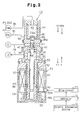
- the control valve CV includes a valve housing 41.
- a valve chamber 42, a communication passage 43, and a pressure sensing chamber 44 are defined in the valve housing 41.
- a transmission rod 45 extends through the valve chamber 42 and the communication passage 43.
- the transmission rod 45 moves in the axial direction, or in the vertical direction as viewed in the drawing.
- the rod 45 includes an upper block and a lower block coupled to each other by a thin portion. The thin portion is slidably fitted in the communication passage 43.
- the transmission rod 45 functions as a valve body.
- the communication passage 43 is disconnected from the pressure sensing chamber 44 by the upper block of the transmission rod 45.
- the valve chamber 42 is connected to the crank chamber 12 through a downstream section of the supply passage 28.
- the communication passage 43 is connected to the discharge chamber 22 through an upstream section of the supply passage 28.
- the valve chamber 42 and the communication passage 43 form a part of the supply passage 28.
- the upper end portion of the lower block of the transmission rod 45 functions as an opening adjuster 46, which is located in the valve chamber 42.
- a step defined between the valve chamber 42 and the communication passage 43 functions as a valve seat 47.
- the communication passage 43 functions as a valve hole.
- a pressure sensing member which is a bellows 48 in this embodiment, is located in the pressure sensing chamber 44.
- the upper end of the bellows 48 is fixed to the valve housing 41.
- a rod receiving recess 59 is formed in a movable lower end portion 48a of the bellows 48. Part of the upper block of the transmission rod 45 is loosely fitted in the rod receiving recess 59.
- the pressure sensing chamber 44 and the bellows 48 form a pressure sensing mechanism.
- the pressure sensing chamber 44 is divided into a first pressure chamber 49, which is the interior of the bellows 48, and a second pressure chamber 50, which is the exterior of the bellows 48.
- the first pressure chamber 49 is exposed to the pressure PdH at the first pressure monitoring point P1 through the first pressure introducing passage 35.
- the second pressure chamber 50 is exposed to the pressure PdL at the second pressure monitoring point P2 through the second pressure introducing passage 36.
- the movement of the lower end portion 48a of the bellows 48 toward the transmission rod 45 is limited by contact between the lower end portion 48a and the bottom of the second pressure chamber 50.
- the bottom of the second pressure chamber 50 functions as a pressure sensing member stopper.
- the elasticity of the bellows 48 urges the lower end portion 48a toward the bottom of the second pressure chamber 50.
- the force of the bellows 48 is a valve opening force based on its own elasticity and is referred to as f2.
- An electromagnetic actuator 51 is located below the valve housing 41.
- a cup shaped accommodation cylinder 52 is located in the radial center of the actuator 51.
- a cylindrical stator 53 is press fitted to the upper opening of the accommodation cylinder 52.
- the stator 53 is made of a magnetic material such as an iron-based material.
- the stator 53 defines a plunger chamber 54 in the lowest portion of the accommodation cylinder 52.
- An annular plate 55 made of a magnetic material is attached to the lower end of the actuator 51 from the lower opening.
- the plate 55 has a central hole and includes a cylindrical portion 55a, which protrudes upward from the periphery of the central hole.
- the plate 55 is attached to the actuator 51 by fitting the cylindrical portion 55a about the accommodation cylinder 52 and fills an annular space about the accommodation cylinder 52.
- An inverted cup-shaped plunger 56 is accommodated in the plunger chamber 54.
- the plunger 56 is made of a magnetic material and moves in the axial direction. Movement of the plunger 56 is guided by the inner surface 52a of the accommodation cylinder 52.
- An axial guide hole 57 is formed in the central portion of the stator 53. The lower portion of the transmission rod 45 is movably located in the guide hole 57.
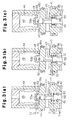
- the lower end of the transmission rod 45 is fixed to the plunger 56 in the plunger chamber 54 so that the plunger 56 and the transmission rod 45 move integrally. Upward movement of the transmission rod 45 and the plunger 56 is limited by contact between opening adjuster 46 of the transmission rod 45 and the valve seat 47. When the transmission rod 45 and the plunger 56 are at the uppermost position, opening adjuster 46 fully closes the communication passage 43 (see Fig. 3(c)).
- a spring seat 58 is fitted about the transmission rod 45 and is located in the valve chamber 42.
- a coil spring 60 extends between the spring seat 58 and part of the valve housing 41 that is adjacent to the valve seat 47.
- the coil spring 60 urges the opening adjuster 46 away from the valve seat 47.
- the spring constant of the coil spring 60 is significantly smaller than that of the bellows 48.
- the force f1 applied to the transmission rod 45 by the coil spring 60 is substantially constant regardless of the distance between opening adjuster 46 and the valve seat 47, or the compression state of the spring 60.
- the downward movement of the transmission rod 45 (the valve body) and the plunger 56 is limited by contact between the lower end surface of the plunger 56 and the bottom of the plunger chamber 54.
- the bottom of the plunger chamber 54 therefore functions as a valve body stopper.
- a coil 61 is wound about the accommodation cylinder 52 to surround the stator 53 and the plunger 56.
- the coil 61 is connected to a drive circuit 71, and the drive circuit 71 is connected to a controller (computer) 70.
- the controller 70 is connected to an external information detector 72.
- the controller 70 receives external information (on-off state of the air conditioner, the temperature of the passenger compartment, and a target temperature) from the detector 72. Based on the received information, the controller 70 commands the drive circuit 71 to supply electric current to the coil 61.
- the electric current from the drive circuit 71 generates magnetic flux in the coil 61.
- the flux flows to the plunger 56 through the plate 55 and the accommodation cylinder 52, and then flows from the plunger 56 to the coil 61 through the stator 53.
- an electromagnetic attraction force F the magnitude of which corresponds to the level of the electric current supplied to the coil 61, is generated between the plunger 56 and the stator 53.
- the force F is transmitted to the transmission rod 45 by the plunger 56.
- the electric current supplied to the coil 61 is controlled by adjusting the applied voltage. In this embodiment, the applied voltage is controlled by pulse-width modulation.
- the position of the transmission rod 45 (the valve body), or the opening degree of the control valve CV, is determined in the following manner.
- the downward force f1 of the coil spring 60 is dominant in determining the position of the transmission rod 45. Therefore, the transmission rod 45 is located at the lowest position by the force f1 of the coil spring 60, and opening adjuster 46 is separated from the valve seat 47 by the distance X1+X2, which fully opens the communication passage 43.
- the pressure in the crank chamber 12 is maximized under the given condition, which increases the difference between the crank chamber pressure and the pressure in the compression chambers 20 with the pistons 17 in between.
- the inclination angle of the swash plate 15 is minimized, and the displacement of the compressor is minimized.
- the transmission rod 45 When the transmission rod 45 is at the lowest position, the upper surface 45a of the transmission rod 45 is separated from the ceiling 59a of the rod receiving recess 59 by at least the distance X1.
- the force f2 of the bellows 48 acting on the lower end of the 48a becomes substantially eliminated.
- the transmission rod 45 is moved upward from the lowest position by at least the distance X1 and contacts the ceiling of the rod receiving recess 59. In other words, the transmission rod 45 is engaged with the bellows 48.
- the upward electromagnetic force F which is weakened by the downward force f1 of the spring 60, opposes the force based on the pressure difference ⁇ Pd, which is increased by the downward force f2 of the bellows 58.
- the position of opening adjuster 46 of the rod 45 relative to the valve seat 47 is determined such that the opposing forces are balanced.
- the effective opening degree of the control valve CV, controlled by the pressure difference ⁇ Pd, is determined between the middle opened position of Fig. 3(b) and the fully closed position of Fig. 3(c).
- the downward force based on the pressure difference ⁇ Pd decreases.
- the transmission rod 45 (the valve body) moves upward and decreases the opening degree of the communication passage 43. This lowers the pressure in the crank chamber 12. Accordingly, the inclination angle of the swash plate 15 is increased, and the compressor displacement is increased. As the compressor displacement is increased, the flow rate of refrigerant in the refrigerant circuit is increased, which increases the pressure difference ⁇ Pd.
- the target value of the pressure difference ⁇ Pd is determined by the duty ratio of current supplied to the coil 61.
- the control valve CV automatically determines the position of the transmission rod 45 (the valve body) according to changes of the pressure difference ⁇ Pd to maintain the target value of the pressure difference ⁇ Pd.
- the target value of the pressure difference ⁇ Pd is externally controlled by adjusting the duty ratio of current supplied to the coil 61.
- the electromagnetic actuator 51 of the control valve CV has the following characteristics.
- a recess 83 is formed in the lower end portion of the stator 53, which faces the plunger 56.
- the recess 83 includes an annular flat surface 81 and a peripheral wall 82.
- the flat surface 81 is perpendicular to the axis of the valve housing 41.
- the peripheral wall 82 has a tapered cross-section with an inclined inner surface 82a.
- a frustum portion 86 is formed in the upper end portion of the plunger 56, which faces the stator 53.
- An annular distal surface 84 which is perpendicular to the axis of the valve housing 41, is formed at the upper end of the frustum portion 86.
- an annular inclined surface 85 is formed at the periphery of the distal surface 84.
- the diameter of the flat surface 81 of the recess 83 and the diameter of the distal surface 84 of the frustum portion 86 are the same and that diameter is referred to as a diameter r.
- the taper angle of the peripheral wall 82 of the recess 83 and the taper angle of the inclined surface 85 of the frustum portion 86 are the same and are referred to as a taper angle ⁇ .
- the taper angle ⁇ is equal to or less than 20° (16° in this embodiment).
- the diameter r of the diameter of the distal surface 84 of the frustum portion 86 is equal to or is greater than 80% of the diameter R of the largest diameter portion 85b of the frustum portion 86. In other words, the ratio r/R is equal to or greater than 80% (84% in this embodiment).
- the coil 61 generates the maximum electromagnetic force Fmax when receiving an electric current having the maximum duty ratio.
- a greater value of the pressure difference ⁇ Pd (the refrigerant flow rate) can be obtained without increasing the size of the actuator 51.
- the characteristic line representing the electromagnetic force F (the minimum duty ratio) intersects the characteristic line representing the resultant f1+f2 of the spring forces at a midpoint between the fully closed position and the middle opened position.
- the electromagnetic force F of the comparison example is always greater than the resultant spring force f1+f2 in the range between the fully closed position and the middle open position. Therefore, if the coil 61 receives a current having a duty ratio that is equal to or greater than the minimum duty ratio when the pressure difference ⁇ Pd is zero, opening adjuster 46 is moved to the fully closed position. If the compressor displacement is gradually increased from the state in which the pressures in the refrigerant circuit are equalized ( ⁇ Pd ⁇ 0) by gradually increasing the duty ratio of the current supplied to the coil 61 from the minimum duty ratio, opening adjuster 46 is abruptly fully closes the communication passage 43. This abruptly and excessively increases the compressor displacement. As a result, the compressor torque acting on the engine E (the torque required for driving the compressor) is suddenly and excessively increased, which degrades the drivability of the vehicle.
- the preferable ranges of the taper angle ⁇ (0° ⁇ 20°) and the ratio of r and R (80% ⁇ r/R ⁇ 100%) are obtained in the following manner.
- Fig. 6(a) is a chart of experiment results showing whether the maximum electromagnetic force Fmax generated by the actuator 51 is equal to or greater than a predetermined level in various combinations of the taper angle ⁇ and the ratio r/R.
- the taper angle ⁇ increments by one degree from 14° to 25°
- the ratio r/R increments by two percent from 76% to 86%.
- Each sign ⁇ represents that the maximum electromagnetic force Fmax is equal to or more than the predetermined level in the corresponding combination.
- Each sign ⁇ represents that the maximum electromagnetic force Fmax cannot exceed the predetermined level at the corresponding combination.
- the electromagnetic force Fmax is increased.
- the ratio r/R is equal to or greater than 80%, all the combinations have the sign ⁇ .
- Figs. 6(b) is a chart of experiment results showing whether the rate of change of the electromagnetic force F in relation to the valve opening degree is equal to or less than a predetermined level when the coil 61 receives an electric current of the minimum duty ratio.
- the increments of the taper angle ⁇ and the ratio r/R ⁇ 100 are the same as those of Fig. 6(a).
- Each sign ⁇ represents that the rate of change of the electromagnetic force F is equal to or less than the predetermined level, or the force F changes gradually, at the corresponding combination.
- Each sign ⁇ represents that the rate of change of the electromagnetic force F exceeds the predetermined level.
- the rate of change of the electromagnetic force F is gradual when the taper angle ⁇ is small. Particularly, in the combinations in which the taper angle ⁇ is equal to or less than 20°, all the combinations have the sign ⁇ .
- a range that satisfies the preferable ranges of Figs. 6(a) and 6(b) is when the taper angle ⁇ is less than or equal to 20° and the ratio of r and R is greater than or equal to 80%, as shown in the final determination chart of Fig. 6(c).
- Fig. 7 shows a control valve CV according to the second embodiment.
- the control valve CV of the second embodiment is different from the control valve CV of the first embodiment in the position of the coil spring 60.
- the coil spring 60 is not located in the valve chamber 42 but in the plunger chamber 54.
- the spring 60 extends between the stator 53 and the plunger 56 to apply a force f1 to the plunger 56 in the valve opening direction, or in the direction opposing to the electromagnetic force F.
- the plunger 56 is cylindrical with its closed end located at the bottom.
- the spring 60 is located in the cylinder.
- the control valve CV of the second embodiment has the advantages (1) to (3) of the control valve CV of the first embodiment.
- the recess 83 may be formed in the plunger 56 and the frustum portion 86 may be formed in the stator 53. That is, the shapes of the plunger 56 and the stator 53 may be reversed from those of the illustrated embodiments.
- the first pressure monitoring point P1 may be located in the suction pressure zone, which includes the evaporator 33 and the suction chamber 21, and the second pressure monitoring point P2 may be located in the suction pressure zone at a position that is downstream of the first pressure monitoring point P1.
- the first pressure monitoring point P1 may be located in the discharge pressure zone, which includes the discharge chamber 22 and the condenser 31, and the second pressure monitoring point P2 may be located in the suction pressure zone, which includes the evaporator 33 and the suction chamber 21.
- the pressure monitoring points P1, P2 are located in the main circuit of the refrigerant circuit, i.e., the evaporator 33, the suction chamber 21, the cylinder bores 11a the discharge chamber 22, and the condenser 31. That is, the pressure monitoring points P1 and P2 are in a high pressure zone or a low pressure zone of the refrigerant circuit.
- the locations of the pressure monitoring points P1, P2 are not limited to those described in the illustrated embodiments.
- the pressure monitoring points P1, P2 may be located in the crank chamber 12, which is an intermediate pressure zone of a subcircuit for controlling the displacement, or a circuit including the supply passage 28, the crank chamber 12, and the bleed passage 27.
- the first pressure monitoring point P1 may be located in the discharge pressure zone, which includes the discharge chamber 22 and the condenser 31, and the second pressure monitoring point P2 may be located in the crank chamber 12.
- the interior of the bellows 48 may be used as the second pressure chamber 50 and the exterior of the bellows 48 may be used as the first pressure chamber 49.
- the first pressure monitoring point P1 is located in the crank chamber 12
- the second pressure monitoring point P2 is located in the suction pressure zone between the evaporator 33 and the suction chamber 21.
- the pressure sensing mechanism of the control valve CV may be actuated by the suction pressure or the discharge pressure.
- the first pressure monitoring point P1 may be used, and the second pressure chamber 50 may be vacuum or exposed to the atmospheric pressure.
- the present invention may be applied to an electromagnetic control valve that includes no pressure sensing mechanism.
- the present invention may be applied to a bleed control valve, which controls the pressure in the crank chamber 12 by controlling the opening degree of the bleed passage 27.
- the present invention may be applied to a control valve that adjusts the opening degrees of both of the bleed passage 27 and the supply passage 28 for controlling the pressure in the crank chamber 12.
- the bleed passage 27 and the supply passage 28 may be independent from each other like those in the illustrated embodiments.
- the bleed passage 27 and the supply passage 28 may have a common section between the control valve and the crank chamber 12. If the passages 27, 28 have the common section, the opening degree of the passages 27, 28 can be adjusted by a single valve body. In this case, a three-way control vale body is used.
- a control valve (CV) includes an accommodation cylinder (52), a coil (61), a stator (53), a plunger (56), and a valve body (45). Electromagnetic force is generated between the stator (53) and the plunger (56) and the plunger (56) moves relative to the stator (53).
- the valve body (45) adjusts the opening degree of a valve hole (43).
- a flat surface (81) and a peripheral wall (82) are formed in an end of the stator (53).
- the peripheral wall (82) has a tapered cross-section with an inclined inner surface (82a).
- the inclined inner surface (82a) and the flat surface (81) define a recess (83).
- the plunger (56) has a frustum portion (86).
- the frustum portion (86) includes a flat distal surface (84) and an annular inclined surface (85).
- the taper angle ( ⁇ ) of the peripheral wall (82) is equal to or less than twenty degrees.
- the diameter of the flat distal surface (84) of the frustum portion (86) is equal to or greater than eighty percent of the largest diameter of the annular inclined surface (85).
Landscapes
- Engineering & Computer Science (AREA)
- Mechanical Engineering (AREA)
- General Engineering & Computer Science (AREA)
- Compressors, Vaccum Pumps And Other Relevant Systems (AREA)
- Magnetically Actuated Valves (AREA)
- Control Of Positive-Displacement Pumps (AREA)
Abstract
Description
Claims (11)
- A control valve (CV) for changing the displacement of a compressor, comprising:an accommodation cylinder (52);a coil (61) located about the accommodation cylinder (52) ;a stator (53) located in the accommodation cylinder (52);a plunger (56) located in the accommodation cylinder (52), wherein, when electric current is supplied to the coil (61), electromagnetic force is generated between the stator (53) and the plunger (56) and the plunger (56) moves relative to the stator (53) in the accommodation cylinder (52), accordingly; anda valve body (45) coupled to the plunger (56), wherein, when the plunger (56) moves, the valve body (45) moves accordingly and adjusts the opening degree of a valve hole (43) ;
wherein a flat surface (81) and a peripheral wall (82) surrounding the flat surface (81) are formed in an end of one of the plunger (56) and the stator (53) that faces the other one of the plunger (56) and the stator (53), wherein the peripheral wall (82) has a tapered cross-section with an inclined inner surface (82a), and wherein the inclined inner surface (82a) and the flat surface (81) define a recess (83); and
wherein a frustum portion (86) is formed in an end of the other one of the plunger (56) and the stator (53) that faces the recess (83), wherein the frustum portion (86) includes a flat distal surface (84) and an annular inclined surface (85);the control valve (CV) being characterized in that the taper angle () of the peripheral wall (82) is equal to or less than twenty degrees, and wherein the diameter of the flat distal surface (84) of the frustum portion (86) is equal to or greater than eighty percent of the largest diameter of the annular inclined surface (85). - The control valve (CV) according to claim 1,
characterized in that the taper angle () of the peripheral wall (82) and the diameter of the flat distal surface (84) of the frustum portion (86) are determined based on the electromagnetic force generated by the coil (61) and the rate of change of the electromagnetic force in relation to the opening degree of the valve hole (43). - The control valve (CV) according to claim 2,
characterized in that the diameter of the flat surface (81) of the recess (83) is equal to the diameter of the distal surface (84) of the frustum portion (86), and wherein the taper angle () of the peripheral wall (82) of the recess (83) is equal to the angle defined by the annular inclined surface (85) of the frustum portion (86) and the inner wall of the accommodation cylinder (52). - The control valve (CV) according to claim 2 or 3,
characterized in that the compressor forms a part of a refrigerant circuit of an air conditioner and includes:wherein the valve hole (43) of the control valve (CV) is located in the supply passage (28), and wherein the valve body (45) adjusts the opening degree of the valve hole (43) to adjust the pressure in the control chamber (12).a control chamber (12), wherein the compressor displacement is changed by adjusting the pressure in the control chamber (12);a bleed passage (27) connecting the control chamber (12) to a suction pressure zone of the refrigerant circuit; anda supply passage (28) connecting a discharge pressure zone of the refrigerant circuit to the control chamber (12); - The control valve (CV) according to claim 4,
characterized by a valve chamber (42) for accommodating the valve body (45), wherein the valve chamber (42) is connected to the discharge pressure zone by an upstream section of the supply passage (28), and wherein a valve opening force based on pressure in the refrigerant circuit acts against the electromagnetic force. - The control valve (CV) according to claim 4 or 5,
characterized by a pressure sensing mechanism having a pressure sensing member (48), wherein the pressure sensing member (48) detects the pressure at a pressure monitoring point (P1, P2) located in the refrigerant circuit, wherein the pressure sensing member (48) is displaced based on changes in the pressure at the pressure monitoring point (P1, P2) to move the valve body (45) such that the displacement of the compressor is changed to cancel the pressure changes; and
wherein the electromagnetic force applied to the valve body (45) is changed in accordance with the level of electric current supplied to the coil (61) such that a target pressure, which is used as reference when the pressure sensing member (48) determines the position of the valve body (45), is changed. - The control valve (CV) according to claim 6,
characterized in that the pressure monitoring point is one of two pressure monitoring points (P1, P2) located along the refrigerant circuit, wherein the pressure sensing member (48) is displaced based on changes in the pressure difference between the pressure monitoring points (P1, P2), and wherein the target pressure is changed in accordance with the level of electric current supplied to the coil (61). - The control valve (CV) according to claim 7,
characterized in that the pressure monitoring points (P1, P2) are located in the discharge pressure zone of the refrigerant circuit. - The control valve (CV) according to any one of claims 6 to 8, characterized by:wherein the pressure sensing member (48) has an elasticity and is urged toward the pressure sensing member stopper by its own elasticity, wherein, when the valve body stopper limits the displacement of the valve body (45) and the pressure sensing member stopper limits the displacement of the pressure sensing member (48), a space exists between the valve body (45) and the pressure sensing member (48), and wherein the electromagnetic force acts against the forces of the spring (60) and the pressure sensing member (48).a valve body stopper for limiting the displacement of the valve body (45) ;a spring (60) for urging the valve body (45) toward the valve body (45) stopper, wherein the valve body (45) is movably engaged with the pressure sensing member (48); anda pressure sensing member stopper for limiting the displacement of the pressure sensing member (48);
- A compressor used in a refrigerant circuit of an air conditioner comprising:a control chamber (12), wherein the compressor displacement is changed by adjusting the pressure in the control chamber (12);a bleed passage (27) connecting the control chamber (12) to a suction pressure zone of the refrigerant circuit;a supply passage (28) connecting a discharge pressure zone of the refrigerant circuit to the control chamber (12); anda control valve (CV) for changing the displacement of a compressor, wherein the control valve (CV) includes:an accommodation cylinder (52);a coil (61) located about the accommodation cylinder (52);a stator (53) located in the accommodation cylinder (52);a plunger (56) located in the accommodation cylinder (52), wherein, when electric current is supplied to the coil (61), electromagnetic force is generated between the stator (53) and the plunger (56) and the plunger (56) moves relative to the stator (53) in the accommodation cylinder (52), accordingly; anda valve body (45) coupled to the plunger (56), wherein, when the plunger (56) moves, the valve body (45) moves accordingly and adjusts the opening degree of a valve hole (43);
wherein a flat surface (81) and a peripheral wall (82) surrounding the flat surface (81) are formed in an end of one of the plunger (56) and the stator (53) that faces the other one of the plunger (56) and the stator (53), wherein the peripheral wall (82) has a tapered cross-section with an inclined inner surface (82a), and wherein the inclined inner surface (82a) and the flat surface (81) define a recess (83); and
wherein a frustum portion (86) is formed in an end of the other one of the plunger (56) and the stator (53) that faces the recess (83), wherein the frustum portion (86) includes a flat distal surface (84) and an annular inclined surface (85);the compressor being characterized in that the taper angle () of the peripheral wall (82) is equal to or less than twenty degrees, and wherein the diameter of the flat distal surface (84) of the frustum portion (86) is equal to or greater than eighty percent of the largest diameter of the annular inclined surface (85). - The compressor according to claim 10, characterized in that the taper angle () of the peripheral wall (82) and the diameter of the flat distal surface (84) of the frustum portion (86) are determined based on the electromagnetic force generated by the coil (61) and the rate of change of the electromagnetic force in relation to the opening degree of the valve hole (43).
Applications Claiming Priority (2)
| Application Number | Priority Date | Filing Date | Title |
|---|---|---|---|
| JP2001140244 | 2001-05-10 | ||
| JP2001140244A JP2002332962A (en) | 2001-05-10 | 2001-05-10 | Control valve for variable displacement compressor |
Publications (3)
| Publication Number | Publication Date |
|---|---|
| EP1256718A2 true EP1256718A2 (en) | 2002-11-13 |
| EP1256718A3 EP1256718A3 (en) | 2004-01-21 |
| EP1256718B1 EP1256718B1 (en) | 2005-04-27 |
Family
ID=18986880
Family Applications (1)
| Application Number | Title | Priority Date | Filing Date |
|---|---|---|---|
| EP02010341A Expired - Lifetime EP1256718B1 (en) | 2001-05-10 | 2002-05-07 | Control valve for variable displacement compressor |
Country Status (7)
| Country | Link |
|---|---|
| US (1) | US6684654B2 (en) |
| EP (1) | EP1256718B1 (en) |
| JP (1) | JP2002332962A (en) |
| KR (1) | KR100448031B1 (en) |
| CN (1) | CN1385614A (en) |
| BR (1) | BR0201951B1 (en) |
| DE (1) | DE60203845T2 (en) |
Cited By (2)
| Publication number | Priority date | Publication date | Assignee | Title |
|---|---|---|---|---|
| WO2004059166A1 (en) * | 2002-12-24 | 2004-07-15 | Zexel Valeo Climate Control Corporation | Control valve for variable capacity compressor |
| CN100375842C (en) * | 2003-05-20 | 2008-03-19 | 乐金电子(天津)电器有限公司 | Piston initial position regulator for piston type compressor |
Families Citing this family (17)
| Publication number | Priority date | Publication date | Assignee | Title |
|---|---|---|---|---|
| JP4515053B2 (en) * | 2003-07-23 | 2010-07-28 | 株式会社トランストロン | Brake fluid pressure retention device |
| JP4316955B2 (en) * | 2003-08-11 | 2009-08-19 | イーグル工業株式会社 | Capacity control valve |
| JP2006112417A (en) * | 2004-09-16 | 2006-04-27 | Tgk Co Ltd | Control valve for variable displacement compressor |
| JP2006177300A (en) * | 2004-12-24 | 2006-07-06 | Toyota Industries Corp | Capacity control mechanism in variable displacement compressor |
| JP4309361B2 (en) * | 2005-03-14 | 2009-08-05 | パナソニック株式会社 | Electronic device control system and control signal transmitter |
| US7448653B2 (en) * | 2005-06-10 | 2008-11-11 | Value Plastics, Inc. | Female connector for releasable coupling with a male connector defining a fluid conduit |
| JP4612059B2 (en) * | 2006-02-07 | 2011-01-12 | 株式会社コガネイ | Proportional solenoid valve |
| JP2007263097A (en) * | 2006-03-30 | 2007-10-11 | Toyota Industries Corp | Flow detection device in variable displacement compressor |
| JP4714626B2 (en) * | 2006-04-13 | 2011-06-29 | 株式会社不二工機 | Control valve for variable displacement compressor |
| JP2007303416A (en) * | 2006-05-12 | 2007-11-22 | Toyota Industries Corp | Variable displacement compressor |
| JP4861956B2 (en) * | 2007-10-24 | 2012-01-25 | 株式会社豊田自動織機 | Capacity control valve in variable capacity compressor |
| JP5235569B2 (en) * | 2008-09-12 | 2013-07-10 | サンデン株式会社 | Capacity control valve, variable capacity compressor and capacity control system of variable capacity compressor |
| JP5391648B2 (en) * | 2008-10-28 | 2014-01-15 | 株式会社豊田自動織機 | Capacity control mechanism in variable capacity compressor |
| CN103016327B (en) * | 2011-09-28 | 2016-03-16 | 上海三电贝洱汽车空调有限公司 | Electrically-controlled valve |
| CN102937084A (en) * | 2012-10-30 | 2013-02-20 | 合肥通用机械研究院 | Air volume regulating system for compressor |
| CN104089072A (en) * | 2014-06-17 | 2014-10-08 | 贵州新安航空机械有限责任公司 | Electromagnetic valve core structure with enhanced electromagnetic force |
| JP6141930B2 (en) * | 2015-09-16 | 2017-06-07 | 株式会社豊田自動織機 | Capacity control valve |
Family Cites Families (7)
| Publication number | Priority date | Publication date | Assignee | Title |
|---|---|---|---|---|
| JP2551416B2 (en) * | 1986-10-07 | 1996-11-06 | 株式会社ゼクセル | Automotive air conditioner |
| DE69501863T2 (en) * | 1994-09-09 | 1998-07-23 | Gen Motors Corp | Actuator for an exhaust gas recirculation valve |
| JP4149558B2 (en) * | 1998-03-27 | 2008-09-10 | サンデン株式会社 | Volume control valve for variable capacity compressor |
| JP3911937B2 (en) | 1999-08-04 | 2007-05-09 | 株式会社豊田自動織機 | Control method for air conditioner and variable capacity compressor |
| JP2001133053A (en) * | 1999-11-01 | 2001-05-18 | Toyota Autom Loom Works Ltd | Air conditioner |
| JP2001221158A (en) | 1999-11-30 | 2001-08-17 | Toyota Autom Loom Works Ltd | Control valve for variable displacement compressor |
| US6439213B2 (en) * | 2000-02-24 | 2002-08-27 | Delphi Technologies, Inc. | Shaft leakage arresting system for a gas management valve |
-
2001
- 2001-05-10 JP JP2001140244A patent/JP2002332962A/en active Pending
-
2002
- 2002-03-06 KR KR10-2002-0011967A patent/KR100448031B1/en not_active Expired - Fee Related
- 2002-05-07 EP EP02010341A patent/EP1256718B1/en not_active Expired - Lifetime
- 2002-05-07 DE DE60203845T patent/DE60203845T2/en not_active Expired - Lifetime
- 2002-05-08 BR BRPI0201951-5A patent/BR0201951B1/en not_active IP Right Cessation
- 2002-05-09 CN CN02119337A patent/CN1385614A/en active Pending
- 2002-05-09 US US10/143,357 patent/US6684654B2/en not_active Expired - Fee Related
Cited By (2)
| Publication number | Priority date | Publication date | Assignee | Title |
|---|---|---|---|---|
| WO2004059166A1 (en) * | 2002-12-24 | 2004-07-15 | Zexel Valeo Climate Control Corporation | Control valve for variable capacity compressor |
| CN100375842C (en) * | 2003-05-20 | 2008-03-19 | 乐金电子(天津)电器有限公司 | Piston initial position regulator for piston type compressor |
Also Published As
| Publication number | Publication date |
|---|---|
| BR0201951A (en) | 2003-04-22 |
| KR100448031B1 (en) | 2004-09-08 |
| EP1256718A3 (en) | 2004-01-21 |
| DE60203845T2 (en) | 2006-01-26 |
| US20030014990A1 (en) | 2003-01-23 |
| KR20020086220A (en) | 2002-11-18 |
| BR0201951B1 (en) | 2010-09-21 |
| US6684654B2 (en) | 2004-02-03 |
| DE60203845D1 (en) | 2005-06-02 |
| EP1256718B1 (en) | 2005-04-27 |
| JP2002332962A (en) | 2002-11-22 |
| CN1385614A (en) | 2002-12-18 |
Similar Documents
| Publication | Publication Date | Title |
|---|---|---|
| EP1256718B1 (en) | Control valve for variable displacement compressor | |
| US5890876A (en) | Control valve in variable displacement compressor | |
| US6257836B1 (en) | Displacement control valve for variable displacement compressor | |
| US20150104334A1 (en) | Variable displacement swash plate compressor | |
| US6200105B1 (en) | Control valve in variable displacement compressor and method of manufacture | |
| US6682314B2 (en) | Control valve for variable displacement type compressor | |
| EP1039129A2 (en) | Device and method for controlling displacement of variable displacement compressor | |
| US5975859A (en) | Control valve in variable displacement compressor and its assembling method | |
| EP1083335A2 (en) | Control valve for variable displacement compressor | |
| US20110091334A1 (en) | Variable Displacement Compressor | |
| US6927656B2 (en) | Electromagnetic actuator and method for manufacturing electromagnetic actuator, and control valve for variable displacement compressor using electromagnetic actuator | |
| US6443707B1 (en) | Control valve for variable displacement compressor | |
| US6672844B2 (en) | Apparatus and method for controlling variable displacement compressor | |
| US6637228B2 (en) | Control valve of variable displacement compressor | |
| US6702251B2 (en) | Control valve in variable displacement compressor and method of manufacturing the same | |
| US6783332B2 (en) | Control valve of variable displacement compressor with pressure sensing member | |
| US6578372B2 (en) | Apparatus and method for controlling variable displacement compressor | |
| EP1001171A2 (en) | Variable displacement compressor | |
| EP1033489A2 (en) | Displacement control valve for variable displacement type compressors | |
| EP1186776A2 (en) | Control valve for variable displacement compressor | |
| EP1223342B1 (en) | Variable displacement compressor with a control valve. | |
| US20060083625A1 (en) | Control valve for variable displacement compressor | |
| EP1081379A1 (en) | Control valve for variable displacement compressor | |
| US20020152763A1 (en) | Control device of variable displacement compressor |
Legal Events
| Date | Code | Title | Description |
|---|---|---|---|
| PUAI | Public reference made under article 153(3) epc to a published international application that has entered the european phase |
Free format text: ORIGINAL CODE: 0009012 |
|
| 17P | Request for examination filed |
Effective date: 20020507 |
|
| AK | Designated contracting states |
Kind code of ref document: A2 Designated state(s): AT BE CH CY DE DK ES FI FR GB GR IE IT LI LU MC NL PT SE TR |
|
| AX | Request for extension of the european patent |
Free format text: AL;LT;LV;MK;RO;SI |
|
| PUAL | Search report despatched |
Free format text: ORIGINAL CODE: 0009013 |
|
| AK | Designated contracting states |
Kind code of ref document: A3 Designated state(s): AT BE CH CY DE DK ES FI FR GB GR IE IT LI LU MC NL PT SE TR |
|
| AX | Request for extension of the european patent |
Extension state: AL LT LV MK RO SI |
|
| 17Q | First examination report despatched |
Effective date: 20040618 |
|
| GRAP | Despatch of communication of intention to grant a patent |
Free format text: ORIGINAL CODE: EPIDOSNIGR1 |
|
| AKX | Designation fees paid |
Designated state(s): DE FR IT SE |
|
| GRAS | Grant fee paid |
Free format text: ORIGINAL CODE: EPIDOSNIGR3 |
|
| GRAA | (expected) grant |
Free format text: ORIGINAL CODE: 0009210 |
|
| AK | Designated contracting states |
Kind code of ref document: B1 Designated state(s): DE FR IT SE |
|
| REG | Reference to a national code |
Ref country code: SE Ref legal event code: TRGR |
|
| REG | Reference to a national code |
Ref country code: IE Ref legal event code: FG4D |
|
| REF | Corresponds to: |
Ref document number: 60203845 Country of ref document: DE Date of ref document: 20050602 Kind code of ref document: P |
|
| PLBE | No opposition filed within time limit |
Free format text: ORIGINAL CODE: 0009261 |
|
| STAA | Information on the status of an ep patent application or granted ep patent |
Free format text: STATUS: NO OPPOSITION FILED WITHIN TIME LIMIT |
|
| ET | Fr: translation filed | ||
| 26N | No opposition filed |
Effective date: 20060130 |
|
| PGFP | Annual fee paid to national office [announced via postgrant information from national office to epo] |
Ref country code: SE Payment date: 20130513 Year of fee payment: 12 |
|
| PGFP | Annual fee paid to national office [announced via postgrant information from national office to epo] |
Ref country code: FR Payment date: 20130531 Year of fee payment: 12 Ref country code: IT Payment date: 20130515 Year of fee payment: 12 |
|
| PG25 | Lapsed in a contracting state [announced via postgrant information from national office to epo] |
Ref country code: SE Free format text: LAPSE BECAUSE OF NON-PAYMENT OF DUE FEES Effective date: 20140508 |
|
| REG | Reference to a national code |
Ref country code: SE Ref legal event code: EUG |
|
| REG | Reference to a national code |
Ref country code: FR Ref legal event code: ST Effective date: 20150130 |
|
| PG25 | Lapsed in a contracting state [announced via postgrant information from national office to epo] |
Ref country code: IT Free format text: LAPSE BECAUSE OF NON-PAYMENT OF DUE FEES Effective date: 20140507 |
|
| PG25 | Lapsed in a contracting state [announced via postgrant information from national office to epo] |
Ref country code: FR Free format text: LAPSE BECAUSE OF NON-PAYMENT OF DUE FEES Effective date: 20140602 |
|
| PGFP | Annual fee paid to national office [announced via postgrant information from national office to epo] |
Ref country code: DE Payment date: 20150428 Year of fee payment: 14 |
|
| REG | Reference to a national code |
Ref country code: DE Ref legal event code: R119 Ref document number: 60203845 Country of ref document: DE |
|
| PG25 | Lapsed in a contracting state [announced via postgrant information from national office to epo] |
Ref country code: DE Free format text: LAPSE BECAUSE OF NON-PAYMENT OF DUE FEES Effective date: 20161201 |