EP1256518A2 - Stern tube shaft sealing apparatus - Google Patents
Stern tube shaft sealing apparatus Download PDFInfo
- Publication number
- EP1256518A2 EP1256518A2 EP02009400A EP02009400A EP1256518A2 EP 1256518 A2 EP1256518 A2 EP 1256518A2 EP 02009400 A EP02009400 A EP 02009400A EP 02009400 A EP02009400 A EP 02009400A EP 1256518 A2 EP1256518 A2 EP 1256518A2
- Authority
- EP
- European Patent Office
- Prior art keywords
- seal
- stern
- oil
- water
- chamber
- Prior art date
- Legal status (The legal status is an assumption and is not a legal conclusion. Google has not performed a legal analysis and makes no representation as to the accuracy of the status listed.)
- Withdrawn
Links
- 238000007789 sealing Methods 0.000 title claims abstract description 17
- XLYOFNOQVPJJNP-UHFFFAOYSA-N water Substances O XLYOFNOQVPJJNP-UHFFFAOYSA-N 0.000 claims abstract description 79
- 239000012530 fluid Substances 0.000 claims abstract description 13
- 239000013535 sea water Substances 0.000 description 14
- 239000013013 elastic material Substances 0.000 description 6
- 208000035874 Excoriation Diseases 0.000 description 4
- 238000005299 abrasion Methods 0.000 description 4
- 238000012856 packing Methods 0.000 description 4
- 239000000839 emulsion Substances 0.000 description 3
- 238000005461 lubrication Methods 0.000 description 3
- 238000005086 pumping Methods 0.000 description 3
- 238000011144 upstream manufacturing Methods 0.000 description 3
- 230000015556 catabolic process Effects 0.000 description 1
- 238000006731 degradation reaction Methods 0.000 description 1
- 230000020169 heat generation Effects 0.000 description 1
Images
Classifications
-
- B—PERFORMING OPERATIONS; TRANSPORTING
- B63—SHIPS OR OTHER WATERBORNE VESSELS; RELATED EQUIPMENT
- B63B—SHIPS OR OTHER WATERBORNE VESSELS; EQUIPMENT FOR SHIPPING
- B63B59/00—Hull protection specially adapted for vessels; Cleaning devices specially adapted for vessels
-
- B—PERFORMING OPERATIONS; TRANSPORTING
- B63—SHIPS OR OTHER WATERBORNE VESSELS; RELATED EQUIPMENT
- B63H—MARINE PROPULSION OR STEERING
- B63H23/00—Transmitting power from propulsion power plant to propulsive elements
- B63H23/32—Other parts
- B63H23/321—Bearings or seals specially adapted for propeller shafts
Definitions
- This invention relates to a stern tube shaft sealing device, which is called apparatus, wherein the apparatus is attached on a stern tube between a stern side and a stem side for sealing between seawater and bearing oil at an outer circumference of a propeller shaft.
- Fig. 2 is a semi sectional view showing an apparatus for sealing a shaft of a stern tube according to the related art, by cutting with a plane passing through a shaft center.
- numeral 101 designates a propeller shaft.
- the propeller shaft 101 penetrates a stern tube bearing, which is not shown in the figure and is provided on a shaft hole under a stern of a hull 100.
- the propeller shaft 101 protrudes to a stern side.
- Numeral 102 designates a propeller boss, which is fixed to an outer end of the propeller shaft 101.
- a sleeve 103 is externally fitted via a packing 104.
- the sleeve 103 is attached to the propeller shaft 101.
- An outer circumference of the propeller shaft 101 is surrounded by a plurality of casing segments 105 ⁇ 108.
- the casing segments 105 ⁇ 108 are connected to be watertight in an axial direction.
- the casing segment 108 which locates nearest to a stem, is connected to an end of the shaft hole under the stern of the hull 100.
- the casing segment 105 locates nearest to the stern.
- the casing segment 106 is connected at a stem side thereof.
- water seals 109, 110 are arranged with an elastic material, such as rubber.
- the water seals 109, 110 have bosses 109a, 110a, and brims 109b, 110b, respectively.
- the bosses 109a, 110a are set to the outer circumference of the sleeve 103 in a fitted and sealed condition.
- Each end of the brims 109b, 110b which directs to the stem side, opposes to inward flanges 106a, 107a of the casing segments 106, 107 in the axial direction.
- the casing segment 107 slides on the water seal 110 at the stem side.
- the casing segment 108 locates next thereto.
- An oil seal 111 is installed between both insides of the casing segment 107 and the casing segment 108 that locates nearest to the stem.
- the oil seal 111 is made of an elastic material, such as rubber.
- the oil seal 111 extends to the stem side and has a seal lip 111a.
- the seal lip 111a is in contact with the outer circumference of the sleeve 103 in a sealed state.
- a space 112 locates at the bearing side, and fronts the oil seal 111. In the space 112, bearing oil O having a certain pressure is filled for supply to the stern tube bearing.
- An annular seal chamber 113 is bounded by the water seal 109 at the stern side and the water seal 110 at the stem side.
- a line 114 for supplying clean water opens.
- the line 114 penetrates and extends from an inboard clean water supplier, which is not shown in the figure, through the casing segments 108, 107, and 106.
- An annular drain chamber 115 is bounded by the water seal 110 at the stem side and the oil seal 111. Further, at the annular drain chamber 115, a line 116 for collecting fluid opens.
- the line 116 penetrates and extends from an inboard collector, which is not shown in the figure, through the casing segments 108 and 107.
- clean water a pressure of which is slightly higher than that of seawater at a draft depth
- clean water is supplied from a supply source of clean water via the line 114 to the seal chamber 113.
- Most of this is gradually discharged into outboard seawater W, which pushes the brim 109b of the water seal 109 at the stern side open from the inner flange 106a of the casing segment 106.
- it can completely avoid entering of seawater W into the seal chamber 113.
- leaked clean water or leaked bearing oil is collected to the inboard collector via the line 116.
- leaked clean water is the one leaked from a slide part between the brim 110b of the water seal 110 at the stem side and the inward flange 107a of the casing segment 107 to the drain chamber 115.
- Leaked bearing oil is the one leaked from a slide part between the seal lip 111a of the oil seal 111 and the sleeve 103 to the drain chamber 115.
- spiral grooves are usually formed at the slide end of the seal lip 111a of the oil seal 111.
- the spiral grooves show a pumping function on the outer circumferential surface of the sleeve 103.
- This pumping function is to return bearing oil O back to the space 112 at the bearing side, in order not to enter the drain chamber 115. Therefore, if clean water remains in the drain chamber 115, such remaining water is sent to the space 112 at the bearing side by the pumping function at the slide end of the seal lip 111a. Therefore, it is pointed out that clean water mixes with bearing oil O in the space 112 at the bearing side, which leads emulsion of bearing oil O to cause poor lubrication at the stern tube bearing.
- a differential pressure between the pressure in the drain chamber 115 and the higher pressure of the bearing oil O in the space 112 at the bearing side acts in a direction such that the seal lip 111a of the oil seal 111 contacts with the outer circumferential surface of the sleeve 103 in a sealed state.
- a differential pressure relative to the pressure of the bearing oil O in the space 112 at the bearing side in other words, a surface pressure of the seal lip 111a relative to the sleeve 103, becomes large. Therefore, load of the slide end of the seal lip 111a increases. It is further pointed out that it probably causes early abrasion or degradation by heat, which brings poor sealing function.
- the object of the invention is to provide a shaft sealing constitution such that it can certainly avoid entering of the fluid leaked from the side of the water seal to the side of the bearing.
- Another object of the invention is to reduce the sliding load of the seal and to raise its durability.
- an apparatus comprises a case arranged so as to surround an outer circumference of a propeller shaft of the stern tube; a water seal, an oil seal, and an intermediate seal provided between the water seal and the oil seal at an inner circumference of the case; characterized in that the oil seal and the intermediate seal are made of rubber elastic bodies and provided with bases held by the case and seal lips slidably contacting at a side of the propeller shaft, the seal lip of the oil seal facing to an inside of a hull, and the seal lip of the intermediate seal facing to a side of the stern, wherein an air chamber is bounded between the oil seal and the intermediate seal, and wherein an air supplier for supplying fluid having a higher pressure than in a drain chamber is connected to the air chamber.
- air having a pressure not less than the pressure that is equal to the tension pressure of the seal lip of the intermediate seal is supplied to the air chamber that is bounded between the oil seal and the intermediate seal.
- air pushes the seal lip of the intermediate seal open and flows out into the drain chamber.
- An air jet formed thereby certainly seals remaining water in the drain chamber to the air chamber. Therefore, it can certainly avoid mixing of remaining water in the drain chamber with bearing oil in the space at the bearing side through the air chamber.
- the seal lip of the intermediate seal is set to be a non-contact condition with the side of the propeller shaft. Therefore, it can substantially avoid generation of abrasion or sliding heat. Sliding load of the seal lip of the oil seal can be reduced, which results in extension of lifetime for durability.
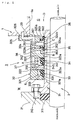
- Fig. 1 is a semi sectional view showing an apparatus (a stern tube shaft sealing apparatus) according to a preferred embodiment of the invention, by cutting with a plane passing through a shaft center.
- reference numeral 1 designates one part under a stern of a hull.
- Numeral 2 designates a propeller shaft, which protrudes from a shaft hole opening 1a of the hull 1 to a stern side of the hull 1.
- Numeral 21 designates a propeller boss, which is fixed on an end at the stern side of the propeller shaft 2.
- the propeller shaft 2 protrudes from the shaft hole opening 1a of the hull 1 to the stern side.
- a stern tube shaft sealing device (an apparatus) 3 is provided at an outer circumferential side of the propeller shaft 2.
- the device 3 has a sleeve 31, a casing 32, water seals 33, 34, an intermediate seal 35, and an oil seal 36.
- the sleeve 31 is externally fitted so as to be watertight via a packing 311 to a protrusion of the propeller shaft 2 from the hull 1.
- the sleeve 31 is fixed to the propeller boss 21 by bolts 312.
- the casing 32 is so arranged as to surround the outer circumference thereof, and is connected to the hull 1.
- the water seals 33, 34, the intermediate seal 35, and the oil seal 36 are arranged between the casing 32 and the sleeve 31.
- the device 3 avoids leakage of bearing oil O into outboard seawater W via a circumference of the shaft, and avoids entering of outboard seawater W into inboard via the circumference of the shaft.
- bearing oil O is supplied to a stern tube bearing (not shown in the figure), which locates at a right hand side in Fig. 1 and supports the propeller shaft 2.
- the casing 32 has a plurality of casing segments 321 ⁇ 325, which are connected in an axial direction.
- the casing segment 325 which locates nearest to a stem, is connected to be watertight to the hull 1.
- a gasket 326 seals between the casing segment 325 and the hull 1.
- the casing segment 321 locates nearest to the stern and at the stern side.
- the casing segment 322 locates secondly from the stern.
- inward flanges 321a, 322a are respectively formed. Inner circumferences of the inward flanges 321a, 322a are close to an outer circumferential surface of the sleeve 31.
- the water seal 33 at the stern side is arranged at the inner circumference of the casing segment 321 and between the inward flanges 321a, 322a.
- the water seal 33 is formed of an elastic material, such as rubber.
- the casing segment 321 locates nearest to the stern.
- the water seal 33 has a boss 331 and a brim 332.
- the boss 331 is so set as to fit and seal by a tightening force of an annular garter spring 333.
- the brim 332 has an end face, which faces to the stem side and contacts to seal the inward flange 322a of the casing segment 322.
- the casing segment 323 locates thirdly from the stern. At the stern side and inner circumference of the casing segment 323, an inward flange 323a is formed. An inside of the inward flange 323a is close to the outer circumference of the sleeve 31.
- the water seal 34 at the stem side is arranged between the inward flange 322a of the casing segment 322 and the inward flange 323a of the third casing segment 323.
- the water seal 34 at the stem side locates at the inner circumferential space of the second casing segment 322 from the stern side.
- the water seal 34 at the stem side has the same structure as the water seal 33 at the stern side.
- the boss 341 comprises a boss 341 and a brim 342 and has an elastic material such as rubber.
- the boss 341 is so set as to fit and seal the outer circumferential surface of the sleeve 31 by a tightening force of an annular garter spring 343.
- the brim 342 has an end face, which directs to the stem side and opposes another end face facing to the stern side of the inward flange 323a of the casing segment 323.
- the water seals 33, 34 rotate together with the propeller shaft 2, which shows a shaft sealing function between the brims 332, 342 and the inward flanges 322a, 323a of the casing segments 322, 323 at the non-rotating casing 32.
- the casing segment 323 locates thirdly from the stern. At the stem side and inner circumference of the casing segment 323, a seal support 323b is formed. The casing segment 324 locates fourthly from the stern. At the stern side and inner circumference of the third casing segment 324, a seal support 324a is formed. The seal support 324a extends in between the seal support 323b and the sleeve 31.
- the intermediate seal 35 has a base 351 and a seal lip 352.
- the intermediate seal 35 is formed of an elastic material such as rubber.
- the base 351 is so fixed as to seal and contact between the seal supports 323b, 324a.
- the seal lip 352 extends from the inner circumference of the base 351 to the stern side.
- the seal lip 352 has an end that is given a tightening force by a garter spring 353 and contacts and seals the outer circumferential surface of the sleeve 31.
- the casing segment 324 locates fourthly from the stern.
- a seal support 324b is formed at the stem side and inner circumference of the casing segment 324.
- the seal support 324b locates symmetrically to the seal support 324a in the axial direction.
- a seal support 325a is formed at the inner circumference of the casing segment 325.
- the casing segment 325 locates nearest to the stem.
- the seal support 324b extends in between the seal support 325a and the sleeve 31.
- the oil seal 36 has a base 361 and a seal lip 362.
- the oil seal 36 is formed of an elastic material such as rubber. The base 361 is so fixed as to seal and contact between the seal supports 324b, 325a.
- the seal lip 362 extends from the inner circumference of the base 361 to the stem side.
- the seal lip 362 has an end, which is given a tightening force by a garter spring 363 and contacts and seals the outer circumference of the sleeve 31.
- the intermediate seal 35 and the oil seal 36 do not rotate, and show a shaft sealing function between each end of the seal lips 352, 362 and the outer circumferential surface of the sleeve 31.
- the sleeve 31 rotates integrally with the propeller shaft 2.
- the base 351 of the intermediate seal 35 is constituted as a means of a packing for sealing between the casing segments 323, 324.
- the base 361 of the oil seal 36 is constituted as a means of a packing for sealing between the casing segments 324, 325.
- An inner circumferential space of the second casing segment 322 from the stern is constituted of an annular seal chamber A, which is bounded by the water seals 33, 34.
- a line 37 for supplying clean water which is constituted of a pipeline, opens at the seal chamber A.
- the line 37 penetrates and extends from the casing segment 322 through the casing segments 323 ⁇ 325 and the hull 1.
- An upstream end of the line 37 is connected to a clean water supplier, which is arranged inboard and constituted of a constant flow valve and a strainer and so on that are not shown in the figure.
- a pressure of clean water supplied to the seal chamber A is set higher than the pressure that is equal to the pressure of seawater at a draft depth, which acts on the water seal 33 at the stern side.
- An inner circumferential space of the third casing segment 323 from the stern side is constituted of an annular drain chamber B, which is bounded by the water seal 34 and the intermediate seal 35.
- a line 38 for collecting fluid which is constituted of a pipeline, opens at the drain chamber B.
- the line 38 penetrates and extends from the casing segment 323 of the casing 32 through the casing segments 324, 325 and the hull 1.
- An upstream end of the line 38 is connected to a collector, which is arranged inboard and constituted of a pump, a collecting tank and so on that are not shown in the figure.
- An inner circumferential space of the fourth casing segment 324 from the stern is constituted of an annular air chamber C, which is bounded by the intermediate seal 35 and the oil seal 36.
- a line 39 for supplying air which is constituted of a pipeline, opens at the air chamber C.
- the line 39 penetrates and extends from the casing segment 324 of the casing 32 through the casing segment 325 and the hull 1.
- An upstream end of the line 39 is connected to an air supplier, which is arranged inboard and constituted of a regulator, flow meter, filter, and so on that are not shown in the figure.
- the amount of air supplied into the air chamber C is not limited, about 40 ⁇ 50 NL/min is enough for it.
- bearing oil O is filled at the inner circumferential space of the shaft hole opening 1a of the hull 1, namely a space D at the bearing side in front of the oil seal 36.
- Bearing oil O is supplied to the stern tube bearing at the right hand side in Fig. 1.
- the water seal 33 at the stern side is arranged at an inner circumferential space E of the casing segment 321 that locates nearest to the stern.
- seawater W is filled through a space between the inward flange 321a of the casing segment 321 and the outer circumferential surface of the sleeve 31.
- clean water is continuously supplied from the clean water supplier to the seal chamber A via the line 37.
- the pressure of clean water is slightly higher than that of seawater at the draft depth.
- the pressure of clean water which is supplied to the seal chamber A, acts on the brim 342 of the water seal 34 at the stem side in such a direction as to push it to the inward flange 323a of the third casing segment 323 from the stern side. While on the brim 332 of the water seal 33 at the stern side, such pressure acts in such a direction as to push it open from the inward flange 322a of the second casing segment 322 from the stern side.
- the pressure of clean water in the seal chamber A is higher than that of seawater W that acts on the brim 332 of the water seal 33 at the stern side as a back pressure.
- clean water is gradually discharged into outboard seawater W, as pushing the brim 332 of the water seal 33 open at the stern side against the pressure of seawater.
- the amount is almost the same as the amount supplied into the seal chamber A from the line 37. Therefore, in a space between the brim 332 of the water seal 33 and the inward flange 322a of the casing segment 322, a jet of clean water to the side of seawater W is formed. Hereby it certainly avoids entering of seawater W into the seal chamber A.
- a microscopic opening is formed at the sealed slide part between the water seal 34 at the stem side and the inward flange 323a of the casing segment 323.
- Clean water which leaks from the seal chamber A to the drain chamber B via the microscopic opening, is sealed by the intermediate seal 35 at the stem side. That is, the seal lip 352 of the intermediate seal 35 seals and contacts with the outer circumferential surface of the sleeve 31 by its own tension pressure and a tension pressure of the garter spring 353, and seals clean water in the drain chamber B. Because clean water sealed therein is collected to the inboard collector via the line 38, it avoids entering to the side of the air chamber C.
- the air chamber C air is continuously supplied from the air supplier via the line 39. Thereby a certain air pressure is formed. Then, the air pressure acts on the inner circumferential surface of the seal lip 352 of the intermediate seal 35 and the inner circumferential surface of the seal lip 362 of the oil seal 36, in such a direction that it acts against the tension pressure of the seal lips 352, 362, namely the outward direction.
- the seal lip 352 of the intermediate seal 35 directs to the stern side.
- the seal lip 362 of the oil seal 36 directs to the stem side.
- the pressure value of the outward direction which is equal to the tension pressure of the seal lip 352 of the intermediate seal 35, was confirmed to be 0.005 ⁇ 0.01MPa as a result of experiments.
- the pressure of bearing oil O in the space D at the bearing side acts in the same direction as the tension pressure of the seal lip 362.
- the pressure of bearing oil O is set about 0.03MPa higher than the atmospheric pressure, for example.
- the air pressure, which is stored in the air chamber C is equal to or higher than the drain chamber B (which is equal to or less than atmospheric pressure) by 0.005 ⁇ 0.01MPa, in other words, equal to or higher than the pressure that is equal to the tension pressure of the seal lip 352 of the intermediate seal 35, the seal lip 352 is pushed slightly open from the outer circumferential surface of the sleeve 31. Then, the air in the air chamber C flows out into the drain chamber B by the same amount of the flow (about 40 ⁇ 50 NL/min) supplied from the line 39.
- the pressure of bearing oil O which is higher than the air pressure in the air chamber C, acts on the oil seal 36 in such a direction as to seal and contact the seal lip 362 with the sleeve 31 as described above. Therefore, air in the air chamber C will not flow out into the space D at the bearing side by pushing the seal lip 362 open.
- the seal lip 362 of the oil seal 36 has an elasticity of itself and receives a tightening force of the garter spring 363 and a force of reducing diameter by the pressure of bearing oil O.
- the tension pressure by the elasticity of the garter spring 363 and the seal lip 362 itself is balanced with and cancelled by the air pressure in the air chamber C. Therefore, the tension pressure of the seal lip 362 of the oil seal 36 is substantially given by only the pressure of bearing oil O (about 0.03MPa). Therefore, sliding load of the seal lip 362 is reduced, which effectively leads to reduction of abrasion or sliding heat generation.
- a stern tube shaft sealing apparatus is such an apparatus that a fluid collecting means is provided to be connected to the drain chamber B bounded between the water seal 34 and the intermediate seal 35.
- the seal lip of the oil seal is directed to the stem side.
- the seal lip of the intermediate seal directs to the stern side.
- a line for collecting the fluid is provided in a space for leakage between the water seal and the intermediate seal. Therefore, water leaked from the water seal to the drain chamber is sealed by the intermediate seal and is collected by the line for collecting fluid. Thus, entering to the side of the oil seal is avoided. Therefore, it can be avoided that water leaked in the drain chamber mixes through the oil seal to the bearing oil, which causes emulsion of bearing oil or lack of lubrication at the stern tube bearing.
Landscapes
- Chemical & Material Sciences (AREA)
- Engineering & Computer Science (AREA)
- Combustion & Propulsion (AREA)
- Mechanical Engineering (AREA)
- Ocean & Marine Engineering (AREA)
- Sealing With Elastic Sealing Lips (AREA)
- Sealing Of Bearings (AREA)
- Sealing Using Fluids, Sealing Without Contact, And Removal Of Oil (AREA)
Abstract
Description
- This invention relates to a stern tube shaft sealing device, which is called apparatus, wherein the apparatus is attached on a stern tube between a stern side and a stem side for sealing between seawater and bearing oil at an outer circumference of a propeller shaft.
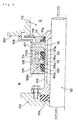
- Fig. 2 is a semi sectional view showing an apparatus for sealing a shaft of a stern tube according to the related art, by cutting with a plane passing through a shaft center. In Fig. 2,
numeral 101 designates a propeller shaft. Thepropeller shaft 101 penetrates a stern tube bearing, which is not shown in the figure and is provided on a shaft hole under a stern of ahull 100. Thepropeller shaft 101 protrudes to a stern side. Numeral 102 designates a propeller boss, which is fixed to an outer end of thepropeller shaft 101. At an outer circumference of a protruding part of thepropeller shaft 101, which protrudes from thehull 100 to the stern side, asleeve 103 is externally fitted via apacking 104. Thesleeve 103 is attached to thepropeller shaft 101. An outer circumference of thepropeller shaft 101 is surrounded by a plurality ofcasing segments 105∼108. Thecasing segments 105∼108 are connected to be watertight in an axial direction. Thecasing segment 108, which locates nearest to a stem, is connected to an end of the shaft hole under the stern of thehull 100. - The
casing segment 105 locates nearest to the stern. Thecasing segment 106 is connected at a stem side thereof. At the inner circumference of thecasing segment 105 and the inner circumference of thecasing segment 106,water seals water seals bosses brims bosses sleeve 103 in a fitted and sealed condition. Each end of thebrims inward flanges casing segments - The
casing segment 107 slides on thewater seal 110 at the stem side. Thecasing segment 108 locates next thereto. An oil seal 111 is installed between both insides of thecasing segment 107 and thecasing segment 108 that locates nearest to the stem. The oil seal 111 is made of an elastic material, such as rubber. The oil seal 111 extends to the stem side and has aseal lip 111a. Theseal lip 111a is in contact with the outer circumference of thesleeve 103 in a sealed state. Further, aspace 112 locates at the bearing side, and fronts the oil seal 111. In thespace 112, bearing oil O having a certain pressure is filled for supply to the stern tube bearing. - An
annular seal chamber 113 is bounded by thewater seal 109 at the stern side and thewater seal 110 at the stem side. At theannular seal chamber 113, aline 114 for supplying clean water opens. Theline 114 penetrates and extends from an inboard clean water supplier, which is not shown in the figure, through thecasing segments annular drain chamber 115 is bounded by thewater seal 110 at the stem side and the oil seal 111. Further, at theannular drain chamber 115, aline 116 for collecting fluid opens. Theline 116 penetrates and extends from an inboard collector, which is not shown in the figure, through thecasing segments - In detail, clean water, a pressure of which is slightly higher than that of seawater at a draft depth, is supplied from a supply source of clean water via the
line 114 to theseal chamber 113. Most of this is gradually discharged into outboard seawater W, which pushes thebrim 109b of thewater seal 109 at the stern side open from theinner flange 106a of thecasing segment 106. Thus, it can completely avoid entering of seawater W into theseal chamber 113. On the other hand, leaked clean water or leaked bearing oil is collected to the inboard collector via theline 116. Here, leaked clean water is the one leaked from a slide part between thebrim 110b of thewater seal 110 at the stem side and theinward flange 107a of thecasing segment 107 to thedrain chamber 115. Leaked bearing oil is the one leaked from a slide part between theseal lip 111a of the oil seal 111 and thesleeve 103 to thedrain chamber 115. - In the apparatus according to the related art described above, most of fluid leaked into the
drain chamber 115 is clean water that passed from theseal chamber 113 through the slide part between thewater seal 110 and theinner flange 107a of thecasing segment 107. If such leaked fluid is appropriately collected by the collector, no trouble will occur. However, if the amount of fluid leaked into thedrain chamber 115 increases, or if normal collecting function damages by clogging of theline 116, clean water will remain in thedrain chamber 115. Thus, there is a possibility of entering remaining water into thespace 112 at the bearing side from the slide part between theseal lip 111a of the oil seal 111 and thesleeve 103. - In addition, at the slide end of the
seal lip 111a of the oil seal 111, spiral grooves are usually formed. The spiral grooves show a pumping function on the outer circumferential surface of thesleeve 103. Here thesleeve 103 rotates together with thepropeller shaft 101. This pumping function is to return bearing oil O back to thespace 112 at the bearing side, in order not to enter thedrain chamber 115. Therefore, if clean water remains in thedrain chamber 115, such remaining water is sent to thespace 112 at the bearing side by the pumping function at the slide end of theseal lip 111a. Therefore, it is pointed out that clean water mixes with bearing oil O in thespace 112 at the bearing side, which leads emulsion of bearing oil O to cause poor lubrication at the stern tube bearing. - In addition, a differential pressure between the pressure in the
drain chamber 115 and the higher pressure of the bearing oil O in thespace 112 at the bearing side acts in a direction such that theseal lip 111a of the oil seal 111 contacts with the outer circumferential surface of thesleeve 103 in a sealed state. Further, because the pressure in thedrain chamber 115 is equal to or less than the atmospheric pressure, a differential pressure relative to the pressure of the bearing oil O in thespace 112 at the bearing side, in other words, a surface pressure of theseal lip 111a relative to thesleeve 103, becomes large. Therefore, load of the slide end of theseal lip 111a increases. It is further pointed out that it probably causes early abrasion or degradation by heat, which brings poor sealing function. - This invention is done concerning the problems described above. The object of the invention is to provide a shaft sealing constitution such that it can certainly avoid entering of the fluid leaked from the side of the water seal to the side of the bearing.
- In addition, another object of the invention is to reduce the sliding load of the seal and to raise its durability.
- As a means to effectively solve the problem of the art, an apparatus according to claim 1 comprises a case arranged so as to surround an outer circumference of a propeller shaft of the stern tube; a water seal, an oil seal, and an intermediate seal provided between the water seal and the oil seal at an inner circumference of the case; characterized in that the oil seal and the intermediate seal are made of rubber elastic bodies and provided with bases held by the case and seal lips slidably contacting at a side of the propeller shaft, the seal lip of the oil seal facing to an inside of a hull, and the seal lip of the intermediate seal facing to a side of the stern, wherein an air chamber is bounded between the oil seal and the intermediate seal, and wherein an air supplier for supplying fluid having a higher pressure than in a drain chamber is connected to the air chamber.
- According to the apparatus of the invention in claim 1, air having a pressure not less than the pressure that is equal to the tension pressure of the seal lip of the intermediate seal, is supplied to the air chamber that is bounded between the oil seal and the intermediate seal. Thus, air pushes the seal lip of the intermediate seal open and flows out into the drain chamber. An air jet formed thereby certainly seals remaining water in the drain chamber to the air chamber. Therefore, it can certainly avoid mixing of remaining water in the drain chamber with bearing oil in the space at the bearing side through the air chamber. In addition, the seal lip of the intermediate seal is set to be a non-contact condition with the side of the propeller shaft. Therefore, it can substantially avoid generation of abrasion or sliding heat. Sliding load of the seal lip of the oil seal can be reduced, which results in extension of lifetime for durability.
-
- Fig. 1 is a semi sectional view showing a stern tube shaft sealing apparatus according to a preferred embodiment of the invention, by cutting with a plane passing through a shaft center.
- Fig. 2 is a semi sectional view showing a stern tube shaft sealing apparatus according to a related art, by cutting with a plane passing through a shaft center.
-
- Fig. 1 is a semi sectional view showing an apparatus (a stern tube shaft sealing apparatus) according to a preferred embodiment of the invention, by cutting with a plane passing through a shaft center. In Fig. 1, reference numeral 1 designates one part under a stern of a hull.
Numeral 2 designates a propeller shaft, which protrudes from a shaft hole opening 1a of the hull 1 to a stern side of the hull 1.Numeral 21 designates a propeller boss, which is fixed on an end at the stern side of thepropeller shaft 2. - The
propeller shaft 2 protrudes from the shaft hole opening 1a of the hull 1 to the stern side. At an outer circumferential side of thepropeller shaft 2, a stern tube shaft sealing device (an apparatus) 3 is provided. Thedevice 3 has asleeve 31, acasing 32, water seals 33, 34, anintermediate seal 35, and anoil seal 36. Thesleeve 31 is externally fitted so as to be watertight via a packing 311 to a protrusion of thepropeller shaft 2 from the hull 1. Thesleeve 31 is fixed to thepropeller boss 21 bybolts 312. Thecasing 32 is so arranged as to surround the outer circumference thereof, and is connected to the hull 1. The water seals 33, 34, theintermediate seal 35, and theoil seal 36 are arranged between thecasing 32 and thesleeve 31. Thedevice 3 avoids leakage of bearing oil O into outboard seawater W via a circumference of the shaft, and avoids entering of outboard seawater W into inboard via the circumference of the shaft. Here, bearing oil O is supplied to a stern tube bearing (not shown in the figure), which locates at a right hand side in Fig. 1 and supports thepropeller shaft 2. - In detail, the
casing 32 has a plurality ofcasing segments 321∼325, which are connected in an axial direction. Thecasing segment 325, which locates nearest to a stem, is connected to be watertight to the hull 1. Agasket 326 seals between thecasing segment 325 and the hull 1. - The
casing segment 321 locates nearest to the stern and at the stern side. Thecasing segment 322 locates secondly from the stern. At the stern side and inner circumference of thecasing segment 321 and at the stern side and inner circumference of thecasing segment 322,inward flanges inward flanges sleeve 31. Thewater seal 33 at the stern side is arranged at the inner circumference of thecasing segment 321 and between theinward flanges water seal 33 is formed of an elastic material, such as rubber. Thecasing segment 321 locates nearest to the stern. Thewater seal 33 has aboss 331 and abrim 332. Theboss 331 is so set as to fit and seal by a tightening force of anannular garter spring 333. Thebrim 332 has an end face, which faces to the stem side and contacts to seal theinward flange 322a of thecasing segment 322. - The
casing segment 323 locates thirdly from the stern. At the stern side and inner circumference of thecasing segment 323, aninward flange 323a is formed. An inside of theinward flange 323a is close to the outer circumference of thesleeve 31. Thewater seal 34 at the stem side is arranged between theinward flange 322a of thecasing segment 322 and theinward flange 323a of thethird casing segment 323. Here, thewater seal 34 at the stem side locates at the inner circumferential space of thesecond casing segment 322 from the stern side. Thewater seal 34 at the stem side has the same structure as thewater seal 33 at the stern side. That is, it comprises aboss 341 and abrim 342 and has an elastic material such as rubber. Theboss 341 is so set as to fit and seal the outer circumferential surface of thesleeve 31 by a tightening force of anannular garter spring 343. Thebrim 342 has an end face, which directs to the stem side and opposes another end face facing to the stern side of theinward flange 323a of thecasing segment 323. - The water seals 33, 34 rotate together with the
propeller shaft 2, which shows a shaft sealing function between thebrims inward flanges casing segments non-rotating casing 32. - The
casing segment 323 locates thirdly from the stern. At the stem side and inner circumference of thecasing segment 323, a seal support 323b is formed. Thecasing segment 324 locates fourthly from the stern. At the stern side and inner circumference of thethird casing segment 324, aseal support 324a is formed. Theseal support 324a extends in between the seal support 323b and thesleeve 31. Theintermediate seal 35 has a base 351 and aseal lip 352. Theintermediate seal 35 is formed of an elastic material such as rubber. The base 351 is so fixed as to seal and contact between the seal supports 323b, 324a. Theseal lip 352 extends from the inner circumference of the base 351 to the stern side. Theseal lip 352 has an end that is given a tightening force by agarter spring 353 and contacts and seals the outer circumferential surface of thesleeve 31. - The
casing segment 324 locates fourthly from the stern. At the stem side and inner circumference of thecasing segment 324, aseal support 324b is formed. Theseal support 324b locates symmetrically to theseal support 324a in the axial direction. At the inner circumference of thecasing segment 325, aseal support 325a is formed. Thecasing segment 325 locates nearest to the stem. Theseal support 324b extends in between theseal support 325a and thesleeve 31. Theoil seal 36 has abase 361 and aseal lip 362. Theoil seal 36 is formed of an elastic material such as rubber. Thebase 361 is so fixed as to seal and contact between the seal supports 324b, 325a. Theseal lip 362 extends from the inner circumference of the base 361 to the stem side. Theseal lip 362 has an end, which is given a tightening force by agarter spring 363 and contacts and seals the outer circumference of thesleeve 31. - The
intermediate seal 35 and theoil seal 36 do not rotate, and show a shaft sealing function between each end of theseal lips sleeve 31. Here thesleeve 31 rotates integrally with thepropeller shaft 2. In addition, the base 351 of theintermediate seal 35 is constituted as a means of a packing for sealing between the casingsegments base 361 of theoil seal 36 is constituted as a means of a packing for sealing between the casingsegments - An inner circumferential space of the
second casing segment 322 from the stern is constituted of an annular seal chamber A, which is bounded by the water seals 33, 34. Aline 37 for supplying clean water, which is constituted of a pipeline, opens at the seal chamber A. Theline 37 penetrates and extends from thecasing segment 322 through thecasing segments 323∼325 and the hull 1. An upstream end of theline 37 is connected to a clean water supplier, which is arranged inboard and constituted of a constant flow valve and a strainer and so on that are not shown in the figure. In addition, a pressure of clean water supplied to the seal chamber A is set higher than the pressure that is equal to the pressure of seawater at a draft depth, which acts on thewater seal 33 at the stern side. - An inner circumferential space of the
third casing segment 323 from the stern side is constituted of an annular drain chamber B, which is bounded by thewater seal 34 and theintermediate seal 35. Aline 38 for collecting fluid, which is constituted of a pipeline, opens at the drain chamber B. Theline 38 penetrates and extends from thecasing segment 323 of thecasing 32 through thecasing segments line 38 is connected to a collector, which is arranged inboard and constituted of a pump, a collecting tank and so on that are not shown in the figure. - An inner circumferential space of the
fourth casing segment 324 from the stern is constituted of an annular air chamber C, which is bounded by theintermediate seal 35 and theoil seal 36. Aline 39 for supplying air, which is constituted of a pipeline, opens at the air chamber C. Theline 39 penetrates and extends from thecasing segment 324 of thecasing 32 through thecasing segment 325 and the hull 1. An upstream end of theline 39 is connected to an air supplier, which is arranged inboard and constituted of a regulator, flow meter, filter, and so on that are not shown in the figure. In addition, although the amount of air supplied into the air chamber C is not limited, about 40∼50 NL/min is enough for it. - At the inner circumferential space of the shaft hole opening 1a of the hull 1, namely a space D at the bearing side in front of the
oil seal 36, bearing oil O is filled. Bearing oil O is supplied to the stern tube bearing at the right hand side in Fig. 1. In addition, at an inner circumferential space E of thecasing segment 321 that locates nearest to the stern, thewater seal 33 at the stern side is arranged. In the space E, seawater W is filled through a space between theinward flange 321a of thecasing segment 321 and the outer circumferential surface of thesleeve 31. - According to the constitution described above, similarly to the related art, clean water is continuously supplied from the clean water supplier to the seal chamber A via the
line 37. Here the pressure of clean water is slightly higher than that of seawater at the draft depth. The pressure of clean water, which is supplied to the seal chamber A, acts on thebrim 342 of thewater seal 34 at the stem side in such a direction as to push it to theinward flange 323a of thethird casing segment 323 from the stern side. While on thebrim 332 of thewater seal 33 at the stern side, such pressure acts in such a direction as to push it open from theinward flange 322a of thesecond casing segment 322 from the stern side. - Therefore, the pressure of clean water in the seal chamber A is higher than that of seawater W that acts on the
brim 332 of thewater seal 33 at the stern side as a back pressure. Thereby clean water is gradually discharged into outboard seawater W, as pushing thebrim 332 of thewater seal 33 open at the stern side against the pressure of seawater. The amount is almost the same as the amount supplied into the seal chamber A from theline 37. Therefore, in a space between thebrim 332 of thewater seal 33 and theinward flange 322a of thecasing segment 322, a jet of clean water to the side of seawater W is formed. Hereby it certainly avoids entering of seawater W into the seal chamber A. - If clean water in the seal chamber A leaks into the drain chamber B, a microscopic opening is formed at the sealed slide part between the
water seal 34 at the stem side and theinward flange 323a of thecasing segment 323. Clean water, which leaks from the seal chamber A to the drain chamber B via the microscopic opening, is sealed by theintermediate seal 35 at the stem side. That is, theseal lip 352 of theintermediate seal 35 seals and contacts with the outer circumferential surface of thesleeve 31 by its own tension pressure and a tension pressure of thegarter spring 353, and seals clean water in the drain chamber B. Because clean water sealed therein is collected to the inboard collector via theline 38, it avoids entering to the side of the air chamber C. However, if it increases leakage of clean water from the seal chamber A to the drain chamber B or if it loses regular function of collection by clogging of theline 38, clean water remains in the drain chamber B. This remaining water has a possibility to leak from the slide part between theseal lip 352 of theintermediate seal 35 and thesleeve 31 to the side of the air chamber C. Therefore, in order to completely avoid leakage of remaining water into the air chamber C, it is effective to supply air continuously from the air supplier to the air chamber C via theline 39. - Detailed explanation is as follows. In the air chamber C, air is continuously supplied from the air supplier via the
line 39. Thereby a certain air pressure is formed. Then, the air pressure acts on the inner circumferential surface of theseal lip 352 of theintermediate seal 35 and the inner circumferential surface of theseal lip 362 of theoil seal 36, in such a direction that it acts against the tension pressure of theseal lips seal lip 352 of theintermediate seal 35 directs to the stern side. Theseal lip 362 of theoil seal 36 directs to the stem side. - Here, the pressure value of the outward direction, which is equal to the tension pressure of the
seal lip 352 of theintermediate seal 35, was confirmed to be 0.005∼0.01MPa as a result of experiments. On the other hand, on theseal lip 362 of theoil seal 36, the pressure of bearing oil O in the space D at the bearing side acts in the same direction as the tension pressure of theseal lip 362. The pressure of bearing oil O is set about 0.03MPa higher than the atmospheric pressure, for example. - Therefore, when the air pressure, which is stored in the air chamber C, is equal to or higher than the drain chamber B (which is equal to or less than atmospheric pressure) by 0.005∼0.01MPa, in other words, equal to or higher than the pressure that is equal to the tension pressure of the
seal lip 352 of theintermediate seal 35, theseal lip 352 is pushed slightly open from the outer circumferential surface of thesleeve 31. Then, the air in the air chamber C flows out into the drain chamber B by the same amount of the flow (about 40∼50 NL/min) supplied from theline 39. In addition, the pressure of bearing oil O, which is higher than the air pressure in the air chamber C, acts on theoil seal 36 in such a direction as to seal and contact theseal lip 362 with thesleeve 31 as described above. Therefore, air in the air chamber C will not flow out into the space D at the bearing side by pushing theseal lip 362 open. - When air in the air chamber C pushes the
seal lip 352 of theintermediate seal 35 open to flow out into the drain chamber B, a jet as an air curtain is formed in a space between the inward brim of theseal lip 352 and the outer circumferential surface of thesleeve 31. Therefore, even if clean water, which leaks from the seal chamber A via the sealedslide part 342 of thewater seal 34 at the stem side, remains in the drain chamber B, entering of remaining water into the air chamber C is avoided by the air jet. Here the air jet is formed in the space between theseal lip 352 of theintermediate seal 35 and thesleeve 31 and is constituted as the air curtain. Remaining water is sent together with air via theline 38 that opened at the drain chamber B, and is collected to the inboard collector. - Therefore, it can certainly avoid that clean water, which leaks from the seal chamber A to the drain chamber B, further passes through the air chamber C and enters the space D at the bearing side to mix with bearing oil O. As a result, the problem such that emulsion of bearing oil O causes poor lubrication at the stern tube bearing can be solved.
- In addition, air in the air chamber C pushes the
seal lip 352 of theintermediate seal 35 open to flow out into the drain chamber B. Thereby theseal lip 352 becomes an almost non-contact with the outer circumferential surface of thesleeve 31. Therefore, its sliding load becomes 0, which causes almost no abrasion or sliding heat. - While, the
seal lip 362 of theoil seal 36 has an elasticity of itself and receives a tightening force of thegarter spring 363 and a force of reducing diameter by the pressure of bearing oil O. Thereby although theseal lip 362 slides on the outer circumferential surface of thesleeve 31, the tension pressure by the elasticity of thegarter spring 363 and theseal lip 362 itself is balanced with and cancelled by the air pressure in the air chamber C. Therefore, the tension pressure of theseal lip 362 of theoil seal 36 is substantially given by only the pressure of bearing oil O (about 0.03MPa). Therefore, sliding load of theseal lip 362 is reduced, which effectively leads to reduction of abrasion or sliding heat generation. - In addition to the constitution described in claim 1, a stern tube shaft sealing apparatus according to a preferred mode of the invention is such an apparatus that a fluid collecting means is provided to be connected to the drain chamber B bounded between the
water seal 34 and theintermediate seal 35. - Further, the seal lip of the oil seal is directed to the stem side. The seal lip of the intermediate seal directs to the stern side. A line for collecting the fluid is provided in a space for leakage between the water seal and the intermediate seal. Therefore, water leaked from the water seal to the drain chamber is sealed by the intermediate seal and is collected by the line for collecting fluid. Thus, entering to the side of the oil seal is avoided. Therefore, it can be avoided that water leaked in the drain chamber mixes through the oil seal to the bearing oil, which causes emulsion of bearing oil or lack of lubrication at the stern tube bearing.
Claims (2)
- A stern tube shaft sealing apparatus comprising:a case (32) arranged so as to surround an outer circumference of a propeller shaft (2) of the stern tube;a water seal (34), an oil seal (36), and an intermediate seal (35) provided between the water seal (34) and the oil seal (36) at an inner circumference of the case (32); characterized in thatthe oil seal (36) and the intermediate seal (35) are made of rubber elastic bodies and provided with bases (361, 351) held by the case (32) and seal lips (362, 352) slidably contacting at a side of the propeller shaft (2), the seal lip (362) of the oil seal (36) facing to an inside of a hull, and the seal lip (352) of the intermediate seal (35) facing to a side of the stern, wherein an air chamber (C) is bounded between the oil seal (36) and the intermediate seal (35), and wherein an air supplier (39) for supplying fluid having a higher pressure than in a drain chamber (B) is connected to the air chamber (C).
- An apparatus according to claim 1, wherein a fluid collecting means is provided in connection with the drain chamber (B) bounded between the water seal (34) and the intermediate seal (35).
Applications Claiming Priority (2)
| Application Number | Priority Date | Filing Date | Title |
|---|---|---|---|
| JP2001141109A JP2002340199A (en) | 2001-05-11 | 2001-05-11 | Stern pipe shaft seal device |
| JP2001141109 | 2001-05-11 |
Publications (2)
| Publication Number | Publication Date |
|---|---|
| EP1256518A2 true EP1256518A2 (en) | 2002-11-13 |
| EP1256518A3 EP1256518A3 (en) | 2003-09-03 |
Family
ID=18987612
Family Applications (1)
| Application Number | Title | Priority Date | Filing Date |
|---|---|---|---|
| EP02009400A Withdrawn EP1256518A3 (en) | 2001-05-11 | 2002-04-25 | Stern tube shaft sealing apparatus |
Country Status (3)
| Country | Link |
|---|---|
| EP (1) | EP1256518A3 (en) |
| JP (1) | JP2002340199A (en) |
| KR (1) | KR20020086236A (en) |
Cited By (7)
| Publication number | Priority date | Publication date | Assignee | Title |
|---|---|---|---|---|
| DE102009021322A1 (en) * | 2009-05-11 | 2010-12-02 | Blohm + Voss Industries Gmbh | Arrangement for sealing waves |
| CN102435372A (en) * | 2011-12-27 | 2012-05-02 | 中国船舶重工集团公司第七○二研究所 | catheter force measuring device |
| EP2878865A4 (en) * | 2012-07-27 | 2016-03-09 | Eagle Ind Co Ltd | SQUARE TUBE SEALING DEVICE |
| CN105782452A (en) * | 2016-03-31 | 2016-07-20 | 武汉船用机械有限责任公司 | Stern shaft seal structure for pod propulsion |
| GB2554688A (en) * | 2016-10-04 | 2018-04-11 | Skf Ab | Seal assembly for sealing a space between a housing and a component against entry of a liquid medium |
| US10458549B2 (en) | 2015-05-22 | 2019-10-29 | Aktiebolaget Skf | Seal assembly for sealing a space between a housing and a component against entry of a liquid medium |
| CN112278221A (en) * | 2020-11-17 | 2021-01-29 | 湖南万骏船舶有限公司 | Electric propulsion archaize sightseeing boat shafting sealing system |
Families Citing this family (4)
| Publication number | Priority date | Publication date | Assignee | Title |
|---|---|---|---|---|
| JP5195187B2 (en) * | 2008-09-05 | 2013-05-08 | イーグルブルグマンジャパン株式会社 | Stern tube shaft seal device |
| CN107269839B (en) * | 2017-05-23 | 2018-11-30 | 广州文冲船厂有限责任公司 | A kind of stern tube bearing water lubrication sealing structure |
| JP6910263B2 (en) * | 2017-09-28 | 2021-07-28 | Nok株式会社 | Sealed structure |
| CN119429064A (en) * | 2024-11-15 | 2025-02-14 | 中国船舶集团有限公司第七〇四研究所 | A wide temperature range ice-resistant stern seal device suitable for high ice class pod thrusters |
Family Cites Families (8)
| Publication number | Priority date | Publication date | Assignee | Title |
|---|---|---|---|---|
| GB1389832A (en) * | 1971-03-18 | 1975-04-09 | Aeroquip Ltd | Seal assemblies |
| DE3122406A1 (en) * | 1981-06-05 | 1982-12-23 | Howaldtswerke-Deutsche Werft Ag Hamburg Und Kiel, 2300 Kiel | Sealing arrangement, in particular for rear stern tube seals |
| NO841210L (en) * | 1983-04-21 | 1984-10-22 | Mitsubishi Heavy Ind Ltd | SHAFT SEALING DEVICE |
| DE3742079C2 (en) * | 1987-12-11 | 1994-05-11 | Blohm Voss Ag | Arrangement for sealing a propeller shaft of a ship |
| DE4017335C2 (en) * | 1990-05-30 | 1994-02-24 | Blohm Voss Ag | Sealing device for rotating shafts, in particular stern tube sealing for screw shafts of ships |
| DE4141999C2 (en) * | 1991-12-19 | 1997-06-12 | Blohm Voss Ag | Lip seal for sealing a shaft, especially a ship propeller shaft |
| JP2909948B2 (en) * | 1993-05-10 | 1999-06-23 | 三菱重工業株式会社 | Stern tube shaft sealing device |
| JP2001066757A (en) * | 2000-08-07 | 2001-03-16 | Seiko Epson Corp | Exposure method |
-
2001
- 2001-05-11 JP JP2001141109A patent/JP2002340199A/en not_active Withdrawn
-
2002
- 2002-04-25 EP EP02009400A patent/EP1256518A3/en not_active Withdrawn
- 2002-05-04 KR KR1020020024602A patent/KR20020086236A/en not_active Ceased
Non-Patent Citations (1)
| Title |
|---|
| None |
Cited By (11)
| Publication number | Priority date | Publication date | Assignee | Title |
|---|---|---|---|---|
| DE102009021322A1 (en) * | 2009-05-11 | 2010-12-02 | Blohm + Voss Industries Gmbh | Arrangement for sealing waves |
| DE102009021322B4 (en) * | 2009-05-11 | 2011-09-22 | Blohm + Voss Industries Gmbh | Arrangement for sealing waves |
| CN102435372A (en) * | 2011-12-27 | 2012-05-02 | 中国船舶重工集团公司第七○二研究所 | catheter force measuring device |
| EP2878865A4 (en) * | 2012-07-27 | 2016-03-09 | Eagle Ind Co Ltd | SQUARE TUBE SEALING DEVICE |
| US9868502B2 (en) | 2012-07-27 | 2018-01-16 | Eagle Industry Co., Ltd. | Stern tube sealing device |
| US10458549B2 (en) | 2015-05-22 | 2019-10-29 | Aktiebolaget Skf | Seal assembly for sealing a space between a housing and a component against entry of a liquid medium |
| CN105782452A (en) * | 2016-03-31 | 2016-07-20 | 武汉船用机械有限责任公司 | Stern shaft seal structure for pod propulsion |
| CN105782452B (en) * | 2016-03-31 | 2017-12-29 | 武汉船用机械有限责任公司 | A kind of stern shaft seal structure for PODDED PROPULSOR |
| GB2554688A (en) * | 2016-10-04 | 2018-04-11 | Skf Ab | Seal assembly for sealing a space between a housing and a component against entry of a liquid medium |
| GB2554688B (en) * | 2016-10-04 | 2020-01-29 | Skf Ab | Seal assembly for sealing a space between a housing and a component against entry of a liquid medium |
| CN112278221A (en) * | 2020-11-17 | 2021-01-29 | 湖南万骏船舶有限公司 | Electric propulsion archaize sightseeing boat shafting sealing system |
Also Published As
| Publication number | Publication date |
|---|---|
| EP1256518A3 (en) | 2003-09-03 |
| JP2002340199A (en) | 2002-11-27 |
| KR20020086236A (en) | 2002-11-18 |
Similar Documents
| Publication | Publication Date | Title |
|---|---|---|
| CA1255714A (en) | Sealed fluid swivel joint | |
| EP1256518A2 (en) | Stern tube shaft sealing apparatus | |
| US5727792A (en) | Triple cartridge seal having one inboard and two concentric seals for chemical processing pump | |
| US8979068B2 (en) | Differential pressure sealing device for ball valves | |
| AU637462B2 (en) | Improvements in barrier seal systems | |
| US5411298A (en) | High pressure seal arrangement | |
| US6039320A (en) | Adjustable seal for propeller drive shaft | |
| US6708980B2 (en) | Mechanical sealing device | |
| US6517083B2 (en) | Lip seal | |
| US5711508A (en) | Quick connect fluid coupling equipped with check valve and service valve | |
| US4482159A (en) | Stern tube seal device | |
| US5072949A (en) | Liquid-flushed seal for rotating shaft with vacuum providing leakage controlling choke in flushing liquid supply conduit | |
| US20060021659A1 (en) | Hose adapter incorporating a valve and a method of manufacturing the same | |
| US7389791B2 (en) | Backflow preventer | |
| CA1312344C (en) | Stern tube seal device | |
| CN210423803U (en) | Duplex safety valve | |
| CA1141408A (en) | Seal | |
| JPWO2008142945A1 (en) | Mechanical seal device | |
| US4506692A (en) | Device for feeding a pressure medium into a shaft | |
| US4408632A (en) | High flow shroud check valve | |
| US5195786A (en) | Internally-located dual flow rotating union | |
| KR200334648Y1 (en) | Segment plug type double eccentric metal seat ball valve | |
| US3067777A (en) | Packless flow swivel | |
| CN214999554U (en) | Three-way pneumatic high-pressure axial flow valve | |
| USRE34319E (en) | Dynamic seal arrangement for impeller pump |
Legal Events
| Date | Code | Title | Description |
|---|---|---|---|
| PUAI | Public reference made under article 153(3) epc to a published international application that has entered the european phase |
Free format text: ORIGINAL CODE: 0009012 |
|
| AK | Designated contracting states |
Kind code of ref document: A2 Designated state(s): AT BE CH CY DE DK ES FI FR GB GR IE IT LI LU MC NL PT SE TR |
|
| AX | Request for extension of the european patent |
Free format text: AL;LT;LV;MK;RO;SI |
|
| PUAL | Search report despatched |
Free format text: ORIGINAL CODE: 0009013 |
|
| AK | Designated contracting states |
Kind code of ref document: A3 Designated state(s): AT BE CH CY DE DK ES FI FR GB GR IE IT LI LU MC NL PT SE TR |
|
| AX | Request for extension of the european patent |
Extension state: AL LT LV MK RO SI |
|
| AKX | Designation fees paid | ||
| REG | Reference to a national code |
Ref country code: DE Ref legal event code: 8566 |
|
| STAA | Information on the status of an ep patent application or granted ep patent |
Free format text: STATUS: THE APPLICATION IS DEEMED TO BE WITHDRAWN |
|
| 18D | Application deemed to be withdrawn |
Effective date: 20040304 |