EP1256454A2 - Liquid container and liquid supply system - Google Patents
Liquid container and liquid supply system Download PDFInfo
- Publication number
- EP1256454A2 EP1256454A2 EP02010497A EP02010497A EP1256454A2 EP 1256454 A2 EP1256454 A2 EP 1256454A2 EP 02010497 A EP02010497 A EP 02010497A EP 02010497 A EP02010497 A EP 02010497A EP 1256454 A2 EP1256454 A2 EP 1256454A2
- Authority
- EP
- European Patent Office
- Prior art keywords
- liquid
- ink
- retaining member
- filter
- liquid retaining
- Prior art date
- Legal status (The legal status is an assumption and is not a legal conclusion. Google has not performed a legal analysis and makes no representation as to the accuracy of the status listed.)
- Withdrawn
Links
- 239000007788 liquid Substances 0.000 title claims abstract description 162
- 239000000835 fiber Substances 0.000 claims description 26
- 239000000463 material Substances 0.000 claims description 26
- 229920005992 thermoplastic resin Polymers 0.000 claims description 14
- 229920005672 polyolefin resin Polymers 0.000 claims description 4
- 238000010438 heat treatment Methods 0.000 claims description 3
- 238000002844 melting Methods 0.000 claims description 2
- 230000008018 melting Effects 0.000 claims description 2
- 239000002657 fibrous material Substances 0.000 claims 4
- 239000000976 ink Substances 0.000 description 315
- 239000011358 absorbing material Substances 0.000 description 18
- 239000011295 pitch Substances 0.000 description 16
- 239000011148 porous material Substances 0.000 description 7
- 239000004809 Teflon Substances 0.000 description 4
- 229920006362 Teflon® Polymers 0.000 description 4
- 238000003475 lamination Methods 0.000 description 4
- 230000000717 retained effect Effects 0.000 description 4
- 230000015572 biosynthetic process Effects 0.000 description 3
- 238000000465 moulding Methods 0.000 description 3
- 229920000098 polyolefin Polymers 0.000 description 3
- JOYRKODLDBILNP-UHFFFAOYSA-N Ethyl urethane Chemical compound CCOC(N)=O JOYRKODLDBILNP-UHFFFAOYSA-N 0.000 description 2
- 230000006835 compression Effects 0.000 description 2
- 238000007906 compression Methods 0.000 description 2
- 230000003247 decreasing effect Effects 0.000 description 2
- 239000006260 foam Substances 0.000 description 2
- 238000000034 method Methods 0.000 description 2
- 238000009736 wetting Methods 0.000 description 2
- 229920005830 Polyurethane Foam Polymers 0.000 description 1
- 230000000703 anti-shock Effects 0.000 description 1
- 230000000694 effects Effects 0.000 description 1
- 230000002708 enhancing effect Effects 0.000 description 1
- 238000004519 manufacturing process Methods 0.000 description 1
- 238000012986 modification Methods 0.000 description 1
- 230000004048 modification Effects 0.000 description 1
- 238000005192 partition Methods 0.000 description 1
- 239000011496 polyurethane foam Substances 0.000 description 1
- 238000004064 recycling Methods 0.000 description 1
- 229910001220 stainless steel Inorganic materials 0.000 description 1
- 239000010935 stainless steel Substances 0.000 description 1
Images




Classifications
-
- B—PERFORMING OPERATIONS; TRANSPORTING
- B41—PRINTING; LINING MACHINES; TYPEWRITERS; STAMPS
- B41F—PRINTING MACHINES OR PRESSES
- B41F1/00—Platen presses, i.e. presses in which printing is effected by at least one essentially-flat pressure-applying member co-operating with a flat type-bed
- B41F1/26—Details
- B41F1/40—Inking units
-
- B—PERFORMING OPERATIONS; TRANSPORTING
- B41—PRINTING; LINING MACHINES; TYPEWRITERS; STAMPS
- B41J—TYPEWRITERS; SELECTIVE PRINTING MECHANISMS, i.e. MECHANISMS PRINTING OTHERWISE THAN FROM A FORME; CORRECTION OF TYPOGRAPHICAL ERRORS
- B41J2/00—Typewriters or selective printing mechanisms characterised by the printing or marking process for which they are designed
- B41J2/005—Typewriters or selective printing mechanisms characterised by the printing or marking process for which they are designed characterised by bringing liquid or particles selectively into contact with a printing material
- B41J2/01—Ink jet
- B41J2/17—Ink jet characterised by ink handling
- B41J2/175—Ink supply systems ; Circuit parts therefor
- B41J2/17503—Ink cartridges
- B41J2/17513—Inner structure
Definitions
- the present invention relates to a liquid container which is suitably usable as an ink container mountable to an ink jet recording apparatus and which has a portion to be contacted to a filter when the ink is supplied to the outside, and to a liquid supplying system using the liquid container.
- the ink ink container is capable of producing a negative pressure (back pressure) against the ink flow toward the ink jet head to stably supply the ink into t ink jet head during recording operation and to stably retain the ink.
- the ink leading member 119 is made of a unidirectional bundle of filers extending in a direction from the ink absorbing material 118 to the ink supply port 114, and the capillary force (ink retaining force) is higher than that of the ink absorbing material 118. As a result, the ink is stably supplied to the portion around the ink supply port 114, so that in the ink supply to the ink jet head 121 is stabilized.
- the ink container with which the ink is supplied to the outside by contact or abutment of the filter to the ink absorbing material which retains the ink by capillary force is contact or abutment of the filter to the ink absorbing material which retains the ink by capillary force.
- the ink absorbing material disposed at t ink supply port namely, the ink leading member is an aggregate of fibers, and the ink is supplied through between the fibers.
- the gaps between the fibers are small.
- the filter having fine openings are generally used in order to prevent entrance of the foreign matter into the ink jet head.
- a liquid container comprising a container body; a liquid retaining member, provided in said container body, for absorbing and retaining liquid therein, said liquid retaining member having a surface to be contacted by a filter provided at a free end of liquid receiving means to supply the liquid to an outside, wherein said surface of said liquid retaining member is provided with pits and projections, the pits being out of contact with the filter, and the projections being contacted with the filter when said liquid retaining member and the filter are contacted.
- the contact region between the liquid holding member and the filter is limited because of the presence of the pits and projections on the surface of the liquid holding member relative to the filter.
- the region where the flow resistance increases at the contact portion between the liquid holding member and the filter reduces, thus assuring the stabilized liquid supply at a large flow rate. If the pitch of the pits and projections is larger than the pitch of the opening of the filter, such pits and projections can be easily provided.
- liquid retaining member includes a first liquid retaining member contactable to the filter and a second liquid retaining member, contacted to the first liquid retaining member, for supplying the liquid to the first liquid retaining member, the first liquid retaining member having a liquid retaining force which is larger than a liquid retaining force of the second liquid retaining member.
- the first liquid retaining member may be made of fibers, preferably thermoplastic resin material, further preferably polyolefin resin material. If the fiber is made of thermoplastic resin material, the pits and projections are formed by contacting a member having a pattern of pits and projections corresponding to the pits and projections to be formed on the contacts surface of the liquid retaining member to the surface and heating and melting the contacts surface, thus transferring the pit-projection pattern.
- the fibers constituting the first liquid retaining member may be extended in a direction substantially perpendicular to a direction of contact of the first liquid retaining member to the filter.
- a liquid supplying system comprising a liquid container having therein a liquid retaining member for absorbing and retaining liquid; liquid receiving means for receiving the liquid from said liquid container through a filter contacted to said liquid retaining member, pits and projections are formed on a surface of said liquid retaining member contactable to said filter or on said filter, the liquid retaining member and the filter being out of contact with each other at the pits and being contacted with each other at the projections.
- the contact region between the liquid holding member and the filter is limited because of the presence of the pits and projections on the surface of the liquid holding member relative to the filter.
- liquid retaining member includes a first liquid retaining member contactable to the filter and a second liquid retaining member, contacted to the first liquid retaining member, for supplying the liquid to the first liquid retaining member, the first liquid retaining member having a liquid retaining force which is larger than a liquid retaining force of the second liquid retaining member.
- the first liquid retaining member may be made of fibers, preferably thermoplastic resin material, further preferably polyolefin resin material.
- the liquid container and the liquid receiving means may be separable from each other.
- a surface of the liquid retaining member or the filter which are contactable to each other is provided with pits and projections which have such sizes that when they are connected, they are contacted to each other at the projections but not contacted at the pits, so that area of the high flow resistance portions are reduced, thus accomplishing stable liquid supply at a high flow rate.
- FIG. 1 is a front view of an ink jet cartridge according to an embodiment of the present invention.
- the ink jet cartridge 30 comprises a holder 31 which is integral with an ink jet head 32 for ejecting the ink, a black ink container 10 detachably mountable to the holder 31, and a color ink container 20.
- the black ink container 10 and the color ink container 20 contained the inks to be supplied to the ink jet head 32, the black ink container 10 contains black ink, and the color ink container 20 contains yellow, cyan and magenta color inks.
- the ink jet head 32 is disposed at the bottom portion of the holder 31 (in the state-owned use) and is provided with a plurality of groups of ejection outlets (unshown) corresponding to the inks supplied from the black ink container 10 and color ink container 20.
- the connecting portion of the holder 31 relative to the black ink container 10 and the connecting portion relative to the color ink container 20 are provided with ink receiving tubes (unshown) corresponding to the color inks.
- the ink receiving tubes are connected with the corresponding groups of the ejection outlets through ink supply passage (unshown).
- the black ink container 10 By mounting the black ink container 10 to the holder 31, the black ink is supplied to the groups of the ejection outlets for the black ink through the black ink ink receiving tube and the ink supply passage. Similarly, by mounting the color ink container 20 to the holder, the color inks in the color ink container are supplied into the corresponding groups of the ejection outlet through the corresponding ink receiving tubes and the ink supply passages.
- Each of the ink receiving tube is provided at the free end thereof with a filter (unshown) to prevent foreign matter from entering the ink receiving tube, which will be described hereinafter.
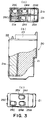
- FIG. 2 illustrated a black ink container shown in Figure 1, and more particularly, a top plan view (a), a partly broken side view (b), and a bottom view (c).
- the cap member and the ink absorbing material are omitted for simplicity of exportation.
- the black ink container 10 comprises a casing 11 which constitutes an ink accommodating portion 16 for the black ink and which is open at the upper end, a cap member 12 closing the opening of the casing 11 and having an air vent (unshown) formed therein, an upper member material 13 which covers the air vent of the cap member 12 and which has a buffer space for preventing the ink leaked through the air vent from flowing to the outside.
- the upper member 13 has an opening (unshown) open to the ambience at a position different from the air vent of the cap member 12 and has a picking portion 13a for facilitating mounting and demounting of the holder 31 ( Figure 1).
- the inside of the casing 21 is partitioned by partition walls 21a, 21b which constitute a T-shape in a cross-section along a horizontal plane (in the state of use) to divide the inside space into three chambers which corresponds the ink receiving tubes of the holder 31, respectively.
- the three chambers constitutes an ink accommodating portion 26Y for the yellow ink, an ink accommodating portion 26C for the cyan ink, and an ink accommodating portion 26M for the magenta ink.
- the air vent of the cap member 22 is provided for each of the ink accommodating portions 26Y, 26C, 26M.
- the casing 21 is provided in the bottom portion with ink supply ports 24Y, 24C, 24M at the positions opposed to the respective ink receiving tubes for the color inks when the color ink container 20 is mounted to the holder 31, and around the ink supply ports 24Y, 24C, 24M, ribs 25Y, 25C, 25M for preventing the ink leakage is formed.
- an ink retaining member for absorbing and retaining the ink and an ink leading member, similarly to the black ink container 10 shown in Figure 2.
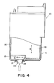
- the description will be made as to the structure of the ink retaining member and the ink leading member and as to the ink supply operation from the ink container, taking the black ink container 10 for instance.
- the description applies also to the color ink container 20.
- the ink leading member 19 has an ink retaining force which is higher than the ink retaining force of the ink retaining member 18.
- the density later the compression is 0.32 g/cm 3 .
- the directions of arrangements of the fibers are substantially perpendicular to the direction of contact to the filter 34 such that ink leading member 19 is further compressed by the contact of the filter 34 (ink receiving tube 33) thereto by which the ink retaining force is enhanced.
- the large of the ink leading member 19 is such as to permit sliding relative to the casing 11, so that it is easily compressed by the filter 34 contacting thereto.
- the direction of arrangement of the fibers are parallel (arrow B) with the direction of contact relative to the filter 34 such that ink retaining member 18 is not easily deformed in the direction of contact.
- the size of the ink retaining member 18 is larger than the inner size of the casing 11 so as to prevent movement in the casing 11.
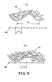
- the ink supply side surface of the ink leading member 19, that is, the contact surface relative to the filter 34 has pits and projections (concave and convex) as shown in Figure in (a) of Figure 5.
- the pitch P2 of the pits and projections formed on the ink supply side surface of the ink leading member 19 is larger than the mesh pitch P1, that is, openings of the filter 34.
- an ink leading member having a directional property is formed through a web lamination method from fibers of the thermoplastic resin material described above. Then, a Teflon mesh having an average opening of approx. 0.5mm is contact to an ink supply side end surface of the ink leading member 19, and the region where the Teflon mesh is contacted to the ink leading member 19 is defeated and melted. By doing so, the pattern of the Teflon mesh is transferred on the ink supply side end surface of the ink leading member 19, so that in the pit-projection configuration is formed on the ink supply side end surface of the ink leading member 19.
- the ink leading member 19 of this embodiment has a directional nature provided by the web lamination method. Particularly, if the direction in which the filers are extended is perpendicular to the direction of contact of the filter, and the curved portion of the fibers can be positively made convex as shown in Figure 5. By doing so, the convex portion of the ink retaining member can be assuredly contacted to the filter when it is contacted into the filter, since the projection contactable to the filter has a resiliency. By the firm formation of the pit-projection configuration using the heat molding, the configuration of the pits and projections called the ink leading member is maintained even if it is contacted into the filter.
- the pitch P2 of the pits and projections formed at the ink supply side end surface of the ink leading member 19 is made larger than the mesh pitch Pl of the filter, by which when the filter 34 is contacted or abutted to the ink leading member 19, as shown in (b) of Figure 5, the pits or concave portions of the ink leading member 19 are not contacted into the filter 34 of the ink leading member 19, but the projections or convex portions are contacted to the filter 34.
- the presence of the spaces are assured between the filter 34 and the ink leading member 19.
- the area in which the fibers constituting the ink leading member 19 partly enter the openings of the filter 34, that is, the ink leading member 19 and the filter 34 are contacted with each other too closely, is significantly decreased.
- the pitches are average pitches. The ink retained in the ink leading member 19 is supplied into the ink receiving tube 33 ( Figure 4) through the opening of the filter 34 through between the fibers constituting the ink leading member 19 in the spaces between the ink leading member 19 and the filter 34.
- the mesh pitch P1 (effective pitch P1) of the filter 34 is substantially the same as that before it is contacted to the ink leading member 19, and therefore, the flow resistance is substantially the same.
- the ink can be stably supplied, even when the ink is to be supplied to the ink jet head at a high flow rate in a high speed ink jet recording apparatus.
- surface of the ink leading member 19 contactable to the filter of the ink receiving tube 33 has a configuration constituting pits and projections, and that configuration is maintained even when the ink leading member 19 is abutted to or press-contacted to the ink receiving tube, more particularly, to the filter.
- the sizes of the openings of the filter 34 and the pits and projections on the ink supply side end surface of the ink leading member 19 are not limited to those given above. As long as the air is not introduced into the gap between the ink leading member 19 and t filter 34, one skilled in the art can easily determines then in consideration of the ink supply property depending on the surface tension, the viscosity of the ink, the wetting property with the ink leading member 19, the wetting property with the filter 34, the required ink flow speed or the like.
- the materials or the structures of the filter 34, the material of the ink leading member 19 are not limited to the examples described above. For example, the ink leading member 19 may be made of porous material rather than the fiber aggregate.
- the example has been taken in which two ink absorbing materials, namely, the ink retaining member 18 and the ink leading member 19.
- the ink absorbing material may be at least contacted to the filter 34 and may comprise one member or three or more members.
- the ink supply side end surface of the ink leading member 19 has the configuration providing the pits and projections, but the pits and projections may be provided on another surface.
- the pits and projections may be provided on the contact surface relative to the ink retaining member 18, in which case the ink retaining member 18 is engaged with the pits and projections so that positional deviation between the ink retaining member 18 and the ink leading member 19 can be suppressed.
- This is desirable from the standpoint of anti-shock property.
- the contact surface relative to the ink retaining member 18 is a side opposed to the ink supply side end surface of the ink leading member 19, the above-described heating can be carried out while sandwiching the ink leading member 19 with the Teflon mesh when the pits and projections are formed on the ink leading member 19, so that operativity in the formation of the pits and projections is improved.
- the sizes of the pits and projections formed on the surface other than the ink supply side end surface can be determined irrespective of the openings of the filter 34.
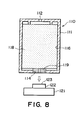
- the stabilized ink supply at the high flow rate is accomplished by reducing the area where the filter 34 and the ink leading member 19 are closely contacted to each other. It is not inevitably the ink supply side end surface of the ink leading member 19 that pit-projection configuration is provided. As shown in Figure 7, the ink supply side end surface of the ink leading member 44 is not subjected to a particular treatment, but the filter 49 is treated for the pit-projection configuration, as shown in Figure 7. By determining the sizes of the pits and projections such that when the ink leading member 44 and the filter 49 are contacted to each other, the filter 49 is not contacted to the ink leading member 44 at the pits or concave portions of the ink leading member 44, but the projections or the convex portions are contacted.
- the invention is employed in an ink jet recording, and the description has been made particularly on the supply of the ink from the ink container to the ink jet head, but the present invention is applicable to a liquid container and liquid supplying system for liquid other than the ink, when the liquid container has therein an absorbing material for absorbing and retaining the liquid, the absorbing material being contacted to the filter when the liquid is supplied to the outside.
- a liquid container includes a container body; a liquid retaining member, provided in the container body, for absorbing and retaining liquid therein, the liquid retaining member having a surface to be contacted by a filter provided at a free end of liquid receiving means to supply the liquid to an outside, wherein the surface of the liquid retaining member is provided with pits and projections, the pits being out of contact with the filter, and the projections being contacted with the filter when the liquid retaining member and the filter are contacted.
Landscapes
- Engineering & Computer Science (AREA)
- Mechanical Engineering (AREA)
- Ink Jet (AREA)
- Fixing For Electrophotography (AREA)
Abstract
Description
Claims (15)
- A liquid container comprising:wherein said surface of said liquid retaining member is provided with pits and projections, the pits being out of contact with the filter, and the projections being contacted with the filter when said liquid retaining member and the filter are contacted.a container body;a liquid retaining member, provided in said container body, for absorbing and retaining liquid therein, said liquid retaining member having a surface to be contacted by a filter provided at a free end of liquid receiving means to supply the liquid to an outside,
- A container according to Claim 1, wherein a pitch of the pits and projections is larger than a pitch of openings of the filter.
- A liquid container according to Claim 1,
wherein said liquid retaining member includes a first liquid retaining member contactable to the filter and a second liquid retaining member, contacted to said first liquid retaining member, for supplying the liquid to said first liquid retaining member, said first liquid retaining member having a liquid retaining force which is larger than a liquid retaining force of said second liquid retaining member. - A liquid container according to Claim 3,
wherein pits and projections are provided on the contact surface of said first liquid retaining member relative to said second liquid retaining member. - A liquid container according to Claim 3,
wherein said first liquid retaining member is made of fibrous material. - A liquid container according to Claim 5,
wherein the fibrous material is thermoplastic resin material. - A liquid container according to Claim 6,
wherein the thermoplastic resin material is polyolefin resin material. - A liquid container according to Claim 6,
wherein the pits and projections are formed by contacting a member having a pattern of pits and projections corresponding to the pits and projections to be formed on the contacts surface of said liquid retaining member to the surface and heating and melting the contacts surface, thus transferring the pit-projection pattern. - A liquid container according to Claim 5,
wherein fibers constituting said first liquid retaining member are extended in a direction substantially perpendicular to a direction of contact of said first liquid retaining member to the filter. - A liquid supplying system comprising:a liquid container having therein a liquid retaining member for absorbing and retaining liquid;liquid receiving means for receiving the liquid from said liquid container through a filter contacted to said liquid retaining member,pits and projections are formed on a surface of said liquid retaining member contactable to said filter or on said filter, the liquid retaining member and the filter being out of contact with each other at the pits and being contacted with each other at the projections.
- A liquid supplying system according to Claim 10, wherein said liquid retaining member includes a first liquid retaining member contactable to the filter and a second liquid retaining member, contacted to said first liquid retaining member, for supplying the liquid to said first liquid retaining member, said first liquid retaining member having a liquid retaining force which is larger than a liquid retaining force of said second liquid retaining member.
- A liquid supplying system according to Claim 11, wherein said first liquid retaining member is made of fibrous material.
- A liquid supplying system according to Claim 12, wherein the fibrous material is thermoplastic resin material. taining member having a liquid retaining force which is larger than a liquid retaining force of said second liquid retaining member.
- A liquid supplying system according to Claim 13, wherein the thermoplastic resin material is polyolefin resin material.
- A liquid supplying system according to Claim 10, 11, 12, 13 or 14, wherein said liquid container and said liquid receiving means are separable from each other.
Applications Claiming Priority (4)
| Application Number | Priority Date | Filing Date | Title |
|---|---|---|---|
| JP2001139976 | 2001-05-10 | ||
| JP2001139976 | 2001-05-10 | ||
| JP2002125908 | 2002-04-26 | ||
| JP2002125908A JP3566708B2 (en) | 2001-05-10 | 2002-04-26 | Liquid storage container and liquid supply system |
Publications (2)
| Publication Number | Publication Date |
|---|---|
| EP1256454A2 true EP1256454A2 (en) | 2002-11-13 |
| EP1256454A3 EP1256454A3 (en) | 2003-06-25 |
Family
ID=26614888
Family Applications (1)
| Application Number | Title | Priority Date | Filing Date |
|---|---|---|---|
| EP02010497A Withdrawn EP1256454A3 (en) | 2001-05-10 | 2002-05-08 | Liquid container and liquid supply system |
Country Status (5)
| Country | Link |
|---|---|
| US (1) | US6746110B2 (en) |
| EP (1) | EP1256454A3 (en) |
| JP (1) | JP3566708B2 (en) |
| KR (1) | KR20020086258A (en) |
| CN (1) | CN1177696C (en) |
Families Citing this family (16)
| Publication number | Priority date | Publication date | Assignee | Title |
|---|---|---|---|---|
| US6942326B2 (en) | 2002-09-30 | 2005-09-13 | Canon Kabushiki Kaisha | Ink tank |
| US7278722B2 (en) * | 2003-11-25 | 2007-10-09 | Brother Kogyo Kabushiki Kaisha | Ink cartridge |
| US7311386B2 (en) * | 2004-06-30 | 2007-12-25 | Lexmark Interntional, Inc. | Die attach methods and apparatus for micro-fluid ejection device |
| US8011768B2 (en) | 2006-08-23 | 2011-09-06 | Canon Kabushiki Kaisha | Ink tank |
| JP5288743B2 (en) * | 2006-08-23 | 2013-09-11 | キヤノン株式会社 | Ink tank and ink jet recording apparatus |
| USD570905S1 (en) | 2006-09-08 | 2008-06-10 | Kenneth Yuen | Ink cartridge |
| US20080165214A1 (en) * | 2007-01-05 | 2008-07-10 | Kenneth Yuen | Ink cartridge fluid flow arrangements and methods |
| US20080204527A1 (en) * | 2007-02-28 | 2008-08-28 | Kenneth Yuen | Ink cartridge |
| JP5838572B2 (en) * | 2011-03-17 | 2016-01-06 | セイコーエプソン株式会社 | printer |
| JP6308989B2 (en) | 2015-09-30 | 2018-04-11 | キヤノン株式会社 | Liquid storage container and liquid discharge device |
| JP6723729B2 (en) | 2015-11-17 | 2020-07-15 | キヤノン株式会社 | Liquid storage container and method of manufacturing liquid storage container |
| JP6624905B2 (en) | 2015-11-26 | 2019-12-25 | キヤノン株式会社 | Liquid container and liquid level detector |
| US10391776B2 (en) | 2015-11-30 | 2019-08-27 | Canon Kabushiki Kaisha | Liquid storage container and printing apparatus |
| JP7532055B2 (en) | 2020-03-24 | 2024-08-13 | キヤノン株式会社 | Liquid Supply Unit |
| JP7504641B2 (en) | 2020-03-27 | 2024-06-24 | キヤノン株式会社 | Liquid ejection device |
| JP7520574B2 (en) | 2020-05-22 | 2024-07-23 | キヤノン株式会社 | LIQUID CARTRIDGE AND LIQUID EJECTION DEVICE |
Citations (1)
| Publication number | Priority date | Publication date | Assignee | Title |
|---|---|---|---|---|
| JPH08230207A (en) | 1995-03-01 | 1996-09-10 | Canon Inc | Ink tank and manufacturing method thereof |
Family Cites Families (8)
| Publication number | Priority date | Publication date | Assignee | Title |
|---|---|---|---|---|
| JP2702808B2 (en) * | 1990-08-30 | 1998-01-26 | シャープ株式会社 | Ink supply device and ink receiving unit |
| DE69118489T2 (en) * | 1990-11-30 | 1996-08-14 | Canon Kk | Ink tank and recording head with such a tank |
| JP3209992B2 (en) | 1990-11-30 | 2001-09-17 | キヤノン株式会社 | Ink supply container and inkjet recording head |
| DE69331791T2 (en) * | 1993-07-20 | 2002-10-10 | Canon K.K., Tokio/Tokyo | An ink jet recording apparatus which uses a color cartridge with an ink inducing element |
| US5657065A (en) * | 1994-01-03 | 1997-08-12 | Xerox Corporation | Porous medium for ink delivery systems |
| ES2162881T3 (en) | 1994-07-06 | 2002-01-16 | Canon Kk | INK CONTAINER, INK JET HEAD WITH INK CONTAINER, APPARATUS FOR PRINTING BY INK JETS WITH INK CONTAINER AND MANUFACTURING METHOD OF THE INK. |
| JP3610258B2 (en) | 1999-01-27 | 2005-01-12 | キヤノン株式会社 | Negative pressure generating member manufacturing method, negative pressure generating member using the manufacturing method, and ink tank |
| US6629758B2 (en) * | 2000-04-19 | 2003-10-07 | Canon Kabushiki Kaisha | Joint device, ink jet recording apparatus having the same, and ink supplying device and method |
-
2002
- 2002-04-26 JP JP2002125908A patent/JP3566708B2/en not_active Expired - Fee Related
- 2002-05-03 US US10/137,390 patent/US6746110B2/en not_active Expired - Lifetime
- 2002-05-08 EP EP02010497A patent/EP1256454A3/en not_active Withdrawn
- 2002-05-09 KR KR1020020025440A patent/KR20020086258A/en not_active Abandoned
- 2002-05-10 CN CNB021191549A patent/CN1177696C/en not_active Expired - Fee Related
Patent Citations (1)
| Publication number | Priority date | Publication date | Assignee | Title |
|---|---|---|---|---|
| JPH08230207A (en) | 1995-03-01 | 1996-09-10 | Canon Inc | Ink tank and manufacturing method thereof |
Also Published As
| Publication number | Publication date |
|---|---|
| JP3566708B2 (en) | 2004-09-15 |
| JP2003025605A (en) | 2003-01-29 |
| CN1177696C (en) | 2004-12-01 |
| KR20020086258A (en) | 2002-11-18 |
| EP1256454A3 (en) | 2003-06-25 |
| US20020167573A1 (en) | 2002-11-14 |
| US6746110B2 (en) | 2004-06-08 |
| CN1385307A (en) | 2002-12-18 |
Similar Documents
| Publication | Publication Date | Title |
|---|---|---|
| US6746110B2 (en) | Liquid container and liquid supply system | |
| EP1403064B1 (en) | Ink container, recording head and recording device using same | |
| JP3667296B2 (en) | Ink tank | |
| JP3667295B2 (en) | Ink tank | |
| JP3278410B2 (en) | Liquid container, method of manufacturing the container, package of the container, ink jet head cartridge integrating the container with a recording head, and liquid discharge recording apparatus | |
| EP0894630B1 (en) | Ink container, ink absorbing member usable with the ink container and manufacturing method of the ink container | |
| JP5552931B2 (en) | Liquid container and liquid ejection system | |
| US6102533A (en) | Ink container, ink container holder for removably holding ink container, and ink container cap | |
| KR100235158B1 (en) | Liquid container for an ink jet recording apparatus | |
| JP5552932B2 (en) | Liquid container and liquid ejection system | |
| US20080106582A1 (en) | Liquid tank | |
| JP3564895B2 (en) | Ink tank and inkjet recording device | |
| JP2014097577A (en) | Cap and liquid storage container | |
| US7396117B2 (en) | Liquid container and liquid ejecting cartridge | |
| JP6056723B2 (en) | Cartridge and cap | |
| KR100612450B1 (en) | Ink Cartridges for Wide Array Heads | |
| JP2001001539A (en) | Liquid supply system, liquid supply container and negative pressure generating member storage container used in the system | |
| JP3258311B2 (en) | Ink tank and ink jet device | |
| JP4579446B2 (en) | Liquid storage container | |
| JP4666805B2 (en) | Ink tank | |
| CA2229871C (en) | Liquid container for ink jet head | |
| JP2015229290A (en) | Liquid supply unit | |
| JP2001105621A (en) | Liquid storage container, package of the container, ink jet head cartridge integrating recording container and recording head, and recording apparatus | |
| HK1060546A (en) | Ink container, recording head and recording device using same |
Legal Events
| Date | Code | Title | Description |
|---|---|---|---|
| PUAI | Public reference made under article 153(3) epc to a published international application that has entered the european phase |
Free format text: ORIGINAL CODE: 0009012 |
|
| 17P | Request for examination filed |
Effective date: 20020508 |
|
| AK | Designated contracting states |
Kind code of ref document: A2 Designated state(s): AT BE CH CY DE DK ES FI FR GB GR IE IT LI LU MC NL PT SE TR |
|
| AX | Request for extension of the european patent |
Free format text: AL;LT;LV;MK;RO;SI |
|
| PUAL | Search report despatched |
Free format text: ORIGINAL CODE: 0009013 |
|
| AK | Designated contracting states |
Designated state(s): AT BE CH CY DE DK ES FI FR GB GR IE IT LI LU MC NL PT SE TR |
|
| AX | Request for extension of the european patent |
Extension state: AL LT LV MK RO SI |
|
| RIC1 | Information provided on ipc code assigned before grant |
Ipc: 7D 01F 6/04 B Ipc: 7B 41J 2/175 A |
|
| AKX | Designation fees paid |
Designated state(s): AT BE CH CY DE DK ES FI FR GB GR IE IT LI LU MC NL PT SE TR |
|
| 17Q | First examination report despatched |
Effective date: 20040317 |
|
| STAA | Information on the status of an ep patent application or granted ep patent |
Free format text: STATUS: THE APPLICATION IS DEEMED TO BE WITHDRAWN |
|
| 18D | Application deemed to be withdrawn |
Effective date: 20050704 |