EP1256296A2 - Adjustable spring-driven pusher device for a merchandise dispenser - Google Patents
Adjustable spring-driven pusher device for a merchandise dispenser Download PDFInfo
- Publication number
- EP1256296A2 EP1256296A2 EP02253277A EP02253277A EP1256296A2 EP 1256296 A2 EP1256296 A2 EP 1256296A2 EP 02253277 A EP02253277 A EP 02253277A EP 02253277 A EP02253277 A EP 02253277A EP 1256296 A2 EP1256296 A2 EP 1256296A2
- Authority
- EP
- European Patent Office
- Prior art keywords
- pusher
- arbor
- end portion
- spring
- coiled
- Prior art date
- Legal status (The legal status is an assumption and is not a legal conclusion. Google has not performed a legal analysis and makes no representation as to the accuracy of the status listed.)
- Granted
Links
- 238000004804 winding Methods 0.000 claims abstract description 32
- 230000007246 mechanism Effects 0.000 claims abstract description 28
- 239000002184 metal Substances 0.000 claims abstract description 10
- 238000000034 method Methods 0.000 claims description 9
- 230000003247 decreasing effect Effects 0.000 abstract description 2
- 229910000831 Steel Inorganic materials 0.000 description 4
- 239000010959 steel Substances 0.000 description 4
- 230000000712 assembly Effects 0.000 description 3
- 238000000429 assembly Methods 0.000 description 3
- 235000015496 breakfast cereal Nutrition 0.000 description 2
- 238000004519 manufacturing process Methods 0.000 description 2
- 230000004075 alteration Effects 0.000 description 1
- 238000013459 approach Methods 0.000 description 1
- 238000012986 modification Methods 0.000 description 1
- 230000004048 modification Effects 0.000 description 1
- 239000010705 motor oil Substances 0.000 description 1
- 235000014214 soft drink Nutrition 0.000 description 1
- 230000007704 transition Effects 0.000 description 1
Images


Classifications
-
- A—HUMAN NECESSITIES
- A47—FURNITURE; DOMESTIC ARTICLES OR APPLIANCES; COFFEE MILLS; SPICE MILLS; SUCTION CLEANERS IN GENERAL
- A47F—SPECIAL FURNITURE, FITTINGS, OR ACCESSORIES FOR SHOPS, STOREHOUSES, BARS, RESTAURANTS OR THE LIKE; PAYING COUNTERS
- A47F1/00—Racks for dispensing merchandise; Containers for dispensing merchandise
- A47F1/04—Racks or containers with arrangements for dispensing articles, e.g. by means of gravity or springs
- A47F1/12—Racks or containers with arrangements for dispensing articles, e.g. by means of gravity or springs dispensing from the side of an approximately horizontal stack
- A47F1/125—Racks or containers with arrangements for dispensing articles, e.g. by means of gravity or springs dispensing from the side of an approximately horizontal stack with an article-pushing device
- A47F1/126—Racks or containers with arrangements for dispensing articles, e.g. by means of gravity or springs dispensing from the side of an approximately horizontal stack with an article-pushing device the pushing device being urged by spring means
Definitions
- the present invention relates to an adjustable spring-driven pusher device for use on a forward feeding merchandise display shelf to dispense articles one by one from a front, or dispensing end, of the shelf, and more particularly, the present invention relates to a spring-driven pusher device that can be set to provide a predetermined amount of pushing force adjustable within a range of pushing forces.
- Many stores store and display products on shelves from which purchasers can select and remove one or more of the products from the shelves.
- Such shelves are typically provided with a forward feeding pusher device so that a substantially horizontal stacked low of identical products located in front of the pusher device is biased toward the front end, or dispensing end, of the shelf to force the products remaining in the row to be pushed forward when one of the products from the front end of the shelf is removed.
- the pusher can extend upwardly from a track located below the products, downwardly from a track located above the products, or laterally from a track extending adjacent the sides of the products.
- the pusher device can extend from a substantially vertical track and be utilized to up-feed, or down feed, a vertically stacked column of products.
- a spring providing a desired amount of pushing force must be selected and installed in the spring-driven pusher device.
- a spring sufficiently strong to forward feed relatively heavy items, or items which resist sliding may be too strong for use in feeding relatively lightweight or readily slidable items, and conversely, a spring sufficient to forward feed relatively lightweight items may not be capable of pushing relatively heavy items.
- the Suttles patent discloses a pusher device driven by a positive gradient, ie. variable force, self-coiling metal spring.
- the Suttles patent states that a positive gradient spring is preferred since it exerts greater force when fully extended and less force as the spring becomes further retracted.
- the Suttles patent discloses the use of an adjustable angled pusher plate which can be utilized to adjust the pushing force provided by the spring-driven pusher device.
- the Suttles patent states that the force is maximized when the plate extends perpendicular from the track and is reduced when the plate is bent forward to reduce the angle formed between the plate and the track. See column 7, line 44, to column 8, line 2, of the Suttles patent.
- the Spamer patent discloses the use of a self-coiling metal spring having a two-stage structure.
- the spring has a coiled end portion with innermost windings acting as a constant force spring and outermost windings acting as a variable force spring. See FIG. 12 and column 7, lines 6-65, of the Spamer patent.
- the purpose of the constant force spring inner windings is to prevent excessive force from being exerted on a fully loaded row of articles.
- a primary object of the present invention is to provide a novel universal spring-driven pusher device which can be utilized to forwardfeed, up-feed, top-feed, or side-feed merchandise in a dispenser for products within a great range of weights, sizes, shapes, and surface textures and which does not require replacement when one type of merchandise in the dispenser is replaced with another type of merchandise significantly different in weight, size, shape and/or surface texture.
- Another object of the present invention is to provide a novel spring-driven pusher device which enables accurate incremental adjustment of pushing force within a wide range of forces.
- a further object of the present invention is to provide a method of adjusting the pushing force provided by a spring-driven pusher device, the method should require only a minimum of effort and skill and permit ready adjustment in a minimum of time.
- a still further object of the present invention is to provide an adjustable spring-driven pusher device which can be readily manufactured in a cost efficient manner.
- the present invention provides a spring-driven pusher device for an article dispenser that includes an elongate track having a dispensing end and an opposite end and an elongate surface for positioning a row of articles for movement therealong between the dispensing end and the opposite end of the track.
- the track can be disposed parallel or perpendicular to the horizontal or at any angle relative to the horizontal and can be positioned below, above, or adjacent the sides of the articles being dispensed.
- a pusher extends outwardly from the track and is connected to the track for movement lengthwise along the track between the dispensing and opposite ends for urging the row of articles toward the dispensing end of the track.
- a flat metal self-coiling spring such as a steel variable force spring or a steel power spring, or a flat elongate strip of metal which is placed in a coiled condition, exerts a force on the pusher to urge the pusher toward the dispensing end of the track.
- the spring, or strip has a coiled end portion which is carried on the pusher and an opposite uncoiled end portion which is connected to the track.
- the spring, or strip has a coiled end portion which is connected to the track and an uncoiled end portion which is carried on the pusher.
- the coiled end portion includes multiple windings under tension about an axis and a terminal end located adjacent the axis.
- a slotted arbor extends along the axis of the coiled end portion and is connected to the terminal end of the coiled end portion.
- the terminal end portion can be connected to the arbor with a screw or like fastening device.
- the arbor is rotatably mounted to one of the pusher or the track so that the tension of the windings of the coiled end portion is adjustable by rotation of the arbor.
- the pushing force provided by the spring, or strip, of the pushing device is readily adjustable in a store by store personnel by increasing or reducing the tension of the windings of the coiled end portion of the spring, or strip.
- a method for loading a forward, side, top, or up feeding merchandising apparatus.
- the method includes the step of positioning a row, or column, of articles in front of, or on top of, a pusher device.
- the pusher extends transversely to a path of movement of the articles for movement lengthwise along a track between the dispensing end and opposite end of the track and urges the articles toward the dispensing end.
- the method includes the step of setting the pusher to provide a desired amount of pushing force.
- the pusher is connected to a self-coiling variable force spring, a self-coiling power spring or a flat strip of metal positioned in a coiled condition.
- the self-coiling spring, or strip has a coiled end portion with multiple windings under tension
- the step of setting the pusher includes adjusting the tension of the windings of the coiled end portion of the spring, or strip.
- the pusher includes a rotatable arbor extending along an axis of the coiled end portion, and a terminal end of the coiled end portion is mounted on the arbor for rotation with the arbor.
- the step of setting the pusher includes rotating the arbor to adjust the tension of the windings of the coiled end portion.
- the step of setting the pusher includes locking the arbor in a condition which prevents rotation of the arbor about the axis of the coiled end portion after a desired tension of the windings is set.
- the present invention is a spring-driven pusher device 10 for use on a shelf 12, such as illustrated in FIG. 2, for forward feeding merchandise (not shown) stored and displayed on the shelf 12.
- merchandise not shown
- several boxes of a particular breakfast cereal, or like articles can be positioned in a single file row one behind the other on the shelf 12 such that a leading box is located at a front dispensing end of the shelf 12. Thereafter, the leading box can be removed from the shelf 12 by a purchaser, and the pusher device 10 will urge the remaining boxes forward to provide a new leading box adjacent the front end of the shelf 12.
- the pusher device 10 of the present invention can also be utilized in up-feeding, side-feeding, and top-feeding merchandise dispensers.
- the illustrated embodiment of the present invention includes an elongate track 14 having a front dispensing end 16, an opposite rear end 18 and an elongate surface 14a facing the row of articles.
- the track 14 is removably mountable to a shelf 12, and articles are positioned on the track 14 in a row such that the leading article is located adjacent the front end 16 and the rearmost article is located adjacent the rear end 18 of the track 14.
- the track 14 can be mounted to extend above, or to the side of, the stacked articles on the substantially horizontal, or slightly angled, shelf 12, or can be mounted vertically or at a steep angle relative to the horizontal for up-feeding a column of stacked articles to a dispensing end.
- the pusher device 10 is mounted on the track 14 in a manner which permits movement of the pusher device 10 between the dispensing end 16 and the opposite end 18 of the track 14.
- the pusher device 10 is moved rearwardly, or toward the opposite end 18, to load a row of articles on the shelf 12 and is resiliently biased forward, or toward the dispensing end 16, by a spring/strip 20, as will be discussed in greater detail.
- the track 14 includes an elongate slot 22 extending longitudinally, or lengthwise, on the track 14 and utilized to capture a flange 24 extending from the pusher device 10.
- the pusher device 10 engages the surface 14a of the track 14 and is free to slide in a straight path between the front dispensing and opposite rear ends, 16 and 18, of the track 14.
- the pusher device 110 as illustrated in FIG. 5 has a pair of side flanges 26 and 28 which grip about the outer side edges 30 and 32 of the track 114. This configuration also permits the pusher device to slide in a straight path between the ends of the track.
- Other contemplated alternatives include the use of rollers, ball bearings, wheels or the like to permit the pusher device to readily move across the track.
- the pusher device 10 includes a pusher plate 34 which extends outwardly, or transversely, from the track 14 and which has a front surface 36 that engages the rearmost article of the row, or column, of stacked articles.
- the pusher plate 34 also includes a spring retaining structure 38 which permits a coiled end portion 40 of a self-coiling spring, or strip, 20 to be carried on a rear side 42 of the pusher plate 34.
- the coiled end portion 40 of the spring 20 could be mounted on the track 14, and the free end 50 of the spring 20 opposite from the coiled end portion 40 could be attached to the pusher plate 34.
- the spring retaining structure 38 is located on the pusher plate 34 and includes a pair of spaced apart, parallel retaining flanges, 44 and 46, which extend rearwardly from the rear side 42 of the pusher plate 34.
- a terminal end 60 of the coiled end portion 40 is mounted on an arbor 48 which extends transversely with respect to the retaining flanges, 44 and 46, and which is mounted to the retaining flanges, 44 and 46.
- the terminal end 60 and coiled end portion 40 of the illustrated embodiment is carried on the pusher plate 34 adjacent the rear side 42 of the pusher plate 34 between the retaining flanges 44 and 46 and is wound about the arbor 48.
- the free end 50 of an uncoiled portion 52 of the spring 20 remote from the coiled end portion 40 is connected to the track 14 adjacent its dispensing end 16. Therefore, when the pusher plate 34 is moved rearwardly on the track 14, the spring uncoils and applies a force on the pusher plate 34 in a direction toward the front dispensing end 16 of the track 14.
- the spring/strip, or force exerting mechanism, 20 is a flat metal self-coiling spring or a flat strip of metal which is placed in a coiled condition.
- a metal self-coiling spring include a steel variable force spring and a steel power spring.
- the pushing force provided by the spring/strip 20 should gradually reduce as the pusher plate approaches the front end 16 of the track 14 and as the spring/strip 20 transitions from being fully extended in a non-coiled condition to being fully retracted in a coiled condition.
- a spring advantageously exerts a maximum force when the shelf 12 is fully loaded with a full row of articles and exerts a progressively reduced amount of force as the leading articles of the row are removed one by one until all the articles are removed from the shelf 12.
- the maximum and minimum amount of pushing force exerted by the spring depends on the particular strength of spring selected and installed on the pusher device.
- the prior art devices require changes to the merchandise assembly and spring when a different article having a different size, shape, weight and/or surface texture is stored on the shelf.
- heavier articles, or articles that do not readily slide across the shelf due to friction require stronger springs and greater pushing forces than lightweight articles, or articles that are capable of readily sliding across the shelf with a relatively light amount of force.
- One of the novel features of the present invention is that it has a spring adjustment mechanism 54 for adjusting the pushing force provided by the spring/strip 20 so that a given pusher device 10 having a single spring/strip 20 can be utilized in connection with many different products which may have significantly different weights, surface textures, shapes and sizes.
- the pushing force provided by the pusher plate 10 of the present invention can be precisely set to deliver a desired pushing force within a wide range of forces.
- the same pusher device 10 can be set to properly feed a row, or column, of relatively heavy articles toward the dispensing end 16, and then, reset to properly feed a row, or column, of relatively lightweight articles toward the dispensing end 16.
- the illustrated embodiment of the spring adjustment mechanism 54 of the present invention includes the use of a rotatable arbor 48 and an arbor locking mechanism 56 as will be discussed.
- the arbor 48 extends through the central axis "A"of the coiled end portion 40 of the spring/strip 20.
- the coiled end portion 40 includes a plurality of windings 58 about the arbor 48 and has a terminal end 60 located adjacent to axis "A".
- the terminal end 60 is inserted into a slot 62 in the arbor 48 for rotation therewith.
- the terminal end can be connected to the arbor with a screw or like fastener, or can be connected to a stud extending from the arbor.
- the arbor 48 is rotatably mounted to the spring retaining flanges, 44 and 46, when the arbor is rotated clockwise, or counter clockwise, relative to axis "A", the windings 58 are caused to loosen or tighten.
- the windings 58 will progressively become more tightly wound onto the arbor 48. Conversely, if the arbor 48 in FIG. 3 is rotated clockwise, the windings 58 will be less tightly wound on the arbor 48.
- a pushing device having a tightly wound coiled end portion exerts a greater amount of pushing force than a pushing device with a loosely wound coiled end portion.
- the pushing device 10 can be set with a desired amount of pushing force by tightening or loosening the tension of the windings 58 of the coiled end portion 40.
- the arbor locking mechanism 56 is utilized to prevent the arbor 48 from rotating so that the spring 20 exerts the desired set force.
- the arbor 48 extends through the spring retaining flanges, 44 and 46, and has opposite end wall flanges, 64 and 66, located exterior of the spring retaining flanges, 44 and 46. This structure mounts the arbor 48 to the pusher plate 34 and permits the arbor 48 to be rotated for increasing and decreasing the tension of the windings 58 of the coiled end 40 of the spring.
- the retaining flange 46 includes a series of apertures 68 and the end wall flange 66 includes at least one locking projection 70 which can be cooperatively received in one of the apertures 68 for preventing further rotation of the arbor 48.
- a spring 72 or the like is located between the retaining flange 44 and the end wall flange 64 to resiliently bias the arbor 48 in a direction which prevents unwanted removal of the locking projection 70 from the aperture 68.
- locking mechanism 56 While a particular locking mechanism 56 is illustrated and discussed, other locking mechanism can be utilized. For example, any amount of apertures 68 and projections 70 can be utilized, and the relative location of the apertures 68, projections 70, and spring 72 on the retaining flanges, 44 and 46, and end wall flanges, 64 and 66, can be altered. In addition, a ratchet-type locking mechanism, a friction-fit type locking mechanism, or any other type of locking mechanism can be utilized. The illustrated locking mechanism 56 merely provides one example. Further, the locking mechanism can be designed to lock the arbor 48 at discreet intervals of adjustment, or can provide continuous adjustment and lock at any position.
- an employee of a store responsible for loading the shelf 12 with articles adjusts the tension of the spring/strip 20 as desired to provide an appropriate amount of force to feed articles toward the dispensing end 16. If the pushing force is determined to be too weak for a particular row or column of articles, the arbor 48 can be rotated to increase the tension of the windings 58 and can then be locked into position to hold the selected tension. Alternatively, if the pushing force is determined to be too strong for a particular row or column of articles, the arbor 48 can be rotated to reduce the tension of the windings 58 and then locked into position to hold the selected tension.
- the articles can be positioned onto the shelf 12 with the pushing plate 34 engaging a rearmost article in the row for feeding the row of articles to the dispensing end 16.
- the pusher device provides a universal pusher device for use in forward, side, top and up feeding various products regardless of the amount of pushing force required.
- the pushing force can be readily adjusted as needed, and can be accurately set to ensure proper feeding of a stacked row or column of articles to a dispensing end of the merchandise dispenser.
- the pushing force can be set in a minimum of time with a minimum of effort, and the manufacture of the pushing device can be accomplished in a cost effective manner.
Landscapes
- Vending Machines For Individual Products (AREA)
- Freezers Or Refrigerated Showcases (AREA)
Abstract
Description
- The present invention relates to an adjustable spring-driven pusher device for use on a forward feeding merchandise display shelf to dispense articles one by one from a front, or dispensing end, of the shelf, and more particularly, the present invention relates to a spring-driven pusher device that can be set to provide a predetermined amount of pushing force adjustable within a range of pushing forces.
- Many stores, particularly retail stores, outlet stores and the like, store and display products on shelves from which purchasers can select and remove one or more of the products from the shelves. Such shelves are typically provided with a forward feeding pusher device so that a substantially horizontal stacked low of identical products located in front of the pusher device is biased toward the front end, or dispensing end, of the shelf to force the products remaining in the row to be pushed forward when one of the products from the front end of the shelf is removed. In such a forward feeding device, the pusher can extend upwardly from a track located below the products, downwardly from a track located above the products, or laterally from a track extending adjacent the sides of the products. Alternatively, the pusher device can extend from a substantially vertical track and be utilized to up-feed, or down feed, a vertically stacked column of products.
- Examples of such merchandiser assemblies are disclosed in U.S. Patent Nos.: 4,303,162 issued to Suttles; 5,634,564 issued to Spamer et al.; 5,012,936 issued to Crum; 5,562,217 issued to Salveson et al.; 5,878,895 issued to Springs; and 5,131,563 issued to Yablans.
- One problem presented by the use of such merchandiser assemblies is that the products being stored and displayed often range significantly in size, shape, surface texture, and weight. For example, some products are lightweight and sold in relatively small rectangular boxes or cartons (ie. breakfast cereals), whereas other products may be relatively heavy and be packaged in plastic containers or the like (ie. bottles of motor oil). Thus, depending on which product is to be stored and displayed on a particular shelf, a spring providing a desired amount of pushing force must be selected and installed in the spring-driven pusher device. For example, a spring sufficiently strong to forward feed relatively heavy items, or items which resist sliding, may be too strong for use in feeding relatively lightweight or readily slidable items, and conversely, a spring sufficient to forward feed relatively lightweight items may not be capable of pushing relatively heavy items.
- Therefore, there exists a need for a universal spring-driven pusher device which can provide a selected pushing force within a wide range of forces so that the same spring-driven pusher device can be used in connection with products which range significantly in size, shape, surface texture and weight.
- U.S. Patent No. 4,303,162 issued to Suttles, cited above, discloses a forward feeding merchandising device for soft drink bottles. The Suttles patent discloses a pusher device driven by a positive gradient, ie. variable force, self-coiling metal spring. The Suttles patent states that a positive gradient spring is preferred since it exerts greater force when fully extended and less force as the spring becomes further retracted. In addition, the Suttles patent discloses the use of an adjustable angled pusher plate which can be utilized to adjust the pushing force provided by the spring-driven pusher device. To this end, the Suttles patent states that the force is maximized when the plate extends perpendicular from the track and is reduced when the plate is bent forward to reduce the angle formed between the plate and the track. See column 7,
line 44, to column 8, line 2, of the Suttles patent. - U.S. Patent No. 5,634,564 issued to Spamer et al., cited above, discloses another spring-driven pusher device for dispensing articles. The Spamer patent discloses the use of a self-coiling metal spring having a two-stage structure. The spring has a coiled end portion with innermost windings acting as a constant force spring and outermost windings acting as a variable force spring. See FIG. 12 and column 7, lines 6-65, of the Spamer patent. According to Spamer, the purpose of the constant force spring inner windings is to prevent excessive force from being exerted on a fully loaded row of articles.
- Although the above referenced merchandiser assemblies having spring-driven pusher devices may be satisfactory for their intended purposes, there is a need for a novel universal spring-driven pusher device which permits ready adjustment of the pushing force provided by the pusher device so that, when a shelf is utilized to store and display a different product type, the same pusher device and spring can be utilized regardless of the shape, weight, surface texture, or size of the newly stored and displayed product. Further, the pushing force should be capable of ready and precise adjustment within fine increments so that the universal spring-driven pusher device can be set to provide a proper amount of pushing force specifically required for the selected product. In addition, the spring-loaded pusher device should be inexpensive to manufacture and easy to adjust.
- With the foregoing in mind, a primary object of the present invention is to provide a novel universal spring-driven pusher device which can be utilized to forwardfeed, up-feed, top-feed, or side-feed merchandise in a dispenser for products within a great range of weights, sizes, shapes, and surface textures and which does not require replacement when one type of merchandise in the dispenser is replaced with another type of merchandise significantly different in weight, size, shape and/or surface texture.
- Another object of the present invention is to provide a novel spring-driven pusher device which enables accurate incremental adjustment of pushing force within a wide range of forces.
- A further object of the present invention is to provide a method of adjusting the pushing force provided by a spring-driven pusher device, the method should require only a minimum of effort and skill and permit ready adjustment in a minimum of time.
- A still further object of the present invention is to provide an adjustable spring-driven pusher device which can be readily manufactured in a cost efficient manner.
- More specifically, the present invention provides a spring-driven pusher device for an article dispenser that includes an elongate track having a dispensing end and an opposite end and an elongate surface for positioning a row of articles for movement therealong between the dispensing end and the opposite end of the track. The track can be disposed parallel or perpendicular to the horizontal or at any angle relative to the horizontal and can be positioned below, above, or adjacent the sides of the articles being dispensed. A pusher extends outwardly from the track and is connected to the track for movement lengthwise along the track between the dispensing and opposite ends for urging the row of articles toward the dispensing end of the track. Preferably, a flat metal self-coiling spring, such as a steel variable force spring or a steel power spring, or a flat elongate strip of metal which is placed in a coiled condition, exerts a force on the pusher to urge the pusher toward the dispensing end of the track. To this end, the spring, or strip, has a coiled end portion which is carried on the pusher and an opposite uncoiled end portion which is connected to the track. Alternatively, the spring, or strip, has a coiled end portion which is connected to the track and an uncoiled end portion which is carried on the pusher. The coiled end portion includes multiple windings under tension about an axis and a terminal end located adjacent the axis. Preferably, a slotted arbor extends along the axis of the coiled end portion and is connected to the terminal end of the coiled end portion. Alternatively, the terminal end portion can be connected to the arbor with a screw or like fastening device.
- The arbor is rotatably mounted to one of the pusher or the track so that the tension of the windings of the coiled end portion is adjustable by rotation of the arbor. Thus, the pushing force provided by the spring, or strip, of the pushing device is readily adjustable in a store by store personnel by increasing or reducing the tension of the windings of the coiled end portion of the spring, or strip.
- According to another aspect of the present invention, a method is provided for loading a forward, side, top, or up feeding merchandising apparatus. The method includes the step of positioning a row, or column, of articles in front of, or on top of, a pusher device. The pusher extends transversely to a path of movement of the articles for movement lengthwise along a track between the dispensing end and opposite end of the track and urges the articles toward the dispensing end. In addition, the method includes the step of setting the pusher to provide a desired amount of pushing force. To this end, the pusher is connected to a self-coiling variable force spring, a self-coiling power spring or a flat strip of metal positioned in a coiled condition.
- The self-coiling spring, or strip, has a coiled end portion with multiple windings under tension, and the step of setting the pusher includes adjusting the tension of the windings of the coiled end portion of the spring, or strip. Preferably, the pusher includes a rotatable arbor extending along an axis of the coiled end portion, and a terminal end of the coiled end portion is mounted on the arbor for rotation with the arbor. The step of setting the pusher includes rotating the arbor to adjust the tension of the windings of the coiled end portion. In addition, preferably the step of setting the pusher includes locking the arbor in a condition which prevents rotation of the arbor about the axis of the coiled end portion after a desired tension of the windings is set.
- The foregoing and other objects, features and advantages of the present invention should become apparent from the following description when taken in conjunction with the accompanying drawings, in which:
- FIG. 1 is a perspective view of a spring-driven pusher device according to the present invention;
- FIG. 2 is a partially cut-away front elevational view of the spring-driven pusher device illustrated in FIG. 1 mounted on a shelf;
- FIG. 3 is a cross-sectional view of the spring-driven pusher device illustrated in
FIG. 2 along
line 3--3; - FIG. 4 is a cross-sectional view of the spring-driven pusher device illustrated in FIG. 1 along line 4--4; and
- FIG. 5 is a rear elevational view of an alternate embodiment of a spring-driven pusher device according to the present invention and mounted on a shelf.
-
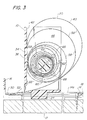
- As illustrated in FIG. 1, the present invention is a spring-driven
pusher device 10 for use on ashelf 12, such as illustrated in FIG. 2, for forward feeding merchandise (not shown) stored and displayed on theshelf 12. For example, several boxes of a particular breakfast cereal, or like articles, can be positioned in a single file row one behind the other on theshelf 12 such that a leading box is located at a front dispensing end of theshelf 12. Thereafter, the leading box can be removed from theshelf 12 by a purchaser, and thepusher device 10 will urge the remaining boxes forward to provide a new leading box adjacent the front end of theshelf 12. Although not illustrated, thepusher device 10 of the present invention can also be utilized in up-feeding, side-feeding, and top-feeding merchandise dispensers. - Similar to the prior art, the illustrated embodiment of the present invention includes an
elongate track 14 having a front dispensingend 16, an oppositerear end 18 and anelongate surface 14a facing the row of articles. Thetrack 14 is removably mountable to ashelf 12, and articles are positioned on thetrack 14 in a row such that the leading article is located adjacent thefront end 16 and the rearmost article is located adjacent therear end 18 of thetrack 14. Alternatively, thetrack 14 can be mounted to extend above, or to the side of, the stacked articles on the substantially horizontal, or slightly angled,shelf 12, or can be mounted vertically or at a steep angle relative to the horizontal for up-feeding a column of stacked articles to a dispensing end. - The
pusher device 10 is mounted on thetrack 14 in a manner which permits movement of thepusher device 10 between the dispensingend 16 and theopposite end 18 of thetrack 14. Thus, thepusher device 10 is moved rearwardly, or toward theopposite end 18, to load a row of articles on theshelf 12 and is resiliently biased forward, or toward the dispensingend 16, by a spring/strip 20, as will be discussed in greater detail. As best illustrated in FIGs. 1 and 4, thetrack 14 includes anelongate slot 22 extending longitudinally, or lengthwise, on thetrack 14 and utilized to capture aflange 24 extending from thepusher device 10. In this manner, thepusher device 10 engages thesurface 14a of thetrack 14 and is free to slide in a straight path between the front dispensing and opposite rear ends, 16 and 18, of thetrack 14. Alternatively, thepusher device 110 as illustrated in FIG. 5 has a pair ofside flanges track 114. This configuration also permits the pusher device to slide in a straight path between the ends of the track. Other contemplated alternatives include the use of rollers, ball bearings, wheels or the like to permit the pusher device to readily move across the track. - The
pusher device 10 includes apusher plate 34 which extends outwardly, or transversely, from thetrack 14 and which has afront surface 36 that engages the rearmost article of the row, or column, of stacked articles. Thepusher plate 34 also includes aspring retaining structure 38 which permits acoiled end portion 40 of a self-coiling spring, or strip, 20 to be carried on arear side 42 of thepusher plate 34. Alternatively, thecoiled end portion 40 of thespring 20 could be mounted on thetrack 14, and thefree end 50 of thespring 20 opposite from thecoiled end portion 40 could be attached to thepusher plate 34. - In the illustrated preferred embodiment, the
spring retaining structure 38 is located on thepusher plate 34 and includes a pair of spaced apart, parallel retaining flanges, 44 and 46, which extend rearwardly from therear side 42 of thepusher plate 34. Aterminal end 60 of thecoiled end portion 40 is mounted on anarbor 48 which extends transversely with respect to the retaining flanges, 44 and 46, and which is mounted to the retaining flanges, 44 and 46. Thus, theterminal end 60 andcoiled end portion 40 of the illustrated embodiment is carried on thepusher plate 34 adjacent therear side 42 of thepusher plate 34 between the retainingflanges arbor 48. - Preferably, the
free end 50 of an uncoiledportion 52 of thespring 20 remote from thecoiled end portion 40 is connected to thetrack 14 adjacent its dispensingend 16. Therefore, when thepusher plate 34 is moved rearwardly on thetrack 14, the spring uncoils and applies a force on thepusher plate 34 in a direction toward thefront dispensing end 16 of thetrack 14. - Preferably, the spring/strip, or force exerting mechanism, 20 is a flat metal self-coiling spring or a flat strip of metal which is placed in a coiled condition. Examples of a metal self-coiling spring include a steel variable force spring and a steel power spring. As discussed in the prior art, preferably the pushing force provided by the spring/
strip 20 should gradually reduce as the pusher plate approaches thefront end 16 of thetrack 14 and as the spring/strip 20 transitions from being fully extended in a non-coiled condition to being fully retracted in a coiled condition. Thus, such a spring advantageously exerts a maximum force when theshelf 12 is fully loaded with a full row of articles and exerts a progressively reduced amount of force as the leading articles of the row are removed one by one until all the articles are removed from theshelf 12. - In the prior art, the maximum and minimum amount of pushing force exerted by the spring depends on the particular strength of spring selected and installed on the pusher device. Thus, the prior art devices require changes to the merchandise assembly and spring when a different article having a different size, shape, weight and/or surface texture is stored on the shelf. Obviously, heavier articles, or articles that do not readily slide across the shelf due to friction, require stronger springs and greater pushing forces than lightweight articles, or articles that are capable of readily sliding across the shelf with a relatively light amount of force.
- One of the novel features of the present invention is that it has a
spring adjustment mechanism 54 for adjusting the pushing force provided by the spring/strip 20 so that a givenpusher device 10 having a single spring/strip 20 can be utilized in connection with many different products which may have significantly different weights, surface textures, shapes and sizes. To this end, the pushing force provided by thepusher plate 10 of the present invention can be precisely set to deliver a desired pushing force within a wide range of forces. Thus, thesame pusher device 10 can be set to properly feed a row, or column, of relatively heavy articles toward the dispensingend 16, and then, reset to properly feed a row, or column, of relatively lightweight articles toward the dispensingend 16. - The illustrated embodiment of the
spring adjustment mechanism 54 of the present invention includes the use of arotatable arbor 48 and anarbor locking mechanism 56 as will be discussed. As best illustrated in FIG. 3, thearbor 48 extends through the central axis "A"of thecoiled end portion 40 of the spring/strip 20. Thecoiled end portion 40 includes a plurality ofwindings 58 about thearbor 48 and has aterminal end 60 located adjacent to axis "A". Theterminal end 60 is inserted into aslot 62 in thearbor 48 for rotation therewith. Alternatively, the terminal end can be connected to the arbor with a screw or like fastener, or can be connected to a stud extending from the arbor. Thus, since thearbor 48 is rotatably mounted to the spring retaining flanges, 44 and 46, when the arbor is rotated clockwise, or counter clockwise, relative to axis "A", thewindings 58 are caused to loosen or tighten. - Referring to FIG. 3, as the illustrated
arbor 48 is progressively rotated in a counter clockwise direction, thewindings 58 will progressively become more tightly wound onto thearbor 48. Conversely, if thearbor 48 in FIG. 3 is rotated clockwise, thewindings 58 will be less tightly wound on thearbor 48. A pushing device having a tightly wound coiled end portion exerts a greater amount of pushing force than a pushing device with a loosely wound coiled end portion. Thus, the pushingdevice 10 can be set with a desired amount of pushing force by tightening or loosening the tension of thewindings 58 of thecoiled end portion 40. - After the tension of the
windings 58 is set, thearbor locking mechanism 56 is utilized to prevent thearbor 48 from rotating so that thespring 20 exerts the desired set force. To this end, as best illustrated in FIG. 4, thearbor 48 extends through the spring retaining flanges, 44 and 46, and has opposite end wall flanges, 64 and 66, located exterior of the spring retaining flanges, 44 and 46. This structure mounts thearbor 48 to thepusher plate 34 and permits thearbor 48 to be rotated for increasing and decreasing the tension of thewindings 58 of thecoiled end 40 of the spring. Preferably, the retainingflange 46 includes a series ofapertures 68 and theend wall flange 66 includes at least one lockingprojection 70 which can be cooperatively received in one of theapertures 68 for preventing further rotation of thearbor 48. In addition, preferably aspring 72 or the like is located between the retainingflange 44 and theend wall flange 64 to resiliently bias thearbor 48 in a direction which prevents unwanted removal of the lockingprojection 70 from theaperture 68. When rotation of thearbor 48 is desired, theend wall flange 64 is grasped, pushed inwardly to release theprojection 70 from theaperture 68, and rotated. This provides a ready means of rotating thearbor 48 when an adjustment is desired and of locking thearbor 48 in a non-rotatable condition after the desired pushing force has been accurately set. - While a
particular locking mechanism 56 is illustrated and discussed, other locking mechanism can be utilized. For example, any amount ofapertures 68 andprojections 70 can be utilized, and the relative location of theapertures 68,projections 70, andspring 72 on the retaining flanges, 44 and 46, and end wall flanges, 64 and 66, can be altered. In addition, a ratchet-type locking mechanism, a friction-fit type locking mechanism, or any other type of locking mechanism can be utilized. The illustratedlocking mechanism 56 merely provides one example. Further, the locking mechanism can be designed to lock thearbor 48 at discreet intervals of adjustment, or can provide continuous adjustment and lock at any position. - In use, an employee of a store responsible for loading the
shelf 12 with articles adjusts the tension of the spring/strip 20 as desired to provide an appropriate amount of force to feed articles toward the dispensingend 16. If the pushing force is determined to be too weak for a particular row or column of articles, thearbor 48 can be rotated to increase the tension of thewindings 58 and can then be locked into position to hold the selected tension. Alternatively, if the pushing force is determined to be too strong for a particular row or column of articles, thearbor 48 can be rotated to reduce the tension of thewindings 58 and then locked into position to hold the selected tension. The articles can be positioned onto theshelf 12 with the pushingplate 34 engaging a rearmost article in the row for feeding the row of articles to the dispensingend 16. - Thus, the pusher device according to the present invention provides a universal pusher device for use in forward, side, top and up feeding various products regardless of the amount of pushing force required. The pushing force can be readily adjusted as needed, and can be accurately set to ensure proper feeding of a stacked row or column of articles to a dispensing end of the merchandise dispenser. The pushing force can be set in a minimum of time with a minimum of effort, and the manufacture of the pushing device can be accomplished in a cost effective manner.
- While a preferred spring-driven pusher device has been described in detail, various modifications, alterations, and changes may be made without departing from the spirit and scope of the present invention as defined in the appended claims.
Claims (17)
- A pusher device for an article dispenser having: an elongate track (14) with a dispensing end (16), an opposite end (18), and a surface portion (14a) extending lengthwise of said track (14) between said dispensing and opposite ends (16, 18); a pusher (10, 110) extending outwardly from said surface portion (14a) of said track (14) and being movable lengthwise along said track (14) between said dispensing and opposite ends (16, 18) for controllably moving toward said dispensing end (16) a plurality of articles positioned along said surface portion (14a); and a force exerting mechanism (20) connected to said pusher (10, 110) and exerting a force on said pusher (10, 110) to urge said pusher (10, 110) toward said dispensing end (16) of said track (14), said force exerting mechanism (20) having a coiled end portion (40); characterized in that said pusher device having an adjustment mechanism (54) engaging said coiled end portion (40) for permitting adjustment of said force exerted by said force exerting mechanism (20) on said pusher (10, 110).
- A pusher device according to claim 1, characterized in that said coiled end portion (40) includes multiple windings (58) under tension and said adjustment mechanism (54) is adapted to tighten and loosen said windings (58) to adjust said force exerted on said pusher (10, 110).
- A pusher device according to claims 1 or 2, characterized in that said force exerting mechanism (20) has a terminal end (60) located adjacent an axis (A) of said coiled end portion (40); said adjustment mechanism (54) including an arbor (48) which extends within said coiled end portion (40) and along said axis (A) of said coiled end portion (40); said terminal end (60) being connected to said arbor (48); and said arbor (48) being rotatable along said axis (A) to alter said tension of said windings (58) thereby adjusting said force exerted on said pusher (10, 110).
- A pusher device according to any of claims 1 to 3, characterized in that said force exerting mechanism (20) is a self-coiling spring, a variable force spring, a power spring, or a flat strip of metal positioned into a coiled condition.
- A pusher device according to any of claims 1 to 4, characterized in that said pusher (10, 110) has an article-engaging side (36) facing toward said dispensing end (16) of said track (14) and a rear side (42) on which said coiled end portion (40) is carried.
- A pusher device according to any preceding claim, characterized in that a pair of spring retaining flanges (44, 46) extend from said rear side (42) of said pusher (10, 110), said flanges extending transversely relative to said arbor (48) for mounting said arbor (48) to said pusher (10, 110).
- A pusher device according to any preceding claim, characterized in that a locking mechanism (56) prevents said arbor (48) from rotating after a desired tension of said windings (58) of said coiled end portion (40) is set.
- A pusher device according to any preceding claim, characterized in that said force exerting mechanism (20) has a leading end (50) opposite from said terminal end (60) of said coiled end portion (40), and said leading end (50) is connected to a portion of said track (14) adjacent said dispensing end (16) of said track (14).
- A spring-driven pusher device for an article dispenser according to claim 1, characterized in that said coiled end portion (40) includes multiple windings (58) which are under tension and which define an axis (A), said coiled end portion (40) having a terminal end (60) located adjacent said axis (A); and an arbor (48) extends along said axis (A) and is connected to said terminal end (60) of said coiled end portion (40), said arbor (48) being rotatably mounted to said pusher (10, 110) so that said tension of said windings (58) of said coiled end portion (40) is adjustable by rotation of said arbor (48).
- A spring-driven pusher device according to claim 9, characterized in that a locking mechanism (56) prevents said arbor (48) from rotating after a desired tension of said windings (58) of said coiled end portion (40) is set.
- A spring-driven pusher device according to claims 9 or 10, characterized in that said pusher (10, 110) has an article-engaging side (36) facing toward said dispensing end (16) of said track (14) and a rear side (42) on which said coiled end portion (40) is carried; said force exerting mechanism (20) has a leading end (50) opposite from said terminal end (60) of said coiled end portion (40); and said leading end (50) is connected to a portion of said track (14) adjacent said dispensing end (16) of said track (14).
- A spring-driven pusher device according to any of claims 9 to 11, characterized in that a pair of spring retaining flanges (44, 46) extend from said rear side (42) of said pusher (10, 110), said flanges (44, 46) extending transversely relative to said arbor (48) for mounting said arbor (48) to said pusher (10, 110).
- A spring-driven pusher device according to any preceding claim, characterized in that said arbor (48) is a slotted arbor having a securement slot (62) into which said terminal end (60) is inserted and secured.
- A spring-driven pusher device according to any preceding claim, characterized in that said arbor (48) and terminal end (60) are interconnected with a screw.
- A method of setting a merchandise feeding device including the step of positioning a series of articles in a dispenser ahead of a pusher (10, 110) which extends transversely to a path of movement of said articles and which urges said articles along said path toward a dispensing end (16) of said dispenser, characterized in that said method includes the step of setting said pusher (10, 110) to provide a desired amount of pushing force, said pusher (10, 110) being connected to a force exerting mechanism (20) having a coiled end portion (40) with multiple windings (58) under tension, and said step of setting said pusher (10, 110) including adjusting said tension of said windings (58) of said coiled end portion (40).
- A method according to claim 15, characterized in that said pusher (10, 110) includes a rotatable arbor (48) extending along an axis (A) of said coiled end portion (40) of said force exerting mechanism (20), a terminal end (60) of said coiled end portion (40) being mounted on said arbor (48) for rotation with said arbor (48), and said step of setting said pusher (10, 110) including rotating said arbor (48) to adjust said tension of said windings (58) of said coiled end portion (40).
- A method according to claims 15 or 16, characterized in that said step of setting said pusher (10, 110) includes locking said arbor (48) in a condition which prevents rotation of said arbor (48) about said axis (A) of said coiled end portion (40) after a desired tension of said windings (58) is set.
Applications Claiming Priority (2)
| Application Number | Priority Date | Filing Date | Title |
|---|---|---|---|
| US09/853,851 US6464089B1 (en) | 2001-05-11 | 2001-05-11 | Adjustable spring-driven pusher device for a merchandise dispenser |
| US853851 | 2001-05-11 |
Publications (3)
| Publication Number | Publication Date |
|---|---|
| EP1256296A2 true EP1256296A2 (en) | 2002-11-13 |
| EP1256296A3 EP1256296A3 (en) | 2003-10-08 |
| EP1256296B1 EP1256296B1 (en) | 2005-07-27 |
Family
ID=25317065
Family Applications (1)
| Application Number | Title | Priority Date | Filing Date |
|---|---|---|---|
| EP02253277A Expired - Lifetime EP1256296B1 (en) | 2001-05-11 | 2002-05-10 | Adjustable spring-driven pusher device for a merchandise dispenser |
Country Status (6)
| Country | Link |
|---|---|
| US (1) | US6464089B1 (en) |
| EP (1) | EP1256296B1 (en) |
| AT (1) | ATE300212T1 (en) |
| CA (1) | CA2356514C (en) |
| DE (1) | DE60205158T2 (en) |
| ES (1) | ES2244728T3 (en) |
Cited By (38)
| Publication number | Priority date | Publication date | Assignee | Title |
|---|---|---|---|---|
| US7926668B2 (en) | 2006-05-18 | 2011-04-19 | Southern Imperial, Inc. | Trackless retail pusher system |
| US8240486B2 (en) | 2010-03-05 | 2012-08-14 | Southern Imperial, Inc. | Retail merchandise hook |
| US8328027B2 (en) | 2009-02-11 | 2012-12-11 | Southern Imperial, Inc. | Self contained retail pusher |
| US8443988B2 (en) | 2010-03-04 | 2013-05-21 | Southern Imperial, Inc. | Alarm sounding retail display system |
| US8910802B2 (en) | 2001-05-17 | 2014-12-16 | Rtc Industries, Inc. | Multi-component display and merchandise systems |
| US8998005B2 (en) | 2005-09-12 | 2015-04-07 | Rtc Industries, Inc. | Product management display system with trackless pusher mechanism |
| US9060624B2 (en) | 2005-09-12 | 2015-06-23 | Rtc Industries, Inc. | Product management display system with rail mounting clip |
| US9129494B2 (en) | 2012-12-13 | 2015-09-08 | Southern Imperial, Inc. | Alarming pusher system |
| US9173504B2 (en) | 2005-09-12 | 2015-11-03 | Rtc Industries, Inc. | Product management display system |
| US9185999B2 (en) | 2005-09-12 | 2015-11-17 | Rtc Industries, Inc. | Product management display system with trackless pusher mechanism |
| US9232864B2 (en) | 2005-09-12 | 2016-01-12 | RTC Industries, Incorporated | Product management display system with trackless pusher mechanism |
| US9265362B2 (en) | 2005-09-12 | 2016-02-23 | RTC Industries, Incorporated | Product management display system |
| US9277831B2 (en) | 2001-05-17 | 2016-03-08 | Rtc Industries, Inc. | Product management display system |
| US9289078B2 (en) | 2004-02-03 | 2016-03-22 | Rtc Industries, Inc. | Product securement and management system |
| US9320367B2 (en) | 2014-02-26 | 2016-04-26 | Southern Imperial, Inc. | Snap-in pusher |
| US9402485B2 (en) | 2005-09-12 | 2016-08-02 | Rtc Industries, Inc. | Product management display system with trackless pusher mechanism |
| US9486088B2 (en) | 2005-09-12 | 2016-11-08 | Rtc Industries, Inc. | Product management display system |
| US9532658B2 (en) | 2005-09-12 | 2017-01-03 | Rtc Industries, Inc. | Product management display system |
| US9635957B2 (en) | 2005-09-12 | 2017-05-02 | Rtc Industries, Inc. | Product management display system |
| US9706857B2 (en) | 2004-02-03 | 2017-07-18 | Rtc Industries, Inc. | Product securement and management system |
| US9750354B2 (en) | 2005-09-12 | 2017-09-05 | Rtc Industries, Inc. | Product management display system |
| US9820585B2 (en) | 2005-09-12 | 2017-11-21 | Rtc Industries, Inc. | Product management display system with trackless pusher mechanism |
| US9844280B2 (en) | 2004-02-03 | 2017-12-19 | Rtc Industries, Inc. | Product securement and management system |
| US9955802B2 (en) | 2015-04-08 | 2018-05-01 | Fasteners For Retail, Inc. | Divider with selectively securable track assembly |
| US10285510B2 (en) | 2005-09-12 | 2019-05-14 | Rtc Industries, Inc. | Product management display system |
| USD874197S1 (en) | 2014-12-01 | 2020-02-04 | Retail Space Solutions Llc | Shelf management dividers |
| US10952546B2 (en) | 2005-09-12 | 2021-03-23 | Rtc Industries, Inc. | Product management display system with trackless pusher mechanism |
| US10959540B2 (en) | 2016-12-05 | 2021-03-30 | Retail Space Solutions Llc | Shelf management system, components thereof, and related methods |
| US11045017B2 (en) | 2017-04-27 | 2021-06-29 | Retail Space Solutions Llc | Shelf-mounted tray and methods relating to same |
| US11259652B2 (en) | 2005-09-12 | 2022-03-01 | Rtc Industries, Inc. | Product management display system |
| US11344138B2 (en) | 2005-09-12 | 2022-05-31 | Rtc Industries, Inc. | Product management display system |
| US11363894B2 (en) | 2019-04-05 | 2022-06-21 | Fasteners For Retail, Inc. | Anti-theft pusher with incremental distance detection |
| US11375826B2 (en) | 2004-02-03 | 2022-07-05 | Rtc Industries, Inc. | Product securement and management system |
| US11583109B2 (en) | 2005-09-12 | 2023-02-21 | Rtc Industries, Inc. | Product management display system with trackless pusher mechanism |
| US12144438B2 (en) | 2018-03-21 | 2024-11-19 | Fasteners For Retail, Inc. | Anti-theft retail merchandise pusher with remote alarm feature |
| US12150564B2 (en) | 2019-09-30 | 2024-11-26 | Fasteners For Retail, Inc. | Anti-sweeping hook with integrated loss prevention functionality |
| US12307865B2 (en) | 2018-03-21 | 2025-05-20 | Fasteners For Retail, Inc. | Anti-theft device with remote alarm feature |
| US12437262B2 (en) | 2021-08-23 | 2025-10-07 | Fasteners For Retail, Inc. | Anti-sweeping hook with integrated inventory monitoring and/or loss prevention functionality |
Families Citing this family (100)
| Publication number | Priority date | Publication date | Assignee | Title |
|---|---|---|---|---|
| US20080011696A1 (en) * | 2001-04-26 | 2008-01-17 | Richter Gary M | Merchandising and product display system |
| KR100627523B1 (en) | 2001-05-17 | 2006-09-21 | 알티씨 인더스트리즈, 인크. | Product management display system |
| US7931156B2 (en) | 2001-05-17 | 2011-04-26 | Rtc Industries, Inc. | Product management display system with retaining wall |
| US20030057167A1 (en) * | 2001-09-19 | 2003-03-27 | Dci Marketing, Inc. | Merchandising system |
| US6745906B1 (en) * | 2001-12-17 | 2004-06-08 | Trion Industries, Inc. | Adjustable width display rack |
| US20030146238A1 (en) * | 2002-02-01 | 2003-08-07 | Beauregard Ronald H. | Vending machine for dispensing cans & bottles with elevator assembly |
| US20030217980A1 (en) * | 2002-03-13 | 2003-11-27 | Johnson Allen E. | Merchandising system |
| US6866155B2 (en) * | 2002-08-16 | 2005-03-15 | Trion Industries, Inc. | Product display rack |
| US6752277B1 (en) * | 2002-08-20 | 2004-06-22 | Masters Of Branding, Inc. | Product display system using radio frequency identification |
| US7168579B2 (en) * | 2002-09-06 | 2007-01-30 | Dci Marketing, Inc. | Merchandising system |
| GB2392667B (en) * | 2002-09-07 | 2004-11-03 | Nigel Francis Gamble | Pusher apparatus for merchandise |
| US6820754B2 (en) * | 2002-10-03 | 2004-11-23 | Precision Wire Racks & Carts, Inc. | Product feed apparatus and method for shelf unit |
| US8496126B2 (en) * | 2002-11-18 | 2013-07-30 | Fasteners For Retail, Inc. | Shelving system |
| US6830157B2 (en) * | 2002-11-27 | 2004-12-14 | Display Industries, Llc. | Pie pusher merchandising display device |
| US20040140279A1 (en) * | 2003-01-21 | 2004-07-22 | Fasteners For Retail, Inc. | Shelving system |
| US6824009B2 (en) * | 2003-02-26 | 2004-11-30 | Rtc Industries, Inc. | Merchandise self-facing system with interlocking pushers |
| US7278617B2 (en) * | 2003-03-17 | 2007-10-09 | Southern Imperial, Inc. | Display hook and assembly having reduced drag |
| EP1624779A4 (en) | 2003-05-22 | 2008-01-23 | Dci Marketing Inc | Merchandising system |
| US6923330B1 (en) * | 2003-06-27 | 2005-08-02 | Trion Industries, Inc. | Pull strip actuated pusher for merchandise displays |
| US7229143B2 (en) * | 2003-09-25 | 2007-06-12 | Maytag Corporation | Refrigerator shelf retainer assembly |
| US7641057B2 (en) * | 2003-10-14 | 2010-01-05 | Fasteners For Retail, Inc. | Adjustable shelving system |
| US7216770B2 (en) * | 2003-10-14 | 2007-05-15 | Fasteners For Retail, Inc. | Adjustable shelving system |
| US8190289B2 (en) | 2003-10-17 | 2012-05-29 | Rock-Tenn Shared Services, Llc | Dispensing and display system |
| US20050189369A1 (en) * | 2003-10-17 | 2005-09-01 | Kirk Vlastakis | Theft deterrent system |
| US8215520B2 (en) | 2003-10-17 | 2012-07-10 | Rock-Tenn Shared Services, Llc | Secure merchandising system |
| US7641072B1 (en) | 2003-10-17 | 2010-01-05 | Rock-Tenn Shared Services, Llc | Theft deterrent system |
| US8485391B2 (en) | 2003-10-17 | 2013-07-16 | Rock-Tenn Shared Services, Llc | Theft deterrent system |
| US10339495B2 (en) | 2004-02-03 | 2019-07-02 | Rtc Industries, Inc. | System for inventory management |
| US7792711B2 (en) | 2004-02-03 | 2010-09-07 | Rtc Industries, Inc. | System for inventory management |
| US7404494B2 (en) | 2004-02-03 | 2008-07-29 | Rtc Industries, Inc. | Kinetic inertial delivery system |
| US9818148B2 (en) | 2013-03-05 | 2017-11-14 | Rtc Industries, Inc. | In-store item alert architecture |
| US8938396B2 (en) | 2004-02-03 | 2015-01-20 | Rtc Industries, Inc. | System for inventory management |
| US9898712B2 (en) | 2004-02-03 | 2018-02-20 | Rtc Industries, Inc. | Continuous display shelf edge label device |
| KR101261062B1 (en) * | 2004-05-19 | 2013-05-06 | 가부시키가이샤 유야마 세이사쿠쇼 | Drug dispenser |
| JP4601386B2 (en) * | 2004-10-15 | 2010-12-22 | 株式会社湯山製作所 | Drug cart |
| US7347335B2 (en) * | 2005-01-21 | 2008-03-25 | Vulcan Spring & Manufacturing Company | Pusher assembly, merchandise dispenser and method of dispensing merchandise |
| US20060180603A1 (en) * | 2005-02-16 | 2006-08-17 | Design Phase, Inc. | Theft deterrent dispensing device and related method |
| US7395938B2 (en) | 2005-02-18 | 2008-07-08 | Jo A. Merit | Method and apparatus for selective engagement of shelf divider structures within a shelf management system |
| US8353425B2 (en) | 2005-04-25 | 2013-01-15 | Rock-Tenn Shared Services, Llc | Time delay product pushing system |
| US7823734B2 (en) | 2005-09-12 | 2010-11-02 | Rtc Industries, Inc. | Product management display system with trackless pusher mechanism |
| US8312999B2 (en) | 2005-09-12 | 2012-11-20 | Rtc Industries, Inc. | Product management display system with trackless pusher mechanism |
| US8453850B2 (en) | 2005-09-12 | 2013-06-04 | Rtc Industries, Inc. | Product management display system with trackless pusher mechanism |
| US8863963B2 (en) | 2005-09-12 | 2014-10-21 | Rtc Industries, Inc. | Product management display system with trackless pusher mechanism |
| US7628282B2 (en) | 2005-10-25 | 2009-12-08 | Rtc Industries, Inc. | Product management display system |
| US7497342B2 (en) | 2005-10-25 | 2009-03-03 | Rtc Industries, Inc. | Product management display system |
| US7896172B1 (en) | 2006-01-31 | 2011-03-01 | Hester Thomas F | Compactable product pusher system and display |
| US8177076B2 (en) * | 2006-02-16 | 2012-05-15 | Fasteners For Retail, Inc. | Merchandising system |
| US7971735B2 (en) * | 2006-02-16 | 2011-07-05 | Fasteners For Retail, Inc. | Merchandising system |
| US8579123B2 (en) | 2006-02-16 | 2013-11-12 | Fasteners For Retail, Inc. | Merchandising system |
| US8056734B2 (en) | 2006-10-23 | 2011-11-15 | Rtc Industries, Inc. | Merchandising system with flippable column and/or item stop |
| US20080190871A1 (en) * | 2007-02-14 | 2008-08-14 | Johanson James E | Self facing display |
| CN101680255B (en) * | 2007-02-21 | 2013-08-21 | 索斯科公司 | Slide & Rotate Hinge Assemblies |
| US7905364B2 (en) * | 2007-06-06 | 2011-03-15 | Opher Pail | Product display system, method and apparatus |
| US7854333B2 (en) | 2008-05-07 | 2010-12-21 | Dci Marketing, Inc. | Rear loading gate for merchandising system |
| US8016128B2 (en) * | 2008-07-16 | 2011-09-13 | Southern Imperial, Inc. | Wheeled pusher system |
| TWM351684U (en) * | 2008-08-29 | 2009-03-01 | Shang-Ren Chen | Supporting device |
| US20100108624A1 (en) * | 2008-10-09 | 2010-05-06 | Sparkowski Robert P | Spring feed shelf display with lateral adjustment |
| US8523012B2 (en) * | 2009-08-12 | 2013-09-03 | Invue Security Products Inc. | Merchandise display hook having time delay mechanism including helix |
| US9119488B2 (en) | 2009-09-25 | 2015-09-01 | Rock-Tenn Shared Services, Llc | Secure merchandising display with blocker mechanisms |
| US8788091B2 (en) * | 2009-10-14 | 2014-07-22 | Giraffx Design, LLC | Dispenser for product packages |
| JP5427573B2 (en) * | 2009-12-01 | 2014-02-26 | 積水化成品工業株式会社 | Article advancer and article arrangement shelf |
| US8684227B2 (en) * | 2009-12-01 | 2014-04-01 | Invue Security Products Inc. | Merchandise display hook including helical time delay mechanism having bi-directional gear |
| US20110180498A1 (en) * | 2010-01-27 | 2011-07-28 | Lloyd, Gerstner & Partners | Pusher System for Dispensing Articles |
| US8646650B2 (en) | 2010-05-19 | 2014-02-11 | Rock-Tenn Shared Services, Llc | Product dispensing system |
| US8910827B2 (en) | 2011-05-10 | 2014-12-16 | Rock-Tenn Shared Services, Llc | Secure merchandising display with tunnel feature |
| US8695878B2 (en) * | 2011-08-31 | 2014-04-15 | Djb Group Llc | Shelf-monitoring system |
| US10357118B2 (en) | 2013-03-05 | 2019-07-23 | Rtc Industries, Inc. | Systems and methods for merchandizing electronic displays |
| US9101231B2 (en) | 2013-04-30 | 2015-08-11 | The Marco Company | Freezer pusher |
| US9101230B2 (en) | 2013-04-30 | 2015-08-11 | The Marco Company | Salad pusher |
| US9167914B2 (en) | 2013-05-31 | 2015-10-27 | Vulcan Spring & Mfg. Co. | Illuminated merchandise dispenser |
| US9713395B2 (en) * | 2013-06-11 | 2017-07-25 | Display Technologies, Llc | Merchandising system with pusher assembly |
| US9107516B2 (en) | 2013-06-11 | 2015-08-18 | Display Technologies, Llc | Merchandising system with pusher assembly |
| US10154739B2 (en) | 2013-12-02 | 2018-12-18 | Retail Space Solutions Llc | Universal merchandiser and methods relating to same |
| US9486089B1 (en) * | 2014-01-24 | 2016-11-08 | Pop Displays Usa, Llc | Display assembly |
| GB2528963B (en) | 2014-08-07 | 2018-07-25 | Artform Int Ltd | Product display shelf, system and method |
| US11109692B2 (en) | 2014-11-12 | 2021-09-07 | Rtc Industries, Inc. | Systems and methods for merchandizing electronic displays |
| US11182738B2 (en) | 2014-11-12 | 2021-11-23 | Rtc Industries, Inc. | System for inventory management |
| WO2016120611A2 (en) * | 2015-01-28 | 2016-08-04 | The Heartbeat Manufacturing Co (Redditch) Limited | Shelf management device |
| CA3003487C (en) * | 2015-12-29 | 2020-09-01 | Xiaoyu Guo | Pallet displacement system for a pallet storage assembly |
| US10178909B2 (en) | 2016-01-13 | 2019-01-15 | Rtc Industries, Inc. | Anti-splay device for merchandise display system |
| US10702076B2 (en) | 2016-01-18 | 2020-07-07 | Atlas Bolt & Screw Company Llc | Sensors, devices, adapters and mating structures for merchandisers and related methods |
| US10588427B2 (en) | 2016-03-23 | 2020-03-17 | Retail Space Solutions Llc | Low product indicator for self facing merchandiser and related methods |
| CN105640161B (en) * | 2016-03-29 | 2021-08-10 | 中山市立达金属制品有限公司 | Pressure-adjustable push plate |
| US10952548B2 (en) | 2016-10-18 | 2021-03-23 | Retail Space Solutions Llc | Illuminated merchandiser, retrofit kit and related methods |
| US10786093B2 (en) * | 2017-04-28 | 2020-09-29 | Tracfone Wireless, Inc. | Product display pusher system |
| EP3638081B1 (en) | 2017-06-16 | 2021-03-31 | RTC Industries, Inc. | Product management display system with trackless pusher mechanism |
| US10463173B2 (en) * | 2017-07-12 | 2019-11-05 | Beeline Group, Llc | Product pusher |
| US10285511B1 (en) | 2017-11-02 | 2019-05-14 | Franklin Display Group, Inc. | Dispensing tray, display system and method |
| US11000132B2 (en) * | 2018-09-14 | 2021-05-11 | Marmon Foodservice Technologies, Inc. | Product display units with pushers |
| DE102018123288A1 (en) * | 2018-09-21 | 2020-03-26 | Bruegmann Gmbh & Co. Kg | Goods presentation facility |
| US20200109001A1 (en) * | 2018-10-03 | 2020-04-09 | Randall Barton Howard | Apparatus and method for holding products |
| US11045016B2 (en) * | 2018-12-20 | 2021-06-29 | Process Retail Group, Inc. | Bearing pusher assembly, and product display including a bearing pusher assembly |
| US11160392B2 (en) * | 2019-08-09 | 2021-11-02 | Fasteners For Retail, Inc. | Product pusher assembly |
| CA3190251A1 (en) * | 2020-07-17 | 2022-01-20 | Pepsico, Inc. | Display device for illuminating packaged beverages |
| US11627818B2 (en) * | 2020-10-30 | 2023-04-18 | Fasteners For Retail, Inc. | Damper system for pusher assembly |
| US20240206650A1 (en) * | 2022-12-21 | 2024-06-27 | Old Glory LLC | Glide tray for dispensing items |
| USD1007214S1 (en) * | 2023-05-12 | 2023-12-12 | Dongguan Yongsheng Spring Co., Ltd. | Drink pusher glide |
| CN220109471U (en) * | 2023-06-15 | 2023-12-01 | 东莞市永晟五金发条制品有限公司 | Commodity propulsion device with speed reducer |
| USD1012585S1 (en) * | 2023-08-11 | 2024-01-30 | Lilin Wu | Drink pusher glide |
| CN117006792B (en) * | 2023-08-17 | 2025-12-26 | 东莞市嘉友塑胶五金电子有限公司 | A device for organizing and storing bottled beverages in a refrigerator. |
Citations (6)
| Publication number | Priority date | Publication date | Assignee | Title |
|---|---|---|---|---|
| US4303162A (en) | 1979-08-13 | 1981-12-01 | The Mead Corporation | Forward feed merchandising device for soft drink bottles |
| US5012936A (en) | 1988-04-04 | 1991-05-07 | Oscar Meyer Foods Corporation | Merchandiser assembly |
| US5131563A (en) | 1990-05-11 | 1992-07-21 | Pop Displays, Inc. | Structure and method of making an article dispensing apparatus |
| US5562217A (en) | 1994-10-31 | 1996-10-08 | The Mead Corporation | Pusher unit for dispensing merchandise |
| US5634564A (en) | 1995-06-13 | 1997-06-03 | The Mead Corporation | Pusher device for dispensing articles |
| US5878895A (en) | 1997-06-30 | 1999-03-09 | Newell Operating Company | Front loading package display system |
Family Cites Families (10)
| Publication number | Priority date | Publication date | Assignee | Title |
|---|---|---|---|---|
| US3376085A (en) * | 1965-06-09 | 1968-04-02 | American Mach & Foundry | Adjustable dish dispenser |
| US3342536A (en) * | 1965-07-23 | 1967-09-19 | Samuel L Cohen | Container |
| US3357760A (en) * | 1966-01-24 | 1967-12-12 | George R Shelley | Storing and dish dispensing apparatus |
| US3567293A (en) * | 1968-05-16 | 1971-03-02 | American Mach & Foundry | Dispensing device |
| US4183475A (en) * | 1978-08-15 | 1980-01-15 | Bell & Howell Company | Apparatus for mounting a hollow cylindrical member |
| US4351439A (en) * | 1980-03-11 | 1982-09-28 | Leggett & Platt, Incorporated | Merchandise display device |
| US4729481A (en) * | 1986-01-10 | 1988-03-08 | Pcr Company | Apparatus for advancing shelved goods |
| US5190186A (en) * | 1990-04-06 | 1993-03-02 | P.O.P. Displays, Inc. | Multi-package adjustable shelf display dispenser |
| GB2297241A (en) * | 1995-01-12 | 1996-07-31 | Artform Int Ltd | Pressure feed device for shelves |
| US5665304A (en) * | 1995-12-12 | 1997-09-09 | Warner-Lambert Company | Display unit |
-
2001
- 2001-05-11 US US09/853,851 patent/US6464089B1/en not_active Expired - Lifetime
- 2001-08-30 CA CA002356514A patent/CA2356514C/en not_active Expired - Fee Related
-
2002
- 2002-05-10 AT AT02253277T patent/ATE300212T1/en not_active IP Right Cessation
- 2002-05-10 DE DE60205158T patent/DE60205158T2/en not_active Expired - Lifetime
- 2002-05-10 ES ES02253277T patent/ES2244728T3/en not_active Expired - Lifetime
- 2002-05-10 EP EP02253277A patent/EP1256296B1/en not_active Expired - Lifetime
Patent Citations (6)
| Publication number | Priority date | Publication date | Assignee | Title |
|---|---|---|---|---|
| US4303162A (en) | 1979-08-13 | 1981-12-01 | The Mead Corporation | Forward feed merchandising device for soft drink bottles |
| US5012936A (en) | 1988-04-04 | 1991-05-07 | Oscar Meyer Foods Corporation | Merchandiser assembly |
| US5131563A (en) | 1990-05-11 | 1992-07-21 | Pop Displays, Inc. | Structure and method of making an article dispensing apparatus |
| US5562217A (en) | 1994-10-31 | 1996-10-08 | The Mead Corporation | Pusher unit for dispensing merchandise |
| US5634564A (en) | 1995-06-13 | 1997-06-03 | The Mead Corporation | Pusher device for dispensing articles |
| US5878895A (en) | 1997-06-30 | 1999-03-09 | Newell Operating Company | Front loading package display system |
Cited By (94)
| Publication number | Priority date | Publication date | Assignee | Title |
|---|---|---|---|---|
| US8910802B2 (en) | 2001-05-17 | 2014-12-16 | Rtc Industries, Inc. | Multi-component display and merchandise systems |
| US9468310B2 (en) | 2001-05-17 | 2016-10-18 | Rtc Industries, Inc. | Multi-component display and merchandise systems |
| US9226597B2 (en) | 2001-05-17 | 2016-01-05 | Rtc Industries, Inc. | Multi-component display and merchandise systems |
| US9730528B2 (en) | 2001-05-17 | 2017-08-15 | Rtc Industries, Inc. | Multi-component display and merchandise systems |
| US9968207B2 (en) | 2001-05-17 | 2018-05-15 | Rtc Industries, Inc. | Multi-component display and merchandise systems |
| US9277831B2 (en) | 2001-05-17 | 2016-03-08 | Rtc Industries, Inc. | Product management display system |
| US10258169B2 (en) | 2004-02-03 | 2019-04-16 | Rtc Industries, Inc. | Product securement and management system |
| US10349755B2 (en) | 2004-02-03 | 2019-07-16 | Rtc Industries, Inc. | Product securement and management system |
| US10667630B2 (en) | 2004-02-03 | 2020-06-02 | Rtc Industries, Inc. | Product securement and management system |
| US10051977B2 (en) | 2004-02-03 | 2018-08-21 | Rtc Industries, Inc. | Product securement and management system |
| US9993091B2 (en) | 2004-02-03 | 2018-06-12 | Rtc Industries, Inc. | Product securement and management system |
| US10945538B2 (en) | 2004-02-03 | 2021-03-16 | Rtc Industries, Inc. | Product securement and management system |
| US9844280B2 (en) | 2004-02-03 | 2017-12-19 | Rtc Industries, Inc. | Product securement and management system |
| US11058234B2 (en) | 2004-02-03 | 2021-07-13 | Rtc Industries, Inc. | Product securement and management system |
| US9723934B2 (en) | 2004-02-03 | 2017-08-08 | Rtc Industries, Inc. | Product securement and management system |
| US9706857B2 (en) | 2004-02-03 | 2017-07-18 | Rtc Industries, Inc. | Product securement and management system |
| US11375826B2 (en) | 2004-02-03 | 2022-07-05 | Rtc Industries, Inc. | Product securement and management system |
| US11659943B2 (en) | 2004-02-03 | 2023-05-30 | Rtc Industries, Inc. | Product securement and management system |
| US9289078B2 (en) | 2004-02-03 | 2016-03-22 | Rtc Industries, Inc. | Product securement and management system |
| US9402485B2 (en) | 2005-09-12 | 2016-08-02 | Rtc Industries, Inc. | Product management display system with trackless pusher mechanism |
| US10555624B2 (en) | 2005-09-12 | 2020-02-11 | Rtc Industries, Inc. | Product management display system with trackless pusher mechanism |
| US9237816B2 (en) | 2005-09-12 | 2016-01-19 | RTC Industries, Incorporated | Product management display system with trackless pusher mechanism |
| US11583109B2 (en) | 2005-09-12 | 2023-02-21 | Rtc Industries, Inc. | Product management display system with trackless pusher mechanism |
| US11517126B2 (en) | 2005-09-12 | 2022-12-06 | Rtc Industries, Inc. | Product management display system |
| US9232864B2 (en) | 2005-09-12 | 2016-01-12 | RTC Industries, Incorporated | Product management display system with trackless pusher mechanism |
| US9486088B2 (en) | 2005-09-12 | 2016-11-08 | Rtc Industries, Inc. | Product management display system |
| US9498057B2 (en) | 2005-09-12 | 2016-11-22 | Rtc Industries, Inc. | Product management display system with trackless pusher mechanism |
| US9504321B2 (en) | 2005-09-12 | 2016-11-29 | Rtc Industries, Inc. | Product management display system with trackless pusher mechanism |
| US9510677B2 (en) | 2005-09-12 | 2016-12-06 | Rtc Industries, Inc. | Product management display system with rail mounting clip |
| US9532658B2 (en) | 2005-09-12 | 2017-01-03 | Rtc Industries, Inc. | Product management display system |
| US9635957B2 (en) | 2005-09-12 | 2017-05-02 | Rtc Industries, Inc. | Product management display system |
| US9185999B2 (en) | 2005-09-12 | 2015-11-17 | Rtc Industries, Inc. | Product management display system with trackless pusher mechanism |
| US9713393B2 (en) | 2005-09-12 | 2017-07-25 | Rtc Industries, Inc. | Product management display system |
| US9173505B2 (en) | 2005-09-12 | 2015-11-03 | Rtc Industries, Inc. | Product management display system with trackless pusher mechanism |
| US9173504B2 (en) | 2005-09-12 | 2015-11-03 | Rtc Industries, Inc. | Product management display system |
| US9730531B2 (en) | 2005-09-12 | 2017-08-15 | Rtc Industries, Inc. | Product management display system with trackless pusher mechanism |
| US9750354B2 (en) | 2005-09-12 | 2017-09-05 | Rtc Industries, Inc. | Product management display system |
| US9820584B2 (en) | 2005-09-12 | 2017-11-21 | Rtc Industries, Inc. | Product management display system |
| US9820585B2 (en) | 2005-09-12 | 2017-11-21 | Rtc Industries, Inc. | Product management display system with trackless pusher mechanism |
| US9149132B2 (en) | 2005-09-12 | 2015-10-06 | Rtc Industries, Inc. | Product management display system with trackless pusher mechanism |
| US9895007B2 (en) | 2005-09-12 | 2018-02-20 | Rtc Industries, Inc. | Product management display system with trackless pusher mechanism |
| US9918565B2 (en) | 2005-09-12 | 2018-03-20 | Rtc Industries, Inc. | Product management display system |
| US9930973B2 (en) | 2005-09-12 | 2018-04-03 | Rtc Industries, Inc. | Product management display system with trackless pusher mechanism |
| US11490743B2 (en) | 2005-09-12 | 2022-11-08 | Rtc Industries, Inc. | Product management display system |
| US9968206B2 (en) | 2005-09-12 | 2018-05-15 | Rtc Industries, Inc. | Product management display system |
| US11484131B2 (en) | 2005-09-12 | 2022-11-01 | Rtc Industries, Inc. | Product management display system with trackless pusher mechanism |
| US9107515B2 (en) | 2005-09-12 | 2015-08-18 | Rtc Industries, Inc. | Product management display system with trackless pusher mechanism |
| US10045640B2 (en) | 2005-09-12 | 2018-08-14 | Rtc Industries, Inc. | Product management display system with trackless pusher mechanism |
| US9072394B2 (en) | 2005-09-12 | 2015-07-07 | Rtc Industries, Inc. | Product management display system with trackless pusher mechanism |
| US10165871B2 (en) | 2005-09-12 | 2019-01-01 | Rtc Industries, Inc. | Product management display system with trackless pusher mechanism |
| US10206520B2 (en) | 2005-09-12 | 2019-02-19 | Rtc Industries, Inc. | Product management display system |
| US10226137B2 (en) | 2005-09-12 | 2019-03-12 | Rtc Industries, Inc. | Product management display system |
| US9060624B2 (en) | 2005-09-12 | 2015-06-23 | Rtc Industries, Inc. | Product management display system with rail mounting clip |
| US10278516B2 (en) | 2005-09-12 | 2019-05-07 | Rtc Industries, Inc. | Product management display system |
| US10285510B2 (en) | 2005-09-12 | 2019-05-14 | Rtc Industries, Inc. | Product management display system |
| US8998005B2 (en) | 2005-09-12 | 2015-04-07 | Rtc Industries, Inc. | Product management display system with trackless pusher mechanism |
| US11464346B2 (en) | 2005-09-12 | 2022-10-11 | Rtc Industries, Inc. | Product management display system |
| US9265362B2 (en) | 2005-09-12 | 2016-02-23 | RTC Industries, Incorporated | Product management display system |
| US10568438B2 (en) | 2005-09-12 | 2020-02-25 | Rtc Industries, Inc. | Product management display system with trackless pusher mechanism |
| US11452386B2 (en) | 2005-09-12 | 2022-09-27 | Rtc Industries, Inc. | Product management display system with trackless pusher mechanism |
| US10631666B2 (en) | 2005-09-12 | 2020-04-28 | Rtc Industries, Inc. | Product management display system |
| US11344138B2 (en) | 2005-09-12 | 2022-05-31 | Rtc Industries, Inc. | Product management display system |
| US10702079B2 (en) | 2005-09-12 | 2020-07-07 | Rtc Industries, Inc. | Product management display system with trackless pusher mechanism |
| US10702075B2 (en) | 2005-09-12 | 2020-07-07 | Rtc Industries, Inc. | Product management display system |
| US10905258B2 (en) | 2005-09-12 | 2021-02-02 | Rtc Industries, Inc. | Product management display system |
| US11259652B2 (en) | 2005-09-12 | 2022-03-01 | Rtc Industries, Inc. | Product management display system |
| US10952546B2 (en) | 2005-09-12 | 2021-03-23 | Rtc Industries, Inc. | Product management display system with trackless pusher mechanism |
| US10959542B2 (en) | 2005-09-12 | 2021-03-30 | Rtc Industries, Inc. | Product management display system with trackless pusher mechanism |
| US11076707B2 (en) | 2005-09-12 | 2021-08-03 | Rtc Industries, Inc. | Product management display system with trackless pusher mechanism |
| US10966546B2 (en) | 2005-09-12 | 2021-04-06 | Rtc Industries, Inc. | Product management display system |
| US11058232B2 (en) | 2005-09-12 | 2021-07-13 | Rtc Industries, Inc. | Product management display system |
| US8069994B2 (en) | 2006-05-18 | 2011-12-06 | Southern Imperial, Inc. | Trackless retail pusher system |
| US7926668B2 (en) | 2006-05-18 | 2011-04-19 | Southern Imperial, Inc. | Trackless retail pusher system |
| US8328027B2 (en) | 2009-02-11 | 2012-12-11 | Southern Imperial, Inc. | Self contained retail pusher |
| US8443988B2 (en) | 2010-03-04 | 2013-05-21 | Southern Imperial, Inc. | Alarm sounding retail display system |
| US8240486B2 (en) | 2010-03-05 | 2012-08-14 | Southern Imperial, Inc. | Retail merchandise hook |
| US8439208B2 (en) | 2010-03-05 | 2013-05-14 | Southern Imperial, Inc. | Retail merchandise hook |
| US9129494B2 (en) | 2012-12-13 | 2015-09-08 | Southern Imperial, Inc. | Alarming pusher system |
| US9320367B2 (en) | 2014-02-26 | 2016-04-26 | Southern Imperial, Inc. | Snap-in pusher |
| USD874197S1 (en) | 2014-12-01 | 2020-02-04 | Retail Space Solutions Llc | Shelf management dividers |
| US11690463B2 (en) | 2015-04-08 | 2023-07-04 | Fasteners For Retail, Inc. | Divider with selectively securable track assembly |
| US9955802B2 (en) | 2015-04-08 | 2018-05-01 | Fasteners For Retail, Inc. | Divider with selectively securable track assembly |
| US10588426B2 (en) | 2015-04-08 | 2020-03-17 | Fasteners For Retail, Inc. | Divider with selectively securable track assembly |
| US11122915B2 (en) | 2015-04-08 | 2021-09-21 | Fasteners For Retail, Inc. | Divider with selectively securable track assembly |
| US12185845B2 (en) | 2015-04-08 | 2025-01-07 | Fasteners For Retail, Inc. | Divider with selectively securable track assembly |
| US10959540B2 (en) | 2016-12-05 | 2021-03-30 | Retail Space Solutions Llc | Shelf management system, components thereof, and related methods |
| US11045017B2 (en) | 2017-04-27 | 2021-06-29 | Retail Space Solutions Llc | Shelf-mounted tray and methods relating to same |
| US12144438B2 (en) | 2018-03-21 | 2024-11-19 | Fasteners For Retail, Inc. | Anti-theft retail merchandise pusher with remote alarm feature |
| US12307865B2 (en) | 2018-03-21 | 2025-05-20 | Fasteners For Retail, Inc. | Anti-theft device with remote alarm feature |
| US11707141B2 (en) | 2019-04-05 | 2023-07-25 | Fasteners For Retail, Inc. | Anti-theft pusher with incremental distance detection |
| US12137819B2 (en) | 2019-04-05 | 2024-11-12 | Fasteners For Retail, Inc. | Anti-theft pusher with incremental distance detection |
| US11363894B2 (en) | 2019-04-05 | 2022-06-21 | Fasteners For Retail, Inc. | Anti-theft pusher with incremental distance detection |
| US12150564B2 (en) | 2019-09-30 | 2024-11-26 | Fasteners For Retail, Inc. | Anti-sweeping hook with integrated loss prevention functionality |
| US12437262B2 (en) | 2021-08-23 | 2025-10-07 | Fasteners For Retail, Inc. | Anti-sweeping hook with integrated inventory monitoring and/or loss prevention functionality |
Also Published As
| Publication number | Publication date |
|---|---|
| DE60205158T2 (en) | 2006-05-24 |
| DE60205158D1 (en) | 2005-09-01 |
| ES2244728T3 (en) | 2005-12-16 |
| EP1256296B1 (en) | 2005-07-27 |
| EP1256296A3 (en) | 2003-10-08 |
| ATE300212T1 (en) | 2005-08-15 |
| US6464089B1 (en) | 2002-10-15 |
| CA2356514C (en) | 2009-11-03 |
| CA2356514A1 (en) | 2002-11-11 |
Similar Documents
| Publication | Publication Date | Title |
|---|---|---|
| EP1256296B1 (en) | Adjustable spring-driven pusher device for a merchandise dispenser | |
| US7347335B2 (en) | Pusher assembly, merchandise dispenser and method of dispensing merchandise | |
| US7124897B2 (en) | Product display and fronting assembly | |
| US7497342B2 (en) | Product management display system | |
| US8025162B2 (en) | Product management display system | |
| US4351439A (en) | Merchandise display device | |
| EP0336696B1 (en) | Merchandiser assembly | |
| US20080142458A1 (en) | Pusher assembly | |
| US4729481A (en) | Apparatus for advancing shelved goods | |
| US5992652A (en) | Refill indicator for product display and dispensing system | |
| US5012936A (en) | Merchandiser assembly | |
| US8113360B2 (en) | Product shelf divider system and method | |
| US20070068885A1 (en) | Product display and fronting assembly | |
| US20060163272A1 (en) | Pusher apparatus for merchandise | |
| US9101231B2 (en) | Freezer pusher | |
| US10285511B1 (en) | Dispensing tray, display system and method | |
| US5964373A (en) | Dispenser apparatus | |
| CN110123079B (en) | Product management display system with trackless pusher mechanism | |
| EP3391788B1 (en) | Feeder device for presenting products on a shelf | |
| US11000132B2 (en) | Product display units with pushers | |
| AU2010202643A1 (en) | Dispensing Unit | |
| CA1305450C (en) | Merchandiser assembly | |
| US20070039908A1 (en) | Article dispenser |
Legal Events
| Date | Code | Title | Description |
|---|---|---|---|
| PUAI | Public reference made under article 153(3) epc to a published international application that has entered the european phase |
Free format text: ORIGINAL CODE: 0009012 |
|
| AK | Designated contracting states |
Kind code of ref document: A2 Designated state(s): AT BE CH CY DE DK ES FI FR GB GR IE IT LI LU MC NL PT SE TR |
|
| AX | Request for extension of the european patent |
Free format text: AL;LT;LV;MK;RO;SI |
|
| PUAL | Search report despatched |
Free format text: ORIGINAL CODE: 0009013 |
|
| AK | Designated contracting states |
Kind code of ref document: A3 Designated state(s): AT BE CH CY DE DK ES FI FR GB GR IE IT LI LU MC NL PT SE TR |
|
| AX | Request for extension of the european patent |
Extension state: AL LT LV MK RO SI |
|
| 17P | Request for examination filed |
Effective date: 20040223 |
|
| 17Q | First examination report despatched |
Effective date: 20040406 |
|
| AKX | Designation fees paid |
Designated state(s): AT BE CH CY DE DK ES FI FR GB GR IE IT LI LU MC NL PT SE TR |
|
| GRAP | Despatch of communication of intention to grant a patent |
Free format text: ORIGINAL CODE: EPIDOSNIGR1 |
|
| GRAS | Grant fee paid |
Free format text: ORIGINAL CODE: EPIDOSNIGR3 |
|
| GRAA | (expected) grant |
Free format text: ORIGINAL CODE: 0009210 |
|
| RIN1 | Information on inventor provided before grant (corrected) |
Inventor name: RANKIN VI, ALEXANDER |
|
| AK | Designated contracting states |
Kind code of ref document: B1 Designated state(s): AT BE CH CY DE DK ES FI FR GB GR IE IT LI LU MC NL PT SE TR |
|
| PG25 | Lapsed in a contracting state [announced via postgrant information from national office to epo] |
Ref country code: IT Free format text: LAPSE BECAUSE OF FAILURE TO SUBMIT A TRANSLATION OF THE DESCRIPTION OR TO PAY THE FEE WITHIN THE PRESCRIBED TIME-LIMIT;WARNING: LAPSES OF ITALIAN PATENTS WITH EFFECTIVE DATE BEFORE 2007 MAY HAVE OCCURRED AT ANY TIME BEFORE 2007. THE CORRECT EFFECTIVE DATE MAY BE DIFFERENT FROM THE ONE RECORDED. Effective date: 20050727 Ref country code: TR Free format text: LAPSE BECAUSE OF FAILURE TO SUBMIT A TRANSLATION OF THE DESCRIPTION OR TO PAY THE FEE WITHIN THE PRESCRIBED TIME-LIMIT Effective date: 20050727 Ref country code: AT Free format text: LAPSE BECAUSE OF FAILURE TO SUBMIT A TRANSLATION OF THE DESCRIPTION OR TO PAY THE FEE WITHIN THE PRESCRIBED TIME-LIMIT Effective date: 20050727 Ref country code: BE Free format text: LAPSE BECAUSE OF FAILURE TO SUBMIT A TRANSLATION OF THE DESCRIPTION OR TO PAY THE FEE WITHIN THE PRESCRIBED TIME-LIMIT Effective date: 20050727 Ref country code: CH Free format text: LAPSE BECAUSE OF FAILURE TO SUBMIT A TRANSLATION OF THE DESCRIPTION OR TO PAY THE FEE WITHIN THE PRESCRIBED TIME-LIMIT Effective date: 20050727 Ref country code: FI Free format text: LAPSE BECAUSE OF FAILURE TO SUBMIT A TRANSLATION OF THE DESCRIPTION OR TO PAY THE FEE WITHIN THE PRESCRIBED TIME-LIMIT Effective date: 20050727 Ref country code: NL Free format text: LAPSE BECAUSE OF FAILURE TO SUBMIT A TRANSLATION OF THE DESCRIPTION OR TO PAY THE FEE WITHIN THE PRESCRIBED TIME-LIMIT Effective date: 20050727 Ref country code: LI Free format text: LAPSE BECAUSE OF FAILURE TO SUBMIT A TRANSLATION OF THE DESCRIPTION OR TO PAY THE FEE WITHIN THE PRESCRIBED TIME-LIMIT Effective date: 20050727 |
|
| REG | Reference to a national code |
Ref country code: GB Ref legal event code: FG4D |
|
| REG | Reference to a national code |
Ref country code: CH Ref legal event code: EP |
|
| REG | Reference to a national code |
Ref country code: IE Ref legal event code: FG4D |
|
| REF | Corresponds to: |
Ref document number: 60205158 Country of ref document: DE Date of ref document: 20050901 Kind code of ref document: P |
|
| PG25 | Lapsed in a contracting state [announced via postgrant information from national office to epo] |
Ref country code: DK Free format text: LAPSE BECAUSE OF FAILURE TO SUBMIT A TRANSLATION OF THE DESCRIPTION OR TO PAY THE FEE WITHIN THE PRESCRIBED TIME-LIMIT Effective date: 20051027 Ref country code: GR Free format text: LAPSE BECAUSE OF FAILURE TO SUBMIT A TRANSLATION OF THE DESCRIPTION OR TO PAY THE FEE WITHIN THE PRESCRIBED TIME-LIMIT Effective date: 20051027 |
|
| REG | Reference to a national code |
Ref country code: SE Ref legal event code: TRGR |
|
| REG | Reference to a national code |
Ref country code: ES Ref legal event code: FG2A Ref document number: 2244728 Country of ref document: ES Kind code of ref document: T3 |
|
| PG25 | Lapsed in a contracting state [announced via postgrant information from national office to epo] |
Ref country code: PT Free format text: LAPSE BECAUSE OF FAILURE TO SUBMIT A TRANSLATION OF THE DESCRIPTION OR TO PAY THE FEE WITHIN THE PRESCRIBED TIME-LIMIT Effective date: 20051227 |
|
| REG | Reference to a national code |
Ref country code: CH Ref legal event code: PL |
|
| NLV1 | Nl: lapsed or annulled due to failure to fulfill the requirements of art. 29p and 29m of the patents act | ||
| ET | Fr: translation filed | ||
| PG25 | Lapsed in a contracting state [announced via postgrant information from national office to epo] |
Ref country code: IE Free format text: LAPSE BECAUSE OF NON-PAYMENT OF DUE FEES Effective date: 20060510 |
|
| PG25 | Lapsed in a contracting state [announced via postgrant information from national office to epo] |
Ref country code: MC Free format text: LAPSE BECAUSE OF NON-PAYMENT OF DUE FEES Effective date: 20060531 |
|
| PLBE | No opposition filed within time limit |
Free format text: ORIGINAL CODE: 0009261 |
|
| STAA | Information on the status of an ep patent application or granted ep patent |
Free format text: STATUS: NO OPPOSITION FILED WITHIN TIME LIMIT |
|
| 26N | No opposition filed |
Effective date: 20060428 |
|
| REG | Reference to a national code |
Ref country code: IE Ref legal event code: MM4A |
|
| PGFP | Annual fee paid to national office [announced via postgrant information from national office to epo] |
Ref country code: ES Payment date: 20070528 Year of fee payment: 6 |
|
| PGFP | Annual fee paid to national office [announced via postgrant information from national office to epo] |
Ref country code: FR Payment date: 20070517 Year of fee payment: 6 |
|
| PG25 | Lapsed in a contracting state [announced via postgrant information from national office to epo] |
Ref country code: LU Free format text: LAPSE BECAUSE OF NON-PAYMENT OF DUE FEES Effective date: 20060510 |
|
| PG25 | Lapsed in a contracting state [announced via postgrant information from national office to epo] |
Ref country code: CY Free format text: LAPSE BECAUSE OF FAILURE TO SUBMIT A TRANSLATION OF THE DESCRIPTION OR TO PAY THE FEE WITHIN THE PRESCRIBED TIME-LIMIT Effective date: 20050727 |
|
| REG | Reference to a national code |
Ref country code: FR Ref legal event code: ST Effective date: 20090119 |
|
| PG25 | Lapsed in a contracting state [announced via postgrant information from national office to epo] |
Ref country code: FR Free format text: LAPSE BECAUSE OF NON-PAYMENT OF DUE FEES Effective date: 20080602 |
|
| REG | Reference to a national code |
Ref country code: ES Ref legal event code: FD2A Effective date: 20080512 |
|
| PG25 | Lapsed in a contracting state [announced via postgrant information from national office to epo] |
Ref country code: ES Free format text: LAPSE BECAUSE OF NON-PAYMENT OF DUE FEES Effective date: 20080512 |
|
| PGFP | Annual fee paid to national office [announced via postgrant information from national office to epo] |
Ref country code: GB Payment date: 20140507 Year of fee payment: 13 |
|
| PGFP | Annual fee paid to national office [announced via postgrant information from national office to epo] |
Ref country code: DE Payment date: 20140507 Year of fee payment: 13 Ref country code: SE Payment date: 20140513 Year of fee payment: 13 |
|
| REG | Reference to a national code |
Ref country code: DE Ref legal event code: R119 Ref document number: 60205158 Country of ref document: DE |
|
| GBPC | Gb: european patent ceased through non-payment of renewal fee |
Effective date: 20150510 |
|
| PG25 | Lapsed in a contracting state [announced via postgrant information from national office to epo] |
Ref country code: SE Free format text: LAPSE BECAUSE OF NON-PAYMENT OF DUE FEES Effective date: 20150511 |
|
| PG25 | Lapsed in a contracting state [announced via postgrant information from national office to epo] |
Ref country code: DE Free format text: LAPSE BECAUSE OF NON-PAYMENT OF DUE FEES Effective date: 20151201 Ref country code: GB Free format text: LAPSE BECAUSE OF NON-PAYMENT OF DUE FEES Effective date: 20150510 |