EP1255918B1 - Light-duty diesel catalysts - Google Patents
Light-duty diesel catalysts Download PDFInfo
- Publication number
- EP1255918B1 EP1255918B1 EP01904189A EP01904189A EP1255918B1 EP 1255918 B1 EP1255918 B1 EP 1255918B1 EP 01904189 A EP01904189 A EP 01904189A EP 01904189 A EP01904189 A EP 01904189A EP 1255918 B1 EP1255918 B1 EP 1255918B1
- Authority
- EP
- European Patent Office
- Prior art keywords
- catalyst
- substrate
- oxidation catalyst
- upstream
- light
- Prior art date
- Legal status (The legal status is an assumption and is not a legal conclusion. Google has not performed a legal analysis and makes no representation as to the accuracy of the status listed.)
- Revoked
Links
- 239000003054 catalyst Substances 0.000 title claims description 101
- 239000000758 substrate Substances 0.000 claims description 34
- 230000003647 oxidation Effects 0.000 claims description 20
- 238000007254 oxidation reaction Methods 0.000 claims description 20
- 238000011144 upstream manufacturing Methods 0.000 claims description 20
- 229910052751 metal Inorganic materials 0.000 claims description 11
- 239000002184 metal Substances 0.000 claims description 11
- 239000000919 ceramic Substances 0.000 claims description 5
- 239000011888 foil Substances 0.000 claims description 2
- MWUXSHHQAYIFBG-UHFFFAOYSA-N nitrogen oxide Inorganic materials O=[N] MWUXSHHQAYIFBG-UHFFFAOYSA-N 0.000 description 47
- 210000004027 cell Anatomy 0.000 description 17
- UGFAIRIUMAVXCW-UHFFFAOYSA-N Carbon monoxide Chemical compound [O+]#[C-] UGFAIRIUMAVXCW-UHFFFAOYSA-N 0.000 description 14
- 229910002091 carbon monoxide Inorganic materials 0.000 description 14
- 229930195733 hydrocarbon Natural products 0.000 description 14
- 150000002430 hydrocarbons Chemical class 0.000 description 14
- 239000007789 gas Substances 0.000 description 13
- 239000000446 fuel Substances 0.000 description 10
- BASFCYQUMIYNBI-UHFFFAOYSA-N platinum Chemical compound [Pt] BASFCYQUMIYNBI-UHFFFAOYSA-N 0.000 description 10
- 238000012360 testing method Methods 0.000 description 7
- 239000000203 mixture Substances 0.000 description 6
- 210000002421 cell wall Anatomy 0.000 description 5
- 229910052697 platinum Inorganic materials 0.000 description 5
- 229910052878 cordierite Inorganic materials 0.000 description 4
- JSKIRARMQDRGJZ-UHFFFAOYSA-N dimagnesium dioxido-bis[(1-oxido-3-oxo-2,4,6,8,9-pentaoxa-1,3-disila-5,7-dialuminabicyclo[3.3.1]nonan-7-yl)oxy]silane Chemical compound [Mg++].[Mg++].[O-][Si]([O-])(O[Al]1O[Al]2O[Si](=O)O[Si]([O-])(O1)O2)O[Al]1O[Al]2O[Si](=O)O[Si]([O-])(O1)O2 JSKIRARMQDRGJZ-UHFFFAOYSA-N 0.000 description 4
- 239000000463 material Substances 0.000 description 4
- NHNBFGGVMKEFGY-UHFFFAOYSA-N Nitrate Chemical compound [O-][N+]([O-])=O NHNBFGGVMKEFGY-UHFFFAOYSA-N 0.000 description 3
- PNEYBMLMFCGWSK-UHFFFAOYSA-N aluminium oxide Inorganic materials [O-2].[O-2].[O-2].[Al+3].[Al+3] PNEYBMLMFCGWSK-UHFFFAOYSA-N 0.000 description 3
- 239000011449 brick Substances 0.000 description 3
- 230000003197 catalytic effect Effects 0.000 description 3
- 238000009472 formulation Methods 0.000 description 3
- 238000011068 loading method Methods 0.000 description 3
- 150000002739 metals Chemical class 0.000 description 3
- 229910002651 NO3 Inorganic materials 0.000 description 2
- KDLHZDBZIXYQEI-UHFFFAOYSA-N Palladium Chemical compound [Pd] KDLHZDBZIXYQEI-UHFFFAOYSA-N 0.000 description 2
- 238000002347 injection Methods 0.000 description 2
- 239000007924 injection Substances 0.000 description 2
- 238000004519 manufacturing process Methods 0.000 description 2
- 238000000034 method Methods 0.000 description 2
- 239000013618 particulate matter Substances 0.000 description 2
- 229910052703 rhodium Inorganic materials 0.000 description 2
- 239000010948 rhodium Substances 0.000 description 2
- MHOVAHRLVXNVSD-UHFFFAOYSA-N rhodium atom Chemical compound [Rh] MHOVAHRLVXNVSD-UHFFFAOYSA-N 0.000 description 2
- 241000894007 species Species 0.000 description 2
- BVKZGUZCCUSVTD-UHFFFAOYSA-L Carbonate Chemical compound [O-]C([O-])=O BVKZGUZCCUSVTD-UHFFFAOYSA-L 0.000 description 1
- 241000894433 Turbo <genus> Species 0.000 description 1
- 229910021536 Zeolite Inorganic materials 0.000 description 1
- 239000006096 absorbing agent Substances 0.000 description 1
- 230000004913 activation Effects 0.000 description 1
- 239000011149 active material Substances 0.000 description 1
- 230000001154 acute effect Effects 0.000 description 1
- QVGXLLKOCUKJST-UHFFFAOYSA-N atomic oxygen Chemical compound [O] QVGXLLKOCUKJST-UHFFFAOYSA-N 0.000 description 1
- 229910052788 barium Inorganic materials 0.000 description 1
- DSAJWYNOEDNPEQ-UHFFFAOYSA-N barium atom Chemical compound [Ba] DSAJWYNOEDNPEQ-UHFFFAOYSA-N 0.000 description 1
- 238000006243 chemical reaction Methods 0.000 description 1
- 239000011248 coating agent Substances 0.000 description 1
- 238000000576 coating method Methods 0.000 description 1
- 238000002485 combustion reaction Methods 0.000 description 1
- 150000001875 compounds Chemical class 0.000 description 1
- 238000007796 conventional method Methods 0.000 description 1
- HNPSIPDUKPIQMN-UHFFFAOYSA-N dioxosilane;oxo(oxoalumanyloxy)alumane Chemical compound O=[Si]=O.O=[Al]O[Al]=O HNPSIPDUKPIQMN-UHFFFAOYSA-N 0.000 description 1
- 239000006185 dispersion Substances 0.000 description 1
- 230000000694 effects Effects 0.000 description 1
- 238000002474 experimental method Methods 0.000 description 1
- XLYOFNOQVPJJNP-UHFFFAOYSA-M hydroxide Chemical compound [OH-] XLYOFNOQVPJJNP-UHFFFAOYSA-M 0.000 description 1
- 238000009413 insulation Methods 0.000 description 1
- 239000001301 oxygen Substances 0.000 description 1
- 229910052760 oxygen Inorganic materials 0.000 description 1
- 229910052763 palladium Inorganic materials 0.000 description 1
- 230000000737 periodic effect Effects 0.000 description 1
- 150000003057 platinum Chemical class 0.000 description 1
- 230000001737 promoting effect Effects 0.000 description 1
- 238000000746 purification Methods 0.000 description 1
- 230000001172 regenerating effect Effects 0.000 description 1
- 230000004043 responsiveness Effects 0.000 description 1
- XLYOFNOQVPJJNP-UHFFFAOYSA-N water Chemical compound O XLYOFNOQVPJJNP-UHFFFAOYSA-N 0.000 description 1
- 239000010457 zeolite Substances 0.000 description 1
Images


Classifications
-
- B—PERFORMING OPERATIONS; TRANSPORTING
- B01—PHYSICAL OR CHEMICAL PROCESSES OR APPARATUS IN GENERAL
- B01D—SEPARATION
- B01D53/00—Separation of gases or vapours; Recovering vapours of volatile solvents from gases; Chemical or biological purification of waste gases, e.g. engine exhaust gases, smoke, fumes, flue gases, aerosols
- B01D53/34—Chemical or biological purification of waste gases
- B01D53/92—Chemical or biological purification of waste gases of engine exhaust gases
- B01D53/94—Chemical or biological purification of waste gases of engine exhaust gases by catalytic processes
- B01D53/944—Simultaneously removing carbon monoxide, hydrocarbons or carbon making use of oxidation catalysts
-
- F—MECHANICAL ENGINEERING; LIGHTING; HEATING; WEAPONS; BLASTING
- F01—MACHINES OR ENGINES IN GENERAL; ENGINE PLANTS IN GENERAL; STEAM ENGINES
- F01N—GAS-FLOW SILENCERS OR EXHAUST APPARATUS FOR MACHINES OR ENGINES IN GENERAL; GAS-FLOW SILENCERS OR EXHAUST APPARATUS FOR INTERNAL COMBUSTION ENGINES
- F01N3/00—Exhaust or silencing apparatus having means for purifying, rendering innocuous, or otherwise treating exhaust
- F01N3/08—Exhaust or silencing apparatus having means for purifying, rendering innocuous, or otherwise treating exhaust for rendering innocuous
- F01N3/10—Exhaust or silencing apparatus having means for purifying, rendering innocuous, or otherwise treating exhaust for rendering innocuous by thermal or catalytic conversion of noxious components of exhaust
- F01N3/24—Exhaust or silencing apparatus having means for purifying, rendering innocuous, or otherwise treating exhaust for rendering innocuous by thermal or catalytic conversion of noxious components of exhaust characterised by constructional aspects of converting apparatus
- F01N3/28—Construction of catalytic reactors
- F01N3/2803—Construction of catalytic reactors characterised by structure, by material or by manufacturing of catalyst support
- F01N3/2807—Metal other than sintered metal
-
- F—MECHANICAL ENGINEERING; LIGHTING; HEATING; WEAPONS; BLASTING
- F01—MACHINES OR ENGINES IN GENERAL; ENGINE PLANTS IN GENERAL; STEAM ENGINES
- F01N—GAS-FLOW SILENCERS OR EXHAUST APPARATUS FOR MACHINES OR ENGINES IN GENERAL; GAS-FLOW SILENCERS OR EXHAUST APPARATUS FOR INTERNAL COMBUSTION ENGINES
- F01N3/00—Exhaust or silencing apparatus having means for purifying, rendering innocuous, or otherwise treating exhaust
- F01N3/08—Exhaust or silencing apparatus having means for purifying, rendering innocuous, or otherwise treating exhaust for rendering innocuous
- F01N3/10—Exhaust or silencing apparatus having means for purifying, rendering innocuous, or otherwise treating exhaust for rendering innocuous by thermal or catalytic conversion of noxious components of exhaust
- F01N3/24—Exhaust or silencing apparatus having means for purifying, rendering innocuous, or otherwise treating exhaust for rendering innocuous by thermal or catalytic conversion of noxious components of exhaust characterised by constructional aspects of converting apparatus
- F01N3/28—Construction of catalytic reactors
- F01N3/2803—Construction of catalytic reactors characterised by structure, by material or by manufacturing of catalyst support
- F01N3/2825—Ceramics
-
- Y—GENERAL TAGGING OF NEW TECHNOLOGICAL DEVELOPMENTS; GENERAL TAGGING OF CROSS-SECTIONAL TECHNOLOGIES SPANNING OVER SEVERAL SECTIONS OF THE IPC; TECHNICAL SUBJECTS COVERED BY FORMER USPC CROSS-REFERENCE ART COLLECTIONS [XRACs] AND DIGESTS
- Y02—TECHNOLOGIES OR APPLICATIONS FOR MITIGATION OR ADAPTATION AGAINST CLIMATE CHANGE
- Y02A—TECHNOLOGIES FOR ADAPTATION TO CLIMATE CHANGE
- Y02A50/00—TECHNOLOGIES FOR ADAPTATION TO CLIMATE CHANGE in human health protection, e.g. against extreme weather
- Y02A50/20—Air quality improvement or preservation, e.g. vehicle emission control or emission reduction by using catalytic converters
Definitions
- the present invention concerns diesel catalysts and in particular catalysts for light-duty diesel applications.
- exhaust systems for vehicle internal combustion engines typically include one or more catalysts for converting one or more of these exhaust gas components to less environmentally harmful species.
- TWC Three-way catalysts
- oxidation catalyst such as platinum and/or palladium
- reduction catalyst principally rhodium
- GDI fuel-efficient gasoline direct injection
- These engines run on a leaner air-to-fuel ratio of up to about 30 to 1.
- TWCs are inappropriate in GDI applications because the exhaust gas composition includes an excess of oxygen and oxidising species. Reduction of NOx to N 2 is difficult in such an environment.
- the preferred method for treating GDI exhaust gases is to position a TWC close to the engine exhaust manifold (the so-called close-coupled position) and to use a NOx absorber/catalyst or NOx trap.
- the NOx trap typically includes three components: an oxidation catalyst, such as platinum, for oxidising NO to NO 2 ; a NOx storage component, e.g.
- a barium-based compound which in its un-reacted state, depending on the environment, is present as the oxide, carbonate or hydroxide, to react with the NO 2 to form the nitrate and thereby "store" the NOx; and a reduction catalyst, such as rhodium for catalysing the reduction of NO 2 to N 2 .
- the GDI engine management unit is programmed to periodically run the engine stoichiometrically or slightly rich during its normal lean-burn operation.
- CO and HC are oxidised over the TWC and NOx is oxidised over the oxidation catalyst in the NOx trap and the resultant NO 2 is stored as the nitrate on the NOx storage component.
- NOx storage component Soon the capacity of the NOx storage component to store NOx will be exhausted.
- the nitrate form of the NOx storage component is, however, less stable in a stoichiometric or slightly reducing exhaust gas atmosphere and so the periodic enrichment of the air-to-fuel ratio enables the stored NOx to be released, thus regenerating the NOx storage capacity of the NOx trap.
- the released NOx is reduced in the stoichiometric or slightly rich environment over the reduction catalyst.
- diesel engines are much more efficient, running at an air-to-fuel ratio of between about 30 and 50 to 1. They produce less CO, HC and NOx (about 500-600 ppm NOx compared with up to 4000 ppm) than gasoline engines, but a higher mass of particulate matter.
- the typical diesel oxidation catalyst comprises platinum on a support such as alumina and/or zeolite. No NOx storage or reduction catalyst component is present in a diesel oxidation catalyst formulation.
- LDD engines are those used in passenger vehicles of up to about 3.5 tonnes weight in Europe as defined in 1992/21 EC and 1995/48 EC, or approximately 8500 pounds (3.86 tonnes) in weight in American States other than California
- the exhaust gas temperature can drop below the light-off temperature for CO and/or HC during urban driving, i.e. after light-off has been achieved following cold-start, and this can cause a vehicle to fail the relevant emission test cycle limits for CO and/or HC.
- the "light-off" temperature is the temperature at which a catalyst is 50% efficient to catalyse a reaction). This problem is recognised in European vehicle exhaust emission test cycle legislature, which includes a cooler ECE part to the cycle that mimics urban driving conditions to test for, among others, failure on CO and/or HC emissions.
- the diesel oxidation catalyst is positioned as close as possible to the turbo to make use of any residual heat in the area surrounding the turbo turbine. It is not possible to position the catalyst upstream of the turbo for safety and technical reasons: if a part of the catalyst support were to break off and fall into the turbo turbine this would be extremely dangerous; and the presence of a turbo in a diesel exhaust system increases back pressure, coupled with a loss of fuel economy. If a catalyst substrate were to be positioned upstream of a turbo turbine, this would increase back-pressure yet further and could potentially result in sub-optimal turbo performance.
- the catalyst can reach light-off temperature more quickly and can retain an above light-off temperature during e.g. urban driving more effectively than a conventional diesel catalyst arrangements.
- a conventional diesel catalyst arrangement is, for example, a "single-brick" ceramic monolith coated with a support, such as alumina, which support supporting a platinum-based active material.
- an oxidation catalyst for a light-duty diesel vehicle comprising a first upstream part and a second downstream part of high heat capacity relative to the first part, each part comprising a substrate and a catalyst support coated thereon, characterised in that at least the substrate of the downstream catalyst part is ceramic and the open cross-sectional area of the second part is greater than the open cross-sectional area of the first part, the arrangement being such that the exhaust gas has a longer residence time in the second part than in the first part.
- Important ways of adjusting the heat capacity of the catalyst parts are to choose the length of the catalyst substrate, the substrate cell density, the substrate cell wall thickness and/or the amount of active catalyst support applied to the substrate.
- US patent no. 5,108,716 describes a TWC having a first upstream TWC and a second downstream TWC having a higher heat capacity than the upstream TWC.
- the upstream TWC is so configured as to be suitable at low temperatures thereby to raise its activation promoting or warm-up characteristics
- the downstream catalyst is so configured as to be suitable at high temperatures thereby to maintain high exhaust gas purification performance at high temperatures.
- At high temperatures the dispersion of catalytic metals on the upstream catalyst is degraded and its performance is reduced.
- the document does not disclose the use of the described configuration for diesel applications, nor does it suggest the advantage of maintaining temperature in the catalyst system. This is not surprising, since it describes only a gasoline embodiment, which does not suffer the low exhaust gas temperature problems discussed above.
- the invention comprises a conventional flow-through monolith or "single-brick" coated from one end with a support (defining a catalyst first part) and at the other end coated with a support of high heat capacity relative to the first support.
- the heat capacity of each support can be adjusted by using different loadings of the same support material, or different support materials for each coating.
- the first and second parts of the catalyst comprise physically separate substrates.
- the thermal mass of the second part is preferably two times or greater that of the catalyst first part, preferably three times or greater, most preferably four times or greater.
- the first part of the catalyst comprises a through-flow catalyst support that has relatively thin cell wall thickness. It is known to offer thin wall thicknesses with high cell density catalysts, but it is presently believed that a moderately high cell density is appropriate for the first stage, for example a cell density of 300 to 900 cells per square inch (cpsi) (46.5 - 139.5 cells cm -2 ), preferably 300 to 600 cpsi (46.5 - 93.0 cells cm -2 ). Suitable wall thicknesses are below 0.10 mm, preferably below 0.05 mm.
- the first part of the catalyst may be either a metal or a ceramic substrate, providing it is of low heat capacity relative to the second catalyst part.
- Suitable substrates may be obtained commercially, although the combination of thin wall thickness with such cell densities is not common. Foil of 20-micrometer thickness, for example, could be used with advantage in minimising thermal mass.
- Conventional metals may be used, but the lower temperatures of such diesel exhaust gases may permit other metals than those conventionally used for catalyst supports used for gasoline engines.
- All or part of the first part may be conical or frusto-conical in shape (although the cells can remain of uniform cross-section and be arranged parallel to one another), rather than the conventional cylinder shape.
- the narrower end of the catalyst first part is preferably positioned upstream.
- the length of the catalyst first part, particularly if the substrate is metal, is an important parameter in optimising overall system performance. If too long, thermal conductance along the catalyst can prevent sufficiently rapid temperature increase in the front section of the catalyst.
- the downstream part is of a greater heat capacity (or thermal mass), and conventional ceramic, usually cordierite, or metal, catalyst substrates having relatively thick cell walls compared to the conventional substrate are suitable.
- Thermal mass may, however, be provided in other ways: by the use of more unusual materials for the second part or by incorporating a mass of material within or surrounding the second stage catalyst.
- thermal mass may be added by incorporating a relatively massive metal sleeve around the main part of the substrate, or rods, sheets etc. within the substrate when the thermal conductivity of the substrate is sufficiently large.
- Suitable cell densities may be from 100 to 900 cells per square inch (cpsi) (15.5 - 139.5 cells cm -2 ), preferably 200 to 600 cpsi (31.0 - 93.0 cells cm -2 ).
- Suitable wall thicknesses are greater than 0.10 mm, preferably 0.15 mm or greater.
- the first and second parts of the catalyst need not be identical in shape or size, and this may contribute to achieving the desired differences in thermal capacity. For example, it may be desirable to use a shorter, smaller diameter, first part than the second part.
- composition of the catalyst is not critical to the present invention, and can be chosen by conventional experiment according to the other requirements of the system and the engine and exhaust system details.
- a platinum-based catalyst formulation, or formulations, having low light-off characteristics are preferred and should be selected for all of the catalyst parts, to enhance the effects of thermal optimisation.
- a light-duty diesel vehicle including an exhaust system according to the invention.
- the invention provides the use of an oxidation catalyst according to the invention in a light-duty diesel vehicle to achieve rapid CO and/or HC light-off from cold-start relative to a conventional catalyst substrate and support combination and maintaining catalyst temperature substantially above the CO and/or HC light-off temperature after warm-up during urban driving.
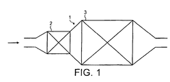
- a catalytic converter for a light-duty diesel vehicle is contained within an insulated metal housing, 1.
- the catalyst would conventionally be a "single-brick" or substrate.
- a catalyst first part, 2 is carried on a low thermal mass 400 cpsi (62.0 cells cm -2 ) metal support having a wall thickness of 0.05 mm.
- a catalyst second part, 3, is carried on a higher thermal mass 300 cpsi (46.5 cells cm -2 ) cordierite support having a wall thickness of 0.15 mm.
- Fig. 2 is a plot from computer modelling a two-part catalyst according to the present invention with varying heat capacities (0.5, 1 and 2 arbitrary units), over the ECE test cycle, when connected to a 2.5 litre TDI engine in a passenger vehicle.
- the importance of a relatively low heat capacity front or upstream catalyst can readily be seen.
- a relatively high heat capacity rear or downstream catalyst is much slower to heat up, but is more stable in later parts of the cycle.
- Figure 3 shows a bar chart of total tailpipe HC and CO in g/km for three averaged MVEG 'A' tests for European Stage III emissions compliance on a 1.9 litre TDI LDD passenger production vehicle certified to meet European stage III including three diesel oxidation catalyst arrangements, one according to the present invention.
- the black bar represents the results obtained for a relatively high thermal mass catalyst comprising a commercially available 6-inch (15.24 cm) long, 400 cpsi (62.0 cells cm -2 ) cordierite cylindrical flow-through substrate having a diameter at its faces of 4.66 inches (11.84 cm) and a cell wall thickness of 8 mm (volume 102 in 3 corresponding to a 1.7 litres).
- the total open frontal area was 70.6%.
- the white bar represents the results obtained for a relatively low thermal mass catalyst having the same dimensions to the relatively high thermal mass catalyst comprising a commercially available 400 cpsi (62.0 cells cm -2 ) cordierite flow-through substrate with 4 mm cell wall thickness and 84.6% open frontal area.
- the grey bar represents the results obtained for a catalyst arrangement according to the invention comprising an upstream first part including 2-inches (5 cm) of the relatively low thermal mass substrate described above and a 4-inch (10.16 cm) length of the relatively high thermal mass substrate mentioned above. In each case the substrate was coated with a gamma-alumina washcoat including a loading of 2.5g in -3 or 255g for the 1.7 litre total volume.
- each substrate was calcined and aged, also according to known methods.
- Each catalyst or catalyst combination was packaged in the same manner; insulated in a smgle can, and the can was inserted into a section of the exhaust system of the production passenger vehicle in exchange for the can/catalyst supplied with the vehicle.
Description
Claims (11)
- An oxidation catalyst (1) for a light-duty diesel vehicle comprising a first upstream part (2) and a second downstream part (3) of high heat capacity relative to the first part (2), each part comprising a substrate and a catalyst support coated thereon, characterised in that at least the substrate of the downstream catalyst part (3) is ceramic and the open cross-sectional area of the second part is greater than the open cross-sectional area of the first part, the arrangement being such that the exhaust gas has a longer residence time in the second part than in the first part.
- An oxidation catalyst according to claim 1, wherein the heat capacity of the downstream part (3) and is at least twice, preferably three and most preferably four times that of the upstream part (2).
- An oxidation catalyst according to claim 1 or 2, wherein the substrate wall thickness of the upstream catalyst part (2) is ≤ 0.10 mm, preferably ≤ 0.05 mm.
- An oxidation catalyst according to any preceding claim, wherein the substrate of the upstream catalyst part (2) is metal.
- An oxidation catalyst according to claim 3 or 4, wherein the upstream catalyst part (2) comprises a metal foil of ≤ 20µm thickness.
- An oxidation catalyst according to claim 3, 4 or 5, wherein the cell density of the upstream catalyst part substrate (2) is from 300 cells per square inch (cpsi) to 900 cpsi (46.5 - 139.5 cells cm-2), preferably from 300 to 600 cpsi (46.5 - 93.0 cells cm-2).
- An oxidation catalyst according to any preceding claim, wherein the substrate of the upstream catalyst part (2) is conical or frusto-conical in shape and is arranged with the smaller cross section upstream.
- An oxidation catalyst according to any preceding claim, wherein the substrate wall thickness of the downstream catalyst part (3) is ≥ 0.10 mm, preferably ≥ 0.15 mm.
- An oxidation catalyst according to any preceding claim, wherein the cell density of the downstream catalyst part substrate (3) is from 100 to 900 cpsi (15.5 - 139.5 cells cm-2), preferably from 200 to 600 cpsi (31.0 - 93.0 cells cm-2).
- A light-duty diesel vehicle including an exhaust system comprising an oxidation catalyst (1) according to any preceding claim.
- The use of an oxidation catalyst (1) according to any of claims 1 to 9 in a light-duty diesel vehicle to achieve rapid CO and/or HC light-off from cold-start relative to a conventional catalyst substrate and support combination and maintaining catalyst temperature substantially above the CO and/or HC light-off temperature after warm-up during urban driving.
Applications Claiming Priority (3)
| Application Number | Priority Date | Filing Date | Title |
|---|---|---|---|
| GBGB0003405.8A GB0003405D0 (en) | 2000-02-15 | 2000-02-15 | Improvements in emissions control |
| GB0003405 | 2000-02-15 | ||
| PCT/GB2001/000601 WO2001061163A1 (en) | 2000-02-15 | 2001-02-15 | Light-duty diesel catalysts |
Publications (2)
| Publication Number | Publication Date |
|---|---|
| EP1255918A1 EP1255918A1 (en) | 2002-11-13 |
| EP1255918B1 true EP1255918B1 (en) | 2005-07-06 |
Family
ID=9885592
Family Applications (1)
| Application Number | Title | Priority Date | Filing Date |
|---|---|---|---|
| EP01904189A Revoked EP1255918B1 (en) | 2000-02-15 | 2001-02-15 | Light-duty diesel catalysts |
Country Status (6)
| Country | Link |
|---|---|
| US (1) | US7141226B2 (en) |
| EP (1) | EP1255918B1 (en) |
| JP (1) | JP5362161B2 (en) |
| DE (1) | DE60111828T2 (en) |
| GB (2) | GB0003405D0 (en) |
| WO (1) | WO2001061163A1 (en) |
Cited By (3)
| Publication number | Priority date | Publication date | Assignee | Title |
|---|---|---|---|---|
| DE10130047B4 (en) * | 2001-06-21 | 2013-04-11 | Volkswagen Ag | Device for exhaust gas purification and its use |
| DE202009019007U1 (en) | 2008-05-07 | 2015-04-22 | Umicore Ag & Co. Kg | SCR catalyst for the reduction of nitrogen oxides in hydrocarbon-containing exhaust gases |
| DE102010063714C5 (en) | 2009-12-21 | 2018-03-29 | Johnson Matthey Public Limited Company | Exhaust system for a vehicle with a "stop-start" engine with compression ignition |
Families Citing this family (15)
| Publication number | Priority date | Publication date | Assignee | Title |
|---|---|---|---|---|
| US8833062B1 (en) | 2013-03-15 | 2014-09-16 | Daimier Ag | Catalytic reduction of NOx |
| GB0125729D0 (en) * | 2001-10-26 | 2001-12-19 | Johnson Matthey Plc | Catalyst substrate |
| US7862640B2 (en) | 2006-03-21 | 2011-01-04 | Donaldson Company, Inc. | Low temperature diesel particulate matter reduction system |
| JP4742942B2 (en) * | 2006-03-29 | 2011-08-10 | 三菱自動車工業株式会社 | Exhaust purification device |
| FR2906483B1 (en) * | 2006-09-29 | 2009-06-05 | Peugeot Citroen Automobiles Sa | MONOLITHIC SUPPORT FOR OXIDATION CATALYST ELEMENT, OXIDATION CATALYST ELEMENT COMPRISING IT, EXHAUST LINE EQUIPPED AND VEHICLE COMPRISING IT. |
| US20090199547A1 (en) * | 2008-02-08 | 2009-08-13 | Gm Global Technology Operations, Inc. | Method and apparatus for exhaust aftertreatment in a spark-ignition direct-injection internal combustion engine |
| EP2138681B1 (en) | 2008-06-27 | 2019-03-27 | Umicore AG & Co. KG | Method and device for cleaning diesel exhaust gases |
| US8033167B2 (en) * | 2009-02-24 | 2011-10-11 | Gary Miller | Systems and methods for providing a catalyst |
| US8920759B2 (en) * | 2009-03-02 | 2014-12-30 | GM Global Technology Operations LLC | Method and apparatus for reducing NOx emissions from a lean burning hydrocarbon fueled power source |
| JP2013169501A (en) * | 2012-02-20 | 2013-09-02 | Mitsubishi Motors Corp | Exhaust emission control device |
| US8850802B1 (en) | 2013-03-15 | 2014-10-07 | Daimler Ag | Catalytic reduction of NOx |
| JP6733651B2 (en) | 2017-12-27 | 2020-08-05 | トヨタ自動車株式会社 | Exhaust gas purification device for internal combustion engine |
| JP6733652B2 (en) * | 2017-12-27 | 2020-08-05 | トヨタ自動車株式会社 | Exhaust gas purification device for internal combustion engine |
| JP6729543B2 (en) | 2017-12-27 | 2020-07-22 | トヨタ自動車株式会社 | Exhaust gas purification device for internal combustion engine |
| CN113738483B (en) * | 2021-10-14 | 2023-12-01 | 无锡威孚力达催化净化器有限责任公司 | Control method and device for after-treatment system meeting ultralow emission |
Family Cites Families (16)
| Publication number | Priority date | Publication date | Assignee | Title |
|---|---|---|---|---|
| US3896616A (en) | 1972-04-21 | 1975-07-29 | Engelhard Min & Chem | Process and apparatus |
| JPS647935A (en) * | 1987-06-30 | 1989-01-11 | Nissan Motor | Catalytic converter device |
| US5108726A (en) * | 1988-08-19 | 1992-04-28 | Kerr-Mcgee Chemical Corporation | Compacts of spray dried water soluble compounds |
| JP2827532B2 (en) * | 1991-02-22 | 1998-11-25 | トヨタ自動車株式会社 | Catalyst device for reducing diesel particulates |
| RU2107828C1 (en) | 1992-04-03 | 1998-03-27 | Эмитек Гезелльшафт Фюр Эмиссионстехнологи Мбх | Honeycomb structure member |
| DE4226394C2 (en) | 1992-08-10 | 1999-01-21 | Degussa | Process for catalytic exhaust gas cleaning with improved cold start behavior |
| JPH08103664A (en) * | 1994-10-04 | 1996-04-23 | Nippondenso Co Ltd | Honeycomb body and catalytic converter having catalyst carrier consisting of the honeycomb body |
| US5599509A (en) * | 1993-03-17 | 1997-02-04 | Nippondenso Co., Ltd. | Honeycomb body and catalyst converter having catalyst carrier configured of this honeycomb |
| JP2904431B2 (en) * | 1993-03-26 | 1999-06-14 | 日本碍子株式会社 | Exhaust gas purification equipment |
| US5549873A (en) * | 1994-02-18 | 1996-08-27 | Volkswagen Ag | Exhaust gas converter arrangement |
| US6087298A (en) | 1996-05-14 | 2000-07-11 | Engelhard Corporation | Exhaust gas treatment system |
| GB2313796A (en) | 1996-06-08 | 1997-12-10 | Ford Motor Co | Catalytic converter for a lean burn engine |
| DE19820971A1 (en) | 1998-05-12 | 1999-11-18 | Emitec Emissionstechnologie | Catalytic converter for purifying the exhaust gas from an I.C. engine |
| JP3772583B2 (en) | 1998-06-01 | 2006-05-10 | 日産自動車株式会社 | Exhaust gas purification device for internal combustion engine |
| US6576203B2 (en) * | 1998-06-29 | 2003-06-10 | Ngk Insulators, Ltd. | Reformer |
| JP2000007304A (en) * | 1998-06-29 | 2000-01-11 | Ngk Insulators Ltd | Reforming reactor |
-
2000
- 2000-02-15 GB GBGB0003405.8A patent/GB0003405D0/en not_active Ceased
-
2001
- 2001-02-15 WO PCT/GB2001/000601 patent/WO2001061163A1/en active IP Right Grant
- 2001-02-15 DE DE60111828T patent/DE60111828T2/en not_active Expired - Lifetime
- 2001-02-15 US US10/204,020 patent/US7141226B2/en not_active Expired - Lifetime
- 2001-02-15 JP JP2001559989A patent/JP5362161B2/en not_active Expired - Fee Related
- 2001-02-15 EP EP01904189A patent/EP1255918B1/en not_active Revoked
- 2001-02-15 GB GB0103655A patent/GB2359264B/en not_active Expired - Fee Related
Cited By (8)
| Publication number | Priority date | Publication date | Assignee | Title |
|---|---|---|---|---|
| DE10130047B4 (en) * | 2001-06-21 | 2013-04-11 | Volkswagen Ag | Device for exhaust gas purification and its use |
| DE202009019007U1 (en) | 2008-05-07 | 2015-04-22 | Umicore Ag & Co. Kg | SCR catalyst for the reduction of nitrogen oxides in hydrocarbon-containing exhaust gases |
| DE202009019001U1 (en) | 2008-05-07 | 2015-05-11 | Umicore Ag & Co. Kg | Arrangement for the treatment of diesel engine exhaust gases containing nitrogen oxides (NOx) and hydrocarbons (HC) |
| EP2898941A1 (en) | 2008-05-07 | 2015-07-29 | Umicore AG & Co. KG | System for treating diesel engine exhaust gases containing nitrogen oxides and hydrocarbons |
| EP2918330A1 (en) | 2008-05-07 | 2015-09-16 | Umicore Ag & Co. Kg | Method for reducing nitrogen oxides in hydrocarbon containing waste gas streams using an scr catalytic converter on the basis of a molecular filter |
| EP2918329A1 (en) | 2008-05-07 | 2015-09-16 | Umicore Ag & Co. Kg | Method for reducing nitrogen oxides in hydrocarbon containing waste gas streams using an scr catalytic converter on the basis of a molecular filter |
| EP3195920A1 (en) | 2008-05-07 | 2017-07-26 | Umicore Ag & Co. Kg | Method for decreasing nitrogen oxides in hydrocarbon-containing exhaust gases using an scr catalyst based on a molecular sieve |
| DE102010063714C5 (en) | 2009-12-21 | 2018-03-29 | Johnson Matthey Public Limited Company | Exhaust system for a vehicle with a "stop-start" engine with compression ignition |
Also Published As
| Publication number | Publication date |
|---|---|
| JP2003522641A (en) | 2003-07-29 |
| GB2359264B (en) | 2004-02-25 |
| GB0003405D0 (en) | 2000-04-05 |
| US20030114300A1 (en) | 2003-06-19 |
| DE60111828T2 (en) | 2006-04-27 |
| WO2001061163A1 (en) | 2001-08-23 |
| EP1255918A1 (en) | 2002-11-13 |
| DE60111828D1 (en) | 2005-08-11 |
| GB2359264A (en) | 2001-08-22 |
| US7141226B2 (en) | 2006-11-28 |
| GB0103655D0 (en) | 2001-03-28 |
| JP5362161B2 (en) | 2013-12-11 |
Similar Documents
| Publication | Publication Date | Title |
|---|---|---|
| EP1255918B1 (en) | Light-duty diesel catalysts | |
| US6314722B1 (en) | Method and apparatus for emission control | |
| KR101838558B1 (en) | NOx TRAP | |
| EP0786284B1 (en) | A catalyst system | |
| KR101513120B1 (en) | Exhaust system comprising exotherm-generating catalyst | |
| US5939028A (en) | Combatting air pollution | |
| EP1313934B1 (en) | Exhaust system for lean-burn engines | |
| KR101978617B1 (en) | Exhaust system comprising a nox storage catalyst and catalysed soot filter | |
| US7293409B2 (en) | Process and system for improving combustion and exhaust aftertreatment of motor vehicle engines | |
| US10914217B2 (en) | Ammonia production catalyst and after treatment system | |
| JP3709953B2 (en) | Exhaust gas purification device for internal combustion engine | |
| EP3699408A1 (en) | Exhaust gas purification system for vehicle and method of controlling the same | |
| Keenan | Exhaust Emissions Control: 60 Years of Innovation and Development | |
| JP2022114539A (en) | Exhaust purification catalytic device and exhaust purification method using the device | |
| JP2600785B2 (en) | Exhaust gas purification device | |
| WO2003037507A1 (en) | Exhaust line for an internal combustion engine | |
| Hori et al. | Development of new selective NOx reduction catalyst for gasoline leanburn engines | |
| US8263009B2 (en) | Exhaust gas purifying catalyst | |
| US6568174B2 (en) | Process and apparatus for reducing warm-up emissions of a direct injection internal combustion engine | |
| Williamson et al. | Dual-Catalyst Underfloor LEV/ULEV Strategies for Effective Precious Metal Management | |
| EP1052010A1 (en) | Emission control system for internal combustion engine | |
| Johnson | SAE 2011 World Congress | |
| US20070009398A1 (en) | Waste gas cleaning system for an internal combustion engine | |
| JP3345927B2 (en) | How to clean diesel engine exhaust | |
| JP2004089881A (en) | Exhaust gas cleaning device |
Legal Events
| Date | Code | Title | Description |
|---|---|---|---|
| PUAI | Public reference made under article 153(3) epc to a published international application that has entered the european phase |
Free format text: ORIGINAL CODE: 0009012 |
|
| 17P | Request for examination filed |
Effective date: 20020729 |
|
| AK | Designated contracting states |
Kind code of ref document: A1 Designated state(s): AT BE CH CY DE DK ES FI FR GB GR IE IT LI LU MC NL PT SE TR |
|
| RBV | Designated contracting states (corrected) |
Designated state(s): AT BE CH CY DE DK FR GB IT LI SE |
|
| GRAP | Despatch of communication of intention to grant a patent |
Free format text: ORIGINAL CODE: EPIDOSNIGR1 |
|
| RBV | Designated contracting states (corrected) |
Designated state(s): BE DE FR GB IT SE |
|
| GRAS | Grant fee paid |
Free format text: ORIGINAL CODE: EPIDOSNIGR3 |
|
| GRAA | (expected) grant |
Free format text: ORIGINAL CODE: 0009210 |
|
| AK | Designated contracting states |
Kind code of ref document: B1 Designated state(s): BE DE FR GB IT SE |
|
| REG | Reference to a national code |
Ref country code: GB Ref legal event code: FG4D |
|
| REF | Corresponds to: |
Ref document number: 60111828 Country of ref document: DE Date of ref document: 20050811 Kind code of ref document: P |
|
| REG | Reference to a national code |
Ref country code: SE Ref legal event code: TRGR |
|
| ET | Fr: translation filed | ||
| PLBI | Opposition filed |
Free format text: ORIGINAL CODE: 0009260 |
|
| PLAX | Notice of opposition and request to file observation + time limit sent |
Free format text: ORIGINAL CODE: EPIDOSNOBS2 |
|
| 26 | Opposition filed |
Opponent name: UMICORE AG & CO. KG Effective date: 20060406 |
|
| PLAF | Information modified related to communication of a notice of opposition and request to file observations + time limit |
Free format text: ORIGINAL CODE: EPIDOSCOBS2 |
|
| PLBB | Reply of patent proprietor to notice(s) of opposition received |
Free format text: ORIGINAL CODE: EPIDOSNOBS3 |
|
| PGFP | Annual fee paid to national office [announced via postgrant information from national office to epo] |
Ref country code: GB Payment date: 20070115 Year of fee payment: 7 |
|
| PGFP | Annual fee paid to national office [announced via postgrant information from national office to epo] |
Ref country code: SE Payment date: 20070117 Year of fee payment: 7 |
|
| PGFP | Annual fee paid to national office [announced via postgrant information from national office to epo] |
Ref country code: DE Payment date: 20070118 Year of fee payment: 7 |
|
| PGFP | Annual fee paid to national office [announced via postgrant information from national office to epo] |
Ref country code: BE Payment date: 20070212 Year of fee payment: 7 |
|
| PLAY | Examination report in opposition despatched + time limit |
Free format text: ORIGINAL CODE: EPIDOSNORE2 |
|
| PGFP | Annual fee paid to national office [announced via postgrant information from national office to epo] |
Ref country code: IT Payment date: 20070525 Year of fee payment: 7 |
|
| PGFP | Annual fee paid to national office [announced via postgrant information from national office to epo] |
Ref country code: FR Payment date: 20070111 Year of fee payment: 7 |
|
| REG | Reference to a national code |
Ref country code: GB Ref legal event code: S29 |
|
| REG | Reference to a national code |
Ref country code: FR Ref legal event code: RT |
|
| PLAB | Opposition data, opponent's data or that of the opponent's representative modified |
Free format text: ORIGINAL CODE: 0009299OPPO |
|
| PG25 | Lapsed in a contracting state [announced via postgrant information from national office to epo] |
Ref country code: DE Free format text: LAPSE BECAUSE OF THE APPLICANT RENOUNCES Effective date: 20080416 |
|
| REG | Reference to a national code |
Ref country code: GB Ref legal event code: S29 |
|
| BERE | Be: lapsed |
Owner name: *JOHNSON MATTHEY P.L.C. Effective date: 20080228 |
|
| REG | Reference to a national code |
Ref country code: FR Ref legal event code: ST Effective date: 20081031 |
|
| RDAF | Communication despatched that patent is revoked |
Free format text: ORIGINAL CODE: EPIDOSNREV1 |
|
| PG25 | Lapsed in a contracting state [announced via postgrant information from national office to epo] |
Ref country code: GB Free format text: LAPSE BECAUSE OF THE APPLICANT RENOUNCES Effective date: 20080806 |
|
| PG25 | Lapsed in a contracting state [announced via postgrant information from national office to epo] |
Ref country code: BE Free format text: LAPSE BECAUSE OF NON-PAYMENT OF DUE FEES Effective date: 20080228 |
|
| RDAG | Patent revoked |
Free format text: ORIGINAL CODE: 0009271 |
|
| STAA | Information on the status of an ep patent application or granted ep patent |
Free format text: STATUS: PATENT REVOKED |
|
| PG25 | Lapsed in a contracting state [announced via postgrant information from national office to epo] |
Ref country code: FR Free format text: LAPSE BECAUSE OF NON-PAYMENT OF DUE FEES Effective date: 20080229 |
|
| 27W | Patent revoked |
Effective date: 20081229 |
|
| PG25 | Lapsed in a contracting state [announced via postgrant information from national office to epo] |
Ref country code: IT Free format text: LAPSE BECAUSE OF NON-PAYMENT OF DUE FEES Effective date: 20080215 |
|
| PG25 | Lapsed in a contracting state [announced via postgrant information from national office to epo] |
Ref country code: SE Free format text: LAPSE BECAUSE OF NON-PAYMENT OF DUE FEES Effective date: 20080216 |